EP0054504B1 - Système d'allumage piézo-électrique d'un brûleur à gaz avec sécurité, et appareils, notamment réfrigérateurs à absorption, pourvus d'un tel système - Google Patents
Système d'allumage piézo-électrique d'un brûleur à gaz avec sécurité, et appareils, notamment réfrigérateurs à absorption, pourvus d'un tel système Download PDFInfo
- Publication number
- EP0054504B1 EP0054504B1 EP19810420183 EP81420183A EP0054504B1 EP 0054504 B1 EP0054504 B1 EP 0054504B1 EP 19810420183 EP19810420183 EP 19810420183 EP 81420183 A EP81420183 A EP 81420183A EP 0054504 B1 EP0054504 B1 EP 0054504B1
- Authority
- EP
- European Patent Office
- Prior art keywords
- piezo
- push
- electric mechanism
- actuating means
- safety shutter
- Prior art date
- Legal status (The legal status is an assumption and is not a legal conclusion. Google has not performed a legal analysis and makes no representation as to the accuracy of the status listed.)
- Expired
Links
Images
Classifications
-
- F—MECHANICAL ENGINEERING; LIGHTING; HEATING; WEAPONS; BLASTING
- F23—COMBUSTION APPARATUS; COMBUSTION PROCESSES
- F23Q—IGNITION; EXTINGUISHING-DEVICES
- F23Q3/00—Igniters using electrically-produced sparks
- F23Q3/002—Igniters using electrically-produced sparks using piezoelectric elements
Definitions
- the present invention relates to a gas burner ignition system, combining on the one hand a temperature sensitive safety valve and on the other hand a piezoelectric mechanism.
- a gas burner ignition system combining on the one hand a temperature sensitive safety valve and on the other hand a piezoelectric mechanism.
- Such systems can be used on various gas appliances, such as water heaters, heating stoves, absorption refrigerators.
- thermo-sensitive safety valve in the sense of the present invention, it is necessary to understand a valve with inlet (connected to a gas source), and outlet (connected directly or indirectly to a burner), comprising within it a thermo element -sensitive (itself connected to a sensor arranged so as to be in contact with the burner flame), as well as an elastically charged pusher, making it possible to open the valve at least partially, in the absence of excitation of the thermosensitive element; when the burner is operating, it is the heat-sensitive element which keeps the valve open, the pusher then being released to return to its initial position, under the effect of its elastic load; when the burner stops working, the heat-sensitive element no longer acts, which leads to the automatic closing of the valve.
- the thermosensitive element and the sensor consist respectively of an electromagnet and a thermoelectric couple.
- piezoelectric mechanism within the meaning of the present invention, it is necessary to understand a compact system, with electrical outlet (connected to an electrode arranged so as to ignite by sparks the gaseous mixture leaving the burner, the rest of the mechanism being at the mass), comprising within it a piezoelectric ceramic, as well as an elastically charged thrust member making it possible, from the start or during its stroke, to generate by action on the piezoelectric ceramic a high electric voltage (which generates at least one spark between the electrode and the burner); when the thrust member is released, it returns to its initial position, under the effect of its elastic load.
- Such mechanisms can be single-spark (percussion) or multi-spark (compression).
- This solution leads to placing the safety valve and the piezoelectric mechanism in a fixed manner relative to each other, and to providing a relatively complex actuation means, both in its construction and in its operation to act successively. on the safety valve and on the piezoelectric mechanism.
- This complexity can in certain cases hamper the normal operation of the safety valve, for example by preventing the return of the pusher to its rest position, which is obviously not desirable in the event of the burner going out.
- the actuating means is integral with the pushing member of the piezoelectric mechanism, which by its part opposite to said pushing member cooperates with the pusher, the safety valve, and d on the other hand the force required to actuate the piezoelectric mechanism is greater than the force required to at least partially open the safety valve by means of the pusher.
- actuation means integral with the pushing member of the piezoelectric mechanism
- the actuation means push button for example
- the same means is distinct from the same member and connected to the latter, for example in rotation, the actuating means being capable of rotating relative to the thrust member of the piezoelectric mechanism.
- force necessary for actuating the piezoelectric mechanism is meant the value of the thrust from which the piezoelectric mechanism is actuated or triggered, and therefore at least one electric shock is produced.
- the thrust exerted on the thrust member increases with the displacement of the latter, in particular as a function of the deflection imposed on the elastic return load (spring in
- force necessary to at least partially open the safety valve is meant the value of the thrust exerted on the pusher, making it possible to at least partially open said valve, and ensuring the passage of a gas flow at least sufficient to ignition of the burner, with which said valve communicates.
- the thrust exerted on the pusher of the safety valve increases with the displacement of the latter, in particular as a function of the deflection imposed on the elastic return load (spring in general).
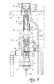
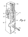
- a security system in accordance with the invention brings together, behind and against each other, an actuating means 1, a piezoelectric mechanism 2, and a safety valve 3.
- the safety valve is retained by two brackets 4 and 5, the vertical wing of which has an orifice adjusted to receive the body 6 of the safety valve.
- the safety valve is blocked on the support constituted by the two brackets 4 and 5 is effected on the one hand by the shouldered nut 7 bearing against the bracket 5, and on the other hand by a ring of stop 8 forcibly mounted on the other side of the same bracket.
- An intermediate piece 9 encloses the piezoelectric mechanism, and the pushing member 10 belonging to the latter freely exits from this piece.
- the actuating means, or push button 1 consists of two differently colored parts 11 and 12, fitted one on the other.
- the push button 1 is fixed to the pushing member 10 of the mechanism 2, by means of a screw 13 retaining the part 11 of the actuating means 1.
- the rear part of the intermediate part 9, opposite to the the pushing member 10 is fixed to the pusher 14 of the safety valve 3, for example by means of a clip 15, which is received in two slots provided on the part 9 and a circular groove provided on the pusher 14.
- An angle iron 16 having a flared orifice 17 serves as a guide for the push-button 1.
- the piezoelectric mechanism comprises a housing 18, the thrust member 10, movable in translation, being capable of sinking into the housing.
- a piezoelectric ceramic 19 is contained in the housing 18.
- the displacement of the thrust member 10 in the housing 18 makes it possible both to load a return spring 20, and to project in translation a striker 21 against the ceramic 19 , under the effect of another spring 22, previously loaded during the same movement of the thrust member 10; the percussion is triggered when the lug 23 integral with the striker 21 escapes from its housing 24 provided on the housing 18, under the effect of the ramp 25 provided on the thrust member 10.
- the return to the initial position of the thrust member 10 and striker 21 takes place under the sole effect of the return spring 20, the counter-ramp 26 provided on the member 10 bringing the lug 23 back into its housing 24.
- the safety valve 3 comprises the tubular body 6, the end opposite the nut 7 is associated with the pusher 14, loaded elastically towards the outside by a compression spring 27.
- the interior end of the pusher 14 has a rod 28 capable of acting on a valve 29 pushed against its seat 6a by means of another spring 30.
- a heat-sensitive element 31, for example an electromagnet, keeps the valve 29 open if the sensor (not shown) ) connected to it by a wire 32, reaches a determined temperature.
- the pusher 14 can be maintained in an intermediate position, thanks to the presence of balls 33 loaded centrifugally and cooperating with a chamfer 6b of the body.
- the safety valve is provided with a gas inlet 34 (about) located upstream of the valve 29, and a gas outlet 35 located downstream of the valve.
- the force necessary to open it at least partially by means of the pusher 14, that is to say the force necessary to move the valve 29 and reach between the latter and the seat a passage section sufficient to ignite the burner is approximately equal to the elastic load of the spring 27, plus the elastic load of the spring 30, when said sufficient passage section is reached. According to the invention, it is this force which must remain less than the actuation force of the piezoelectric mechanism.
- the invention applies to any gas burner appliance, in particular absorption refrigerators equipped with such a burner.
Landscapes
- Engineering & Computer Science (AREA)
- Chemical & Material Sciences (AREA)
- Combustion & Propulsion (AREA)
- Mechanical Engineering (AREA)
- General Engineering & Computer Science (AREA)
- Feeding And Controlling Fuel (AREA)
Applications Claiming Priority (2)
| Application Number | Priority Date | Filing Date | Title |
|---|---|---|---|
| FR8026988A FR2496233A1 (fr) | 1980-12-15 | 1980-12-15 | Systeme d'allumage piezo-electrique d'un bruleur a gaz avec securite, et appareils, notamment refrigerateurs a absorption, pourvus d'un tel systeme |
| FR8026988 | 1980-12-15 |
Publications (2)
| Publication Number | Publication Date |
|---|---|
| EP0054504A1 EP0054504A1 (fr) | 1982-06-23 |
| EP0054504B1 true EP0054504B1 (fr) | 1983-11-23 |
Family
ID=9249272
Family Applications (1)
| Application Number | Title | Priority Date | Filing Date |
|---|---|---|---|
| EP19810420183 Expired EP0054504B1 (fr) | 1980-12-15 | 1981-12-11 | Système d'allumage piézo-électrique d'un brûleur à gaz avec sécurité, et appareils, notamment réfrigérateurs à absorption, pourvus d'un tel système |
Country Status (4)
| Country | Link |
|---|---|
| EP (1) | EP0054504B1 (ref) |
| DE (1) | DE3161515D1 (ref) |
| FR (1) | FR2496233A1 (ref) |
| HU (1) | HU183737B (ref) |
Families Citing this family (1)
| Publication number | Priority date | Publication date | Assignee | Title |
|---|---|---|---|---|
| CN105674549B (zh) * | 2016-04-01 | 2019-03-05 | 邓辉 | 一种全自动压电电子打火热水器 |
Family Cites Families (4)
| Publication number | Priority date | Publication date | Assignee | Title |
|---|---|---|---|---|
| NL6716173A (ref) * | 1967-11-28 | 1969-05-30 | ||
| FR2099023A5 (ref) * | 1970-10-27 | 1972-03-10 | Leblanc Marcel | |
| FR2112637A5 (ref) * | 1970-11-03 | 1972-06-23 | Antargaz | |
| ES179600Y (es) * | 1972-04-22 | 1973-12-01 | Metalicas De Pamplona, S. A. | Dispositivo accionador aplicable al encendido de estufas degas. |
-
1980
- 1980-12-15 FR FR8026988A patent/FR2496233A1/fr active Granted
-
1981
- 1981-12-11 DE DE8181420183T patent/DE3161515D1/de not_active Expired
- 1981-12-11 EP EP19810420183 patent/EP0054504B1/fr not_active Expired
- 1981-12-14 HU HU376181A patent/HU183737B/hu not_active IP Right Cessation
Also Published As
| Publication number | Publication date |
|---|---|
| FR2496233B1 (ref) | 1983-02-18 |
| EP0054504A1 (fr) | 1982-06-23 |
| HU183737B (en) | 1984-05-28 |
| FR2496233A1 (fr) | 1982-06-18 |
| DE3161515D1 (en) | 1983-12-29 |
Similar Documents
| Publication | Publication Date | Title |
|---|---|---|
| FR2843327A1 (fr) | Outil de scellement actionne par combustion interne | |
| EP0054504B1 (fr) | Système d'allumage piézo-électrique d'un brûleur à gaz avec sécurité, et appareils, notamment réfrigérateurs à absorption, pourvus d'un tel système | |
| FR2604510A1 (fr) | Cuisiniere a gaz comportant un bruleur de cuisson situe au-dessous d'une plaque de vitrocerame | |
| EP0333540B1 (fr) | Robinet pour gaz équipé d'un système de sécurité à thermocouple, et appareil utilisant un tel robinet | |
| US2912841A (en) | Pyrophoric igniting device | |
| CH419899A (fr) | Dispositif de détente pour arme à feu | |
| EP1597534A1 (fr) | Fusee de projectile | |
| US3617160A (en) | Device for actuating the friction wheel of a pyrophoric lighter | |
| JPS589075Y2 (ja) | ガス器具用安全元弁 | |
| FR2667125A1 (fr) | Bouton de commande combine pour appareil a gaz. | |
| CH275000A (fr) | Dispositif de commande pour brûleur à gaz. | |
| FR1464789A (fr) | Dispositif d'allumage automatique pour brûleur à gaz | |
| WO1982003117A1 (fr) | Systeme de commande de l'alimentation en energie d'un appareil a gaz et a electricite | |
| EP0165082A1 (fr) | Mécanisme d'armement à rigidité variable pour appareils de production instantannée d'eau chaude par le gaz | |
| US578004A (en) | Alfred czarnikow | |
| FR2561757A1 (fr) | Chauffe-bains a gaz sans veilleuse permanente | |
| CH266453A (fr) | Dispositif de réglage de débit et d'obturation pour briquets et allumeurs à gaz. | |
| EP0269509A1 (fr) | Robinet d'admission gaz à sécurité intégrée pour appareil de production d'eau chaude sans veilleuse permanente | |
| CH368112A (fr) | Dispositif de commande d'un brûleur à gaz | |
| FR2489938A1 (fr) | Dispositif de purge rapide du mecanisme de commande pour appareils a gaz | |
| FR2642828A1 (fr) | Dispositif de securite a la percussion en cas de chute d'appareil actionne par l'explosion d'une cartouche | |
| FR2607907A1 (fr) | Chauffe-eau | |
| GB1308031A (en) | Ignition safety devices for gas fired appliances | |
| JPH0552543U (ja) | プッシュ式器具栓 | |
| FR2730794A1 (fr) | Mecanisme gaz pour chauffe-bains a gaz sans veilleuse permanente a commande electronique |
Legal Events
| Date | Code | Title | Description |
|---|---|---|---|
| PUAI | Public reference made under article 153(3) epc to a published international application that has entered the european phase |
Free format text: ORIGINAL CODE: 0009012 |
|
| AK | Designated contracting states |
Designated state(s): BE CH DE FR GB IT LI LU NL SE |
|
| 17P | Request for examination filed |
Effective date: 19820630 |
|
| ITF | It: translation for a ep patent filed | ||
| GRAA | (expected) grant |
Free format text: ORIGINAL CODE: 0009210 |
|
| AK | Designated contracting states |
Designated state(s): BE CH DE FR GB IT LI LU NL SE |
|
| PGFP | Annual fee paid to national office [announced via postgrant information from national office to epo] |
Ref country code: LU Payment date: 19831123 Year of fee payment: 3 |
|
| REF | Corresponds to: |
Ref document number: 3161515 Country of ref document: DE Date of ref document: 19831229 |
|
| PG25 | Lapsed in a contracting state [announced via postgrant information from national office to epo] |
Ref country code: LU Free format text: LAPSE BECAUSE OF NON-PAYMENT OF DUE FEES Effective date: 19831231 |
|
| PLBE | No opposition filed within time limit |
Free format text: ORIGINAL CODE: 0009261 |
|
| PGFP | Annual fee paid to national office [announced via postgrant information from national office to epo] |
Ref country code: FR Payment date: 19841116 Year of fee payment: 4 |
|
| 26N | No opposition filed | ||
| PGFP | Annual fee paid to national office [announced via postgrant information from national office to epo] |
Ref country code: CH Payment date: 19841214 Year of fee payment: 4 |
|
| PGFP | Annual fee paid to national office [announced via postgrant information from national office to epo] |
Ref country code: SE Payment date: 19841231 Year of fee payment: 4 Ref country code: BE Payment date: 19841231 Year of fee payment: 4 |
|
| PGFP | Annual fee paid to national office [announced via postgrant information from national office to epo] |
Ref country code: DE Payment date: 19850226 Year of fee payment: 4 |
|
| PGFP | Annual fee paid to national office [announced via postgrant information from national office to epo] |
Ref country code: NL Payment date: 19851231 Year of fee payment: 5 |
|
| PG25 | Lapsed in a contracting state [announced via postgrant information from national office to epo] |
Ref country code: SE Effective date: 19861212 |
|
| PG25 | Lapsed in a contracting state [announced via postgrant information from national office to epo] |
Ref country code: LI Effective date: 19861231 Ref country code: CH Effective date: 19861231 Ref country code: BE Effective date: 19861231 |
|
| BERE | Be: lapsed |
Owner name: APPLICATION DES GAZ Effective date: 19861231 |
|
| PG25 | Lapsed in a contracting state [announced via postgrant information from national office to epo] |
Ref country code: NL Effective date: 19870701 |
|
| NLV4 | Nl: lapsed or anulled due to non-payment of the annual fee | ||
| GBPC | Gb: european patent ceased through non-payment of renewal fee | ||
| PG25 | Lapsed in a contracting state [announced via postgrant information from national office to epo] |
Ref country code: FR Free format text: LAPSE BECAUSE OF NON-PAYMENT OF DUE FEES Effective date: 19870831 |
|
| REG | Reference to a national code |
Ref country code: CH Ref legal event code: PL |
|
| PG25 | Lapsed in a contracting state [announced via postgrant information from national office to epo] |
Ref country code: DE Effective date: 19870901 |
|
| REG | Reference to a national code |
Ref country code: FR Ref legal event code: ST |
|
| PG25 | Lapsed in a contracting state [announced via postgrant information from national office to epo] |
Ref country code: GB Free format text: LAPSE BECAUSE OF NON-PAYMENT OF DUE FEES Effective date: 19881118 |
|
| EUG | Se: european patent has lapsed |
Ref document number: 81420183.6 Effective date: 19870917 |