EP0054477B1 - Antriebseinrichtung mit Zylindern zur Erzeugung der kontinuierlichen Bewegung eines länglichen Gegenstandes in Richtung seiner Achse und/oder zum Bewegen eines Elementes längs diesem Gegenstand - Google Patents
Antriebseinrichtung mit Zylindern zur Erzeugung der kontinuierlichen Bewegung eines länglichen Gegenstandes in Richtung seiner Achse und/oder zum Bewegen eines Elementes längs diesem Gegenstand Download PDFInfo
- Publication number
- EP0054477B1 EP0054477B1 EP81401947A EP81401947A EP0054477B1 EP 0054477 B1 EP0054477 B1 EP 0054477B1 EP 81401947 A EP81401947 A EP 81401947A EP 81401947 A EP81401947 A EP 81401947A EP 0054477 B1 EP0054477 B1 EP 0054477B1
- Authority
- EP
- European Patent Office
- Prior art keywords
- piston
- jack
- pistons
- article
- movement
- Prior art date
- Legal status (The legal status is an assumption and is not a legal conclusion. Google has not performed a legal analysis and makes no representation as to the accuracy of the status listed.)
- Expired
Links
Images

Classifications
-
- E—FIXED CONSTRUCTIONS
- E02—HYDRAULIC ENGINEERING; FOUNDATIONS; SOIL SHIFTING
- E02B—HYDRAULIC ENGINEERING
- E02B17/00—Artificial islands mounted on piles or like supports, e.g. platforms on raisable legs or offshore constructions; Construction methods therefor
- E02B17/04—Equipment specially adapted for raising, lowering, or immobilising the working platform relative to the supporting construction
- E02B17/08—Equipment specially adapted for raising, lowering, or immobilising the working platform relative to the supporting construction for raising or lowering
- E02B17/0836—Equipment specially adapted for raising, lowering, or immobilising the working platform relative to the supporting construction for raising or lowering with climbing jacks
-
- B—PERFORMING OPERATIONS; TRANSPORTING
- B66—HOISTING; LIFTING; HAULING
- B66F—HOISTING, LIFTING, HAULING OR PUSHING, NOT OTHERWISE PROVIDED FOR, e.g. DEVICES WHICH APPLY A LIFTING OR PUSHING FORCE DIRECTLY TO THE SURFACE OF A LOAD
- B66F1/00—Devices, e.g. jacks, for lifting loads in predetermined steps
- B66F1/02—Devices, e.g. jacks, for lifting loads in predetermined steps with locking elements, e.g. washers, co-operating with posts
- B66F1/04—Devices, e.g. jacks, for lifting loads in predetermined steps with locking elements, e.g. washers, co-operating with posts the posts being toothed
- B66F1/08—Devices, e.g. jacks, for lifting loads in predetermined steps with locking elements, e.g. washers, co-operating with posts the posts being toothed and the devices being operated by fluid pressure
Definitions
- the present invention relates to a power plant with jacks for producing the continuous movement of an oblong object in the direction of its axis, in particular when this axis is vertical, and / or for moving an element along said object.
- elong object is meant to designate any kind of elongated object, such as bar, rod, tube, cable, etc., of uniform or non-uniform cross section, it being understood that by “axis is meant the general direction in which extends said object, and not necessarily an axis in the geometric sense of the term, that is to say an axis of revolution or symmetry.
- the object in question can constitute any mobile mechanical member, for example a hoisting member, the installation in question then being fixed.
- it can be fixed (post), in which case the installation in question is mobile along this object and can in turn entail, for example to hoist it, any element.
- installations of the general type comprising on the one hand at least two sets of jacks, the piston or pistons of each set being associated with locking means specific to them. selectively, momentarily and automatically secure said object, their body being fixed (in the case of a movable oblong object) or mobile and secured to an element to be moved along said object (in the case of a fixed oblong object), and on the other hand, a device for supplying the bodies of the cylinders with hydraulic fluid, provided with automatic control means (pumps; solenoid valves; position detectors; amplifiers; etc.) for supplying or evacuating the fluid on either side of said pistons, the arrangement and operation of the aforementioned locking and control means being ensured in such a way, at least, that the taking up of said object by the piston or pistons of a cylinder assemblies are performed at the time that the piston or pistons of the other set of cylinders cease their own taking over of said object, the piston
- Document FR-A-2169 048 describes an installation comprising a transport trolley for very heavy loads, using a main hydraulic cylinder and a hydraulic fixing cylinder, and it would not be adapted to the problem either. , which is in particular that of the continuous displacement of an oblong object in the direction of its axis, in particular when this axis is vertical.
- the document FR-A-1 525 052 describes a hydraulic device for hauling a cable, again using two jacks working alternately, one performing a traction movement, while the other returns empty in its starting position, but again such a device is not suitable for moving a load in an essentially vertical direction.
- the object of the present invention is to fill this gap in the technique and, for this purpose, a power plant with cylinders in accordance with the invention is characterized in that said empty displacement of the piston or pistons takes place at higher speed. that their displacement under load, to allow a catching up of the games at the level of the locking means, in order to avoid suddenly.
- Another object of the invention consists in the production of a hydraulic circuit, as described in claim 8, for the supply of this power plant.
- the invention may include other provisions, in particular to allow a rocking movement perfectly synchronized between said pistons of the cylinder assemblies, and to allow easy blocking on the object, and in particular the installation above defined under its the most general form can also be characterized, for this purpose, in that the arrangement and operation of said locking and control means are also ensured so that from a stop position at the end of stroke under load, and after release, the start of the empty return of the piston (s) of an actuator assembly to their starting position, namely the start of their empty movement in the opposite direction to the direction of relative displacement of the object with respect to this assembly, is automatically controlled in an instant which follows the start of the taking over of said object by the piston or pistons of the other cylinder assembly.
- period of time which elapses between this start of treatment and the instant in question may correspond approximately to the time necessary to ensure release at the end of the race under load. This will also be better seen later.
- any embodiment adapted to the problem posed and in particular that it comprises two sets of cylinders each comprising a annular piston surrounding said oblong object, the two pistons being mounted in a common cylinder body also annular and surrounding said object.
- This arrangement advantageously makes it possible to obtain a compact and robust installation, and also allows a simplification, the chambers of the two sets of jacks being able to communicate directly inside the common jack body.
- One can also facilitate, in this way, the mechanical connection (by bolts or the like) between the pistons and the oblong object.
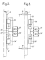
- the installation comprises two sets of cylinders each comprising an annular piston surrounding said oblong object, the two pistons being mounted in two separate cylinder bodies, also annular, coaxial and surrounding said object. .
- FIG. 1 there is referenced at 1, in the form of a tube, the oblong object which it is desired to subject to a continuous displacement in the direction of its axis 2.
- the cylinder assembly comprises in this example two jacks having a common body 3 mounted, on a fixed support 4, so as to surround said tube 1.
- the body 3 consists of two cylindrical and concentric walls 3a and 3b connected at both ends by bottoms 3c and thus defining in the body 3 a common annular chamber 5.
- the diameter of the inner tubular wall 3a is slightly greater than that of the tube 1.
- annular chamber 5 In the annular chamber 5 are slidably mounted two annular pistons 6 and 6 'each extended by a tubular part, respectively 7 and 7', leaving the common body 3 by the two ends of the latter and each of which carries means for the end blocking, respectively 8 and 8 '.
- These means can be constituted by any means adapted to temporarily block the corresponding tubular part 7 or 7 'on the tube 1; it may, for example, be locking means comprising pins or the like, respectively 9 and 9 ′, adapted to move radially towards the axis 2 or in the opposite direction, either to be able to engage in a light or the like 10 of the tube is to be able to disengage from it, it being understood that the lights 10 can be distributed at constant spacings both according to the length of the tube and along its periphery.
- the circuit for supplying the chamber 5 with hydraulic fluid has been shown very schematically. It comprises in particular pipes 17 and 17 ′ opening at both ends of the chamber, crossing the bottoms 3c, and a pipe 18 opening into the central part of the chamber crossing the cylindrical wall 3b, these various pipes being able to be placed in communication with pumps 19 and 19 'via valves, respectively 20 to 23 and 20' to 23 ', these valves being connected according to the arrangement indicated in the sin.
- the position, in the direction of the axis 2, of the pistons 6, 6 'in the chamber 5 can be determined by means of position detectors (not shown) and which make it possible to determine the instants at which these pistons arrive, for the piston 6 at the levels indicated by the lines N1, N2, N3 and N4, and for the piston 6 'at the levels indicated by the lines N'1. N'2, N'3 and N'4.
- control links between the level detectors and the locking means 8, 8 ′ on the one hand, and the various valves 20 to 23 on the other, have not been shown. and 20 'to 23'.
- the explanations which will follow on the operation of the installation which has just been described will easily make it possible to see how these operational links between the various organs of the installation must be carried out.
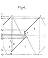
- FIG. 4 time is shown on the abscissa and the position of the pistons 6, 6 ′ along the ordinate in the direction of the axis 2.
- the parts in reinforced line of the two diagrams represented in this figure designate the displacements of the pistons in load, that is to say when by means of pins 9 or 9 'they exert a thrust (which will be assumed directed upwards in FIG. 1) on the tube or other oblong object 1.
- valves 21 ′ and 23 ′ are automatically closed, which causes the piston 6 ′ to descend.
- FIG. 4 the operational interconnections between the controls of the pistons 6 and 6 ′ have been shown diagrammatically in the form of dashed vertical lines I, II and III.
- Line I clearly shows that the taking over of the tube 1 by the piston 6 'immediately follows the end of the taking over of this tube by the other piston 6, as well as the taking over of the tube by the piston 6 immediately follows the end of the support of this tube by the piston 6 '.
- Line II shows that when a piston comes under load at level N2 or N'2, it automatically controls the start of the rise of the other piston and its locking in relation to tube 1.
- line III shows that when a piston arrives under load at level N3 or N'3, it automatically controls the start of the descent with no load from the other piston.
- the object 1 may in particular be an object to be hoisted, or on the contrary an object to be lowered, for example to sink it into the ground, to effect sinking, drilling or the like.
- This object 1 instead of being mobile, as in the example which has just been described, could also be constituted by a fixed post, and in this case of course, it is the common cylinder body 3 which would move, likewise in a perfectly continuous manner, along the object 1, by driving any element, for example an element to be hoisted at the top of the post or the like.
- the object 1 can be of the same type as according to Figure 1, there are provided two separate cylinder bodies 24 and 24', annular, surrounding the oblong object 1 and in each of which is mounted a piston also annular, respectively 25 and 25 '.
- the means for supplying the two separate cylinder bodies with hydraulic fluid can be of the same type as those which have been previously described and they have been globally referenced at 26 for the body 24 and 26 'for the body 24'.
- Operation may in any case be similar to that which has been described with reference to FIG. 1.
Landscapes
- Engineering & Computer Science (AREA)
- General Engineering & Computer Science (AREA)
- Mechanical Engineering (AREA)
- Structural Engineering (AREA)
- Civil Engineering (AREA)
- Physics & Mathematics (AREA)
- Fluid Mechanics (AREA)
- Life Sciences & Earth Sciences (AREA)
- Geology (AREA)
- Actuator (AREA)
- Drilling And Boring (AREA)
- Electrical Discharge Machining, Electrochemical Machining, And Combined Machining (AREA)
- Excavating Of Shafts Or Tunnels (AREA)
- Specific Conveyance Elements (AREA)
- Variable-Direction Aerials And Aerial Arrays (AREA)
- Linear Motors (AREA)
- Ultra Sonic Daignosis Equipment (AREA)
- Seasonings (AREA)
- Medicines That Contain Protein Lipid Enzymes And Other Medicines (AREA)
- Earth Drilling (AREA)
Claims (8)
Priority Applications (1)
| Application Number | Priority Date | Filing Date | Title |
|---|---|---|---|
| AT81401947T ATE21504T1 (de) | 1980-12-16 | 1981-12-07 | Antriebseinrichtung mit zylindern zur erzeugung der kontinuierlichen bewegung eines laenglichen gegenstandes in richtung seiner achse und/oder zum bewegen eines elementes laengs diesem gegenstand. |
Applications Claiming Priority (2)
| Application Number | Priority Date | Filing Date | Title |
|---|---|---|---|
| FR8026697A FR2496074B1 (fr) | 1980-12-16 | 1980-12-16 | Installation motrice a verins pour produire le deplacement continu d'un objet oblong dans la direction de son axe, et/ou pour mouvoir un element le long dudit objet |
| FR8026697 | 1980-12-16 |
Publications (2)
| Publication Number | Publication Date |
|---|---|
| EP0054477A1 EP0054477A1 (de) | 1982-06-23 |
| EP0054477B1 true EP0054477B1 (de) | 1986-08-20 |
Family
ID=9249155
Family Applications (1)
| Application Number | Title | Priority Date | Filing Date |
|---|---|---|---|
| EP81401947A Expired EP0054477B1 (de) | 1980-12-16 | 1981-12-07 | Antriebseinrichtung mit Zylindern zur Erzeugung der kontinuierlichen Bewegung eines länglichen Gegenstandes in Richtung seiner Achse und/oder zum Bewegen eines Elementes längs diesem Gegenstand |
Country Status (10)
| Country | Link |
|---|---|
| US (1) | US4535971A (de) |
| EP (1) | EP0054477B1 (de) |
| JP (1) | JPS57121600A (de) |
| AT (1) | ATE21504T1 (de) |
| CA (1) | CA1171401A (de) |
| DE (1) | DE3175177D1 (de) |
| ES (1) | ES8300302A1 (de) |
| FI (1) | FI814019A7 (de) |
| FR (1) | FR2496074B1 (de) |
| NO (1) | NO814275L (de) |
Cited By (1)
| Publication number | Priority date | Publication date | Assignee | Title |
|---|---|---|---|---|
| CN111908361A (zh) * | 2020-08-25 | 2020-11-10 | 广东电网有限责任公司 | 一种机械式小型千斤顶 |
Families Citing this family (7)
| Publication number | Priority date | Publication date | Assignee | Title |
|---|---|---|---|---|
| SU1404693A1 (ru) * | 1984-04-24 | 1988-06-23 | Управление "Спецшахтомонтаж" Производственного Объединения По Добыче Угля "Карагандауголь" | Гидравлический шаговый привод |
| DD271619A3 (de) * | 1987-04-03 | 1989-09-13 | Bauakademie Ddr | Einrichtung zum kontinuierlichen bewegen von lasten |
| FR2615422A1 (fr) * | 1987-05-22 | 1988-11-25 | Bielecki Stanislas | Dispositif pour mise en tension de cables de precontrainte, de haubans, d'amarres, ou pour deplacement de charges lourdes |
| DE8816758U1 (de) * | 1988-02-11 | 1990-06-21 | Techno Mark AG, Rotkreuz | Druckmittelbetriebene Stell- oder Arbeitsvorrichtung |
| RU2339567C1 (ru) * | 2007-02-15 | 2008-11-27 | Государственное образовательное учреждение высшего профессионального образования "Южно-Российский государственный технический университет (Новочеркасский политехнический институт)" | Привод подъемного устройства |
| CN105804037A (zh) * | 2016-04-08 | 2016-07-27 | 上海尚鉴机械工程有限公司 | 海洋平台自动升降控制方法 |
| US11286965B2 (en) | 2016-05-19 | 2022-03-29 | Saab Ab | Fluid actuator arrangement and a method for control of a fluid actuator arrangement |
Family Cites Families (15)
| Publication number | Priority date | Publication date | Assignee | Title |
|---|---|---|---|---|
| US2961837A (en) * | 1956-09-28 | 1960-11-29 | Delong Corp | Supporting leg assembly for marine platform |
| US3135345A (en) * | 1961-02-06 | 1964-06-02 | Arthur W Scruggs | Multi-ped vehicle |
| CH440617A (de) * | 1965-04-28 | 1967-07-31 | Werkzeugfabrik Selzach Ag | Antriebsausrüstung |
| FR1525052A (fr) * | 1966-11-16 | 1968-05-17 | Tractel Sa | Tire-câble hydraulique à mouvement continu uniforme |
| US3537684A (en) * | 1968-05-23 | 1970-11-03 | Joe Stine Inc | Pipe handling apparatus |
| GB1309232A (en) * | 1969-03-14 | 1973-03-07 | Press W & Son Ltd | Rope pulling apparatus |
| NL7107756A (de) * | 1970-06-09 | 1971-12-13 | ||
| SE354635B (de) * | 1972-01-12 | 1973-03-19 | N Ahlgren | |
| BE794549A (fr) * | 1972-01-27 | 1973-05-16 | Mitsui Shipbuilding Eng | Chariot pour le transport de poids lourds |
| DE2502984A1 (de) * | 1974-01-30 | 1975-07-31 | Ahlgren Nils H | Schwerlast-hebezeug |
| FR2266657B1 (de) * | 1974-04-08 | 1977-09-30 | Charbonnages De France | |
| SE394191B (sv) * | 1975-10-07 | 1977-06-13 | Anderson Ind Ab Paul | Sett vid lagring av for overforing av stora krafter avsedda anordningar samt anordning for settets genomforande |
| GB1579484A (en) * | 1977-03-15 | 1980-11-19 | Coal Industry Patents Ltd | Engagement devices |
| US4286771A (en) * | 1977-09-13 | 1981-09-01 | Coal Industry (Patents) Limited | Haulage apparatus for mining machines |
| FR2424451A1 (fr) * | 1978-04-28 | 1979-11-23 | Delattre Levivier | Dispositif d'entrainement d'un mobile |
-
1980
- 1980-12-16 FR FR8026697A patent/FR2496074B1/fr not_active Expired
-
1981
- 1981-12-07 DE DE8181401947T patent/DE3175177D1/de not_active Expired
- 1981-12-07 AT AT81401947T patent/ATE21504T1/de not_active IP Right Cessation
- 1981-12-07 EP EP81401947A patent/EP0054477B1/de not_active Expired
- 1981-12-09 CA CA000391836A patent/CA1171401A/en not_active Expired
- 1981-12-11 ES ES507895A patent/ES8300302A1/es not_active Expired
- 1981-12-15 FI FI814019A patent/FI814019A7/fi not_active Application Discontinuation
- 1981-12-15 NO NO814275A patent/NO814275L/no unknown
- 1981-12-15 JP JP56202361A patent/JPS57121600A/ja active Pending
-
1983
- 1983-12-08 US US06/559,017 patent/US4535971A/en not_active Expired - Fee Related
Cited By (1)
| Publication number | Priority date | Publication date | Assignee | Title |
|---|---|---|---|---|
| CN111908361A (zh) * | 2020-08-25 | 2020-11-10 | 广东电网有限责任公司 | 一种机械式小型千斤顶 |
Also Published As
| Publication number | Publication date |
|---|---|
| ATE21504T1 (de) | 1986-09-15 |
| ES507895A0 (es) | 1982-11-01 |
| FR2496074A1 (fr) | 1982-06-18 |
| FI814019L (fi) | 1982-06-17 |
| DE3175177D1 (en) | 1986-09-25 |
| US4535971A (en) | 1985-08-20 |
| FR2496074B1 (fr) | 1985-08-16 |
| JPS57121600A (en) | 1982-07-29 |
| CA1171401A (en) | 1984-07-24 |
| FI814019A7 (fi) | 1982-06-17 |
| EP0054477A1 (de) | 1982-06-23 |
| NO814275L (no) | 1982-06-17 |
| ES8300302A1 (es) | 1982-11-01 |
Similar Documents
| Publication | Publication Date | Title |
|---|---|---|
| EP1525371B1 (de) | Teleskopführungsleitung für offshore-bohren | |
| EP1148207B1 (de) | Verbindungsvorrichtung für eine Unterwasser-Flüssigkeitstransportleitung | |
| FR2565289A1 (fr) | Appareil de forage de puits avec unite de commande au sommet et elevateur retenu contre rotation | |
| EP0054477B1 (de) | Antriebseinrichtung mit Zylindern zur Erzeugung der kontinuierlichen Bewegung eines länglichen Gegenstandes in Richtung seiner Achse und/oder zum Bewegen eines Elementes längs diesem Gegenstand | |
| FR2584449A1 (fr) | Ensemble superieur pour tube prolongateur marin, joint coulissant auto-tensionneur, joint de palier de rotation, conduit tubulaire, navire et procede les utilisant | |
| CA2075076A1 (fr) | Systeme, support pour effectuer des mesures ou interventions dans un puits fore ou en cours de forage, et leurs utilisations | |
| FR2779754A1 (fr) | Dispositif de transport et de pose d'un pont d'une plate-forme petroliere d'exploitation en mer | |
| WO1996000359A1 (fr) | Dispositif de pose de conduites flexibles a partir d'un support flottant | |
| FR2567211A1 (fr) | Couplage mecanique reversible pour ancrage sous tension | |
| EP0382607A1 (de) | Vorrichtung zum Herstellen von Pfählen im Boden mit einem kontinuierlichen hohlen Bohrer | |
| EP0244542A1 (de) | Verfahren und Vorrichtung zum Heben, insbesondere für eine Ölproduktionsplattform | |
| EP0225815A1 (de) | Werkzeug zum Absperren eines Produktionssteigrohres | |
| CA1301637C (fr) | Systeme d'accrochage et de tensionement a distance d'un element allonge | |
| EP0112752A1 (de) | Einrichtung zum Klemmen und Rundformen für das Anschliessen von Rohren grossen Durchmessers | |
| FR2517764A1 (fr) | Connecteurs pour relier ensemble des elements avec une grande force de serrage, notamment les elements tubulaires d'une installation de forage | |
| FR2886372A1 (fr) | Dispositif destine a realiser l'alimentation en huile d'un outil monte sur un engin porteur et ensemble de connexion hydraulique | |
| EP0677437A1 (de) | Verfahren und Vorrichtung gegen die Längsbewegung von Wasserfahrzeugen | |
| FR2670477A1 (fr) | Grue, en particulier pour la manutention. | |
| EP1438478A1 (de) | Führungsvorrichtung in einer offshore-bohranlage | |
| EP0210092B1 (de) | Schrittweise arbeitende Antriebsvorrichtung | |
| FR2522081A1 (fr) | Verin moufle a double effet utilisable notamment pour commander les mouvements de fermeture et d'ouverture d'une porte coulissante ou basculante | |
| FR3029219A1 (fr) | Dispositif de barriere a element de fermeture escamotable | |
| FR2512878A1 (fr) | Verin de puits supporte sur une structure de montage de table rotative | |
| FR2477258A1 (fr) | Dispositif de liaison entre une structure flottante ou semi-flottante ou semi-immergee et une conduite de remontee a partir du fond sous-marin | |
| FR2590881A1 (fr) | Dispositif de manutention motorise |
Legal Events
| Date | Code | Title | Description |
|---|---|---|---|
| PUAI | Public reference made under article 153(3) epc to a published international application that has entered the european phase |
Free format text: ORIGINAL CODE: 0009012 |
|
| AK | Designated contracting states |
Designated state(s): AT BE CH DE GB IT LU NL SE |
|
| 17P | Request for examination filed |
Effective date: 19821213 |
|
| ITF | It: translation for a ep patent filed | ||
| GRAA | (expected) grant |
Free format text: ORIGINAL CODE: 0009210 |
|
| AK | Designated contracting states |
Kind code of ref document: B1 Designated state(s): AT BE CH DE GB IT LI LU NL SE |
|
| REF | Corresponds to: |
Ref document number: 21504 Country of ref document: AT Date of ref document: 19860915 Kind code of ref document: T |
|
| REF | Corresponds to: |
Ref document number: 3175177 Country of ref document: DE Date of ref document: 19860925 |
|
| PGFP | Annual fee paid to national office [announced via postgrant information from national office to epo] |
Ref country code: AT Payment date: 19861120 Year of fee payment: 6 |
|
| PG25 | Lapsed in a contracting state [announced via postgrant information from national office to epo] |
Ref country code: LU Free format text: LAPSE BECAUSE OF NON-PAYMENT OF DUE FEES Effective date: 19861231 |
|
| PGFP | Annual fee paid to national office [announced via postgrant information from national office to epo] |
Ref country code: NL Payment date: 19861231 Year of fee payment: 6 |
|
| PLBE | No opposition filed within time limit |
Free format text: ORIGINAL CODE: 0009261 |
|
| STAA | Information on the status of an ep patent application or granted ep patent |
Free format text: STATUS: NO OPPOSITION FILED WITHIN TIME LIMIT |
|
| 26N | No opposition filed | ||
| PG25 | Lapsed in a contracting state [announced via postgrant information from national office to epo] |
Ref country code: AT Effective date: 19871207 |
|
| PG25 | Lapsed in a contracting state [announced via postgrant information from national office to epo] |
Ref country code: SE Effective date: 19871208 |
|
| PG25 | Lapsed in a contracting state [announced via postgrant information from national office to epo] |
Ref country code: LI Effective date: 19871231 Ref country code: CH Effective date: 19871231 Ref country code: BE Effective date: 19871231 |
|
| BERE | Be: lapsed |
Owner name: CIE FRANCAISE D'ENTREPRISES METALLIQUES Effective date: 19871231 |
|
| PG25 | Lapsed in a contracting state [announced via postgrant information from national office to epo] |
Ref country code: NL Effective date: 19880701 |
|
| NLV4 | Nl: lapsed or anulled due to non-payment of the annual fee | ||
| GBPC | Gb: european patent ceased through non-payment of renewal fee | ||
| REG | Reference to a national code |
Ref country code: CH Ref legal event code: PL |
|
| PG25 | Lapsed in a contracting state [announced via postgrant information from national office to epo] |
Ref country code: DE Effective date: 19880901 |
|
| PG25 | Lapsed in a contracting state [announced via postgrant information from national office to epo] |
Ref country code: GB Free format text: LAPSE BECAUSE OF NON-PAYMENT OF DUE FEES Effective date: 19881118 |
|
| EUG | Se: european patent has lapsed |
Ref document number: 81401947.7 Effective date: 19880913 |