EP0054477B1 - Motorized installation with jacks for producing the continuous movement of an oblong object in the direction of its axis and/or for moving an element along this object - Google Patents
Motorized installation with jacks for producing the continuous movement of an oblong object in the direction of its axis and/or for moving an element along this object Download PDFInfo
- Publication number
- EP0054477B1 EP0054477B1 EP81401947A EP81401947A EP0054477B1 EP 0054477 B1 EP0054477 B1 EP 0054477B1 EP 81401947 A EP81401947 A EP 81401947A EP 81401947 A EP81401947 A EP 81401947A EP 0054477 B1 EP0054477 B1 EP 0054477B1
- Authority
- EP
- European Patent Office
- Prior art keywords
- piston
- jack
- pistons
- article
- movement
- Prior art date
- Legal status (The legal status is an assumption and is not a legal conclusion. Google has not performed a legal analysis and makes no representation as to the accuracy of the status listed.)
- Expired
Links
Images

Classifications
-
- E—FIXED CONSTRUCTIONS
- E02—HYDRAULIC ENGINEERING; FOUNDATIONS; SOIL SHIFTING
- E02B—HYDRAULIC ENGINEERING
- E02B17/00—Artificial islands mounted on piles or like supports, e.g. platforms on raisable legs or offshore constructions; Construction methods therefor
- E02B17/04—Equipment specially adapted for raising, lowering, or immobilising the working platform relative to the supporting construction
- E02B17/08—Equipment specially adapted for raising, lowering, or immobilising the working platform relative to the supporting construction for raising or lowering
- E02B17/0836—Equipment specially adapted for raising, lowering, or immobilising the working platform relative to the supporting construction for raising or lowering with climbing jacks
-
- B—PERFORMING OPERATIONS; TRANSPORTING
- B66—HOISTING; LIFTING; HAULING
- B66F—HOISTING, LIFTING, HAULING OR PUSHING, NOT OTHERWISE PROVIDED FOR, e.g. DEVICES WHICH APPLY A LIFTING OR PUSHING FORCE DIRECTLY TO THE SURFACE OF A LOAD
- B66F1/00—Devices, e.g. jacks, for lifting loads in predetermined steps
- B66F1/02—Devices, e.g. jacks, for lifting loads in predetermined steps with locking elements, e.g. washers, co-operating with posts
- B66F1/04—Devices, e.g. jacks, for lifting loads in predetermined steps with locking elements, e.g. washers, co-operating with posts the posts being toothed
- B66F1/08—Devices, e.g. jacks, for lifting loads in predetermined steps with locking elements, e.g. washers, co-operating with posts the posts being toothed and the devices being operated by fluid pressure
Definitions
- the present invention relates to a power plant with jacks for producing the continuous movement of an oblong object in the direction of its axis, in particular when this axis is vertical, and / or for moving an element along said object.
- elong object is meant to designate any kind of elongated object, such as bar, rod, tube, cable, etc., of uniform or non-uniform cross section, it being understood that by “axis is meant the general direction in which extends said object, and not necessarily an axis in the geometric sense of the term, that is to say an axis of revolution or symmetry.
- the object in question can constitute any mobile mechanical member, for example a hoisting member, the installation in question then being fixed.
- it can be fixed (post), in which case the installation in question is mobile along this object and can in turn entail, for example to hoist it, any element.
- installations of the general type comprising on the one hand at least two sets of jacks, the piston or pistons of each set being associated with locking means specific to them. selectively, momentarily and automatically secure said object, their body being fixed (in the case of a movable oblong object) or mobile and secured to an element to be moved along said object (in the case of a fixed oblong object), and on the other hand, a device for supplying the bodies of the cylinders with hydraulic fluid, provided with automatic control means (pumps; solenoid valves; position detectors; amplifiers; etc.) for supplying or evacuating the fluid on either side of said pistons, the arrangement and operation of the aforementioned locking and control means being ensured in such a way, at least, that the taking up of said object by the piston or pistons of a cylinder assemblies are performed at the time that the piston or pistons of the other set of cylinders cease their own taking over of said object, the piston
- Document FR-A-2169 048 describes an installation comprising a transport trolley for very heavy loads, using a main hydraulic cylinder and a hydraulic fixing cylinder, and it would not be adapted to the problem either. , which is in particular that of the continuous displacement of an oblong object in the direction of its axis, in particular when this axis is vertical.
- the document FR-A-1 525 052 describes a hydraulic device for hauling a cable, again using two jacks working alternately, one performing a traction movement, while the other returns empty in its starting position, but again such a device is not suitable for moving a load in an essentially vertical direction.
- the object of the present invention is to fill this gap in the technique and, for this purpose, a power plant with cylinders in accordance with the invention is characterized in that said empty displacement of the piston or pistons takes place at higher speed. that their displacement under load, to allow a catching up of the games at the level of the locking means, in order to avoid suddenly.
- Another object of the invention consists in the production of a hydraulic circuit, as described in claim 8, for the supply of this power plant.
- the invention may include other provisions, in particular to allow a rocking movement perfectly synchronized between said pistons of the cylinder assemblies, and to allow easy blocking on the object, and in particular the installation above defined under its the most general form can also be characterized, for this purpose, in that the arrangement and operation of said locking and control means are also ensured so that from a stop position at the end of stroke under load, and after release, the start of the empty return of the piston (s) of an actuator assembly to their starting position, namely the start of their empty movement in the opposite direction to the direction of relative displacement of the object with respect to this assembly, is automatically controlled in an instant which follows the start of the taking over of said object by the piston or pistons of the other cylinder assembly.
- period of time which elapses between this start of treatment and the instant in question may correspond approximately to the time necessary to ensure release at the end of the race under load. This will also be better seen later.
- any embodiment adapted to the problem posed and in particular that it comprises two sets of cylinders each comprising a annular piston surrounding said oblong object, the two pistons being mounted in a common cylinder body also annular and surrounding said object.
- This arrangement advantageously makes it possible to obtain a compact and robust installation, and also allows a simplification, the chambers of the two sets of jacks being able to communicate directly inside the common jack body.
- One can also facilitate, in this way, the mechanical connection (by bolts or the like) between the pistons and the oblong object.
- the installation comprises two sets of cylinders each comprising an annular piston surrounding said oblong object, the two pistons being mounted in two separate cylinder bodies, also annular, coaxial and surrounding said object. .
- FIG. 1 there is referenced at 1, in the form of a tube, the oblong object which it is desired to subject to a continuous displacement in the direction of its axis 2.
- the cylinder assembly comprises in this example two jacks having a common body 3 mounted, on a fixed support 4, so as to surround said tube 1.
- the body 3 consists of two cylindrical and concentric walls 3a and 3b connected at both ends by bottoms 3c and thus defining in the body 3 a common annular chamber 5.
- the diameter of the inner tubular wall 3a is slightly greater than that of the tube 1.
- annular chamber 5 In the annular chamber 5 are slidably mounted two annular pistons 6 and 6 'each extended by a tubular part, respectively 7 and 7', leaving the common body 3 by the two ends of the latter and each of which carries means for the end blocking, respectively 8 and 8 '.
- These means can be constituted by any means adapted to temporarily block the corresponding tubular part 7 or 7 'on the tube 1; it may, for example, be locking means comprising pins or the like, respectively 9 and 9 ′, adapted to move radially towards the axis 2 or in the opposite direction, either to be able to engage in a light or the like 10 of the tube is to be able to disengage from it, it being understood that the lights 10 can be distributed at constant spacings both according to the length of the tube and along its periphery.
- the circuit for supplying the chamber 5 with hydraulic fluid has been shown very schematically. It comprises in particular pipes 17 and 17 ′ opening at both ends of the chamber, crossing the bottoms 3c, and a pipe 18 opening into the central part of the chamber crossing the cylindrical wall 3b, these various pipes being able to be placed in communication with pumps 19 and 19 'via valves, respectively 20 to 23 and 20' to 23 ', these valves being connected according to the arrangement indicated in the sin.
- the position, in the direction of the axis 2, of the pistons 6, 6 'in the chamber 5 can be determined by means of position detectors (not shown) and which make it possible to determine the instants at which these pistons arrive, for the piston 6 at the levels indicated by the lines N1, N2, N3 and N4, and for the piston 6 'at the levels indicated by the lines N'1. N'2, N'3 and N'4.
- control links between the level detectors and the locking means 8, 8 ′ on the one hand, and the various valves 20 to 23 on the other, have not been shown. and 20 'to 23'.
- the explanations which will follow on the operation of the installation which has just been described will easily make it possible to see how these operational links between the various organs of the installation must be carried out.
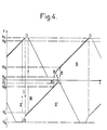
- FIG. 4 time is shown on the abscissa and the position of the pistons 6, 6 ′ along the ordinate in the direction of the axis 2.
- the parts in reinforced line of the two diagrams represented in this figure designate the displacements of the pistons in load, that is to say when by means of pins 9 or 9 'they exert a thrust (which will be assumed directed upwards in FIG. 1) on the tube or other oblong object 1.
- valves 21 ′ and 23 ′ are automatically closed, which causes the piston 6 ′ to descend.
- FIG. 4 the operational interconnections between the controls of the pistons 6 and 6 ′ have been shown diagrammatically in the form of dashed vertical lines I, II and III.
- Line I clearly shows that the taking over of the tube 1 by the piston 6 'immediately follows the end of the taking over of this tube by the other piston 6, as well as the taking over of the tube by the piston 6 immediately follows the end of the support of this tube by the piston 6 '.
- Line II shows that when a piston comes under load at level N2 or N'2, it automatically controls the start of the rise of the other piston and its locking in relation to tube 1.
- line III shows that when a piston arrives under load at level N3 or N'3, it automatically controls the start of the descent with no load from the other piston.
- the object 1 may in particular be an object to be hoisted, or on the contrary an object to be lowered, for example to sink it into the ground, to effect sinking, drilling or the like.
- This object 1 instead of being mobile, as in the example which has just been described, could also be constituted by a fixed post, and in this case of course, it is the common cylinder body 3 which would move, likewise in a perfectly continuous manner, along the object 1, by driving any element, for example an element to be hoisted at the top of the post or the like.
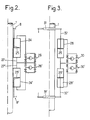
- the object 1 can be of the same type as according to Figure 1, there are provided two separate cylinder bodies 24 and 24', annular, surrounding the oblong object 1 and in each of which is mounted a piston also annular, respectively 25 and 25 '.
- the means for supplying the two separate cylinder bodies with hydraulic fluid can be of the same type as those which have been previously described and they have been globally referenced at 26 for the body 24 and 26 'for the body 24'.
- Operation may in any case be similar to that which has been described with reference to FIG. 1.
Abstract
Description
La présente invention concerne une installation motrice à vérins pour produire le déplacement continu d'un objet oblong dans la direction de son axe, en particulier lorsque cet axe est vertical, et/ou pour mouvoir un élément le long dudit objet.The present invention relates to a power plant with jacks for producing the continuous movement of an oblong object in the direction of its axis, in particular when this axis is vertical, and / or for moving an element along said object.
Par « objet oblong », on entend désigner toute espèce d'objet allongé, tel que barre, tige, tube, câble, etc, de section uniforme ou non, étant entendu que par « axe on désigne la direction générale selon laquelle s'étend ledit objet, et non pas forcément un axe au sens géométrique du terme, c'est-à-dire un axe de révolution ou de symétrie.By "oblong object" is meant to designate any kind of elongated object, such as bar, rod, tube, cable, etc., of uniform or non-uniform cross section, it being understood that by "axis is meant the general direction in which extends said object, and not necessarily an axis in the geometric sense of the term, that is to say an axis of revolution or symmetry.
L'objet en question peut constituer tout organe mécanique mobile, par exemple un organe de hissage, l'installation en question étant alors fixe. Il peut au contraire être fixe (poteau), auquel cas l'installation en question est mobile le long de cet objet et peut à son tour entraîner, par exemple pour le hisser, un élément quelconque.The object in question can constitute any mobile mechanical member, for example a hoisting member, the installation in question then being fixed. On the contrary, it can be fixed (post), in which case the installation in question is mobile along this object and can in turn entail, for example to hoist it, any element.
On connaît déjà des installations motrices pour produire le déplacement d'un objet oblong, ou d'un élément le long d'un tel objet, notamment à vérins, mais on n'en connaît pas, jusqu'à présent, qui soit apte à produire un déplacement parfaitement continu de l'objet ou de l'élément, sans à- coups, et sans temps d'arrêt.Motor installations are already known for producing the displacement of an oblong object, or of an element along such an object, in particular with jacks, but no one has so far been known which is capable of produce a perfectly continuous movement of the object or element, without jerks, and without downtime.
On connaît ainsi, par exemple par le document GB-A-1 309 232 des installations du type général comportant d'une part au moins deux ensembles à vérins, le ou les pistons de chaque ensemble étant associés à des moyens de blocage propres à les solidariser sélectivement, momentanément et automatiquement dudit objet, leur corps étant fixe (dans le cas d'un objet oblong mobile) ou mobile et solidarisé d'un élément à mouvoir le long dudit objet (dans le cas d'un objet oblong fixe), et d'autre part un dispositif d'alimentation des corps de vérins en fluide hydraulique, pourvu de moyens automatiques de commande (pompes ; électro-vannes ; détecteurs de position ; amplificateurs ; etc.) de l'amenée ou de l'évacuation du fluide d'un côté et d'autre desdits pistons, l'agencement et le fonctionnement des moyens précités de blocage et de commande étant assurés de telle manière, au moins, que la prise en charge dudit objet par le ou les pistons d'un des ensembles à vérins s'effectue à l'instant auquel le ou les pistons de l'autre ensemble à vérins cessent leur propre prise en charge dudit objet, le ou les pistons d'un ensemble ayant par rapport à ceux de l'autre ensemble, et en synchronisme, un mouvement général de bascule.There are thus known, for example from document GB-A-1 309 232, installations of the general type comprising on the one hand at least two sets of jacks, the piston or pistons of each set being associated with locking means specific to them. selectively, momentarily and automatically secure said object, their body being fixed (in the case of a movable oblong object) or mobile and secured to an element to be moved along said object (in the case of a fixed oblong object), and on the other hand, a device for supplying the bodies of the cylinders with hydraulic fluid, provided with automatic control means (pumps; solenoid valves; position detectors; amplifiers; etc.) for supplying or evacuating the fluid on either side of said pistons, the arrangement and operation of the aforementioned locking and control means being ensured in such a way, at least, that the taking up of said object by the piston or pistons of a cylinder assemblies are performed at the time that the piston or pistons of the other set of cylinders cease their own taking over of said object, the piston or pistons of one set having with respect to those of the other set, and in synchronism, a general rocking movement.
Toutefois, il s'agit ici d'une installation mettant en oeuvre des pinces auto-serrables pour solidariser momentanément les pistons des ensembles à vérins de l'objet à déplacer, lequel est constitué d'un câble ou analogue, déplacé horizontalement.However, this is an installation using self-tightening pliers for temporarily securing the pistons of the cylinder assemblies of the object to be moved, which consists of a cable or the like, moved horizontally.
Une telle installation ne serait pas appropriée à un déplacement vertical d'un objet pesant lorsqu'elle comporte à cet effet, en tant que moyens de verrouillage, des systèmes à broches, celles-ci étant destinées à s'engager dans des ouvertures correspondantes de l'objet, car alors se pose le problème de la compensation des jeux, lesquels sont inévitables entre lesdites broches et les ouvertures coopérantes de l'objet.Such an installation would not be suitable for a vertical movement of a heavy object when it comprises for this purpose, as locking means, pin systems, these being intended to engage in corresponding openings of the object, because then there is the problem of compensating for the clearances, which are inevitable between said pins and the cooperating openings of the object.
Le document FR-A-2169 048 décrit quant à lui une installation comportant un chariot transporteur pour très lourdes charges, faisant appel à un vérin hydraulique principal et à un vérin hydraulique de fixation, et elle ne serait elle non plus pas adaptée au problème posé, qui est notamment celui du déplacement continu d'un objet oblong dans la direction de son axe, en particulier lorsque cet axe est vertical.Document FR-A-2169 048 describes an installation comprising a transport trolley for very heavy loads, using a main hydraulic cylinder and a hydraulic fixing cylinder, and it would not be adapted to the problem either. , which is in particular that of the continuous displacement of an oblong object in the direction of its axis, in particular when this axis is vertical.
Le document FR-A-1 525 052 décrit quant à lui un dispositif hydraulique de halage d'un câble utilisant là encore deux vérins travaillant en alternance, l'un effectuant un mouvement de traction, tandis que l'autre revient à vide dans sa position de départ, mais là encore un tel dispositif n'est pas adapté au déplacement d'une charge dans une direction essentiellement verticale.The document FR-A-1 525 052 describes a hydraulic device for hauling a cable, again using two jacks working alternately, one performing a traction movement, while the other returns empty in its starting position, but again such a device is not suitable for moving a load in an essentially vertical direction.
Le but de la présente invention est de combler cette lacune de la technique et, à cet effet, une installation motrice à vérins conforme à l'invention est caractérisée en ce que ledit déplacement à vide du ou des pistons s'effectue à plus grande vitesse que leur déplacement sous charge, pour permettre un rattrapage des jeux au niveau des moyens de blocage, afin d'éviter tout-à-coup.The object of the present invention is to fill this gap in the technique and, for this purpose, a power plant with cylinders in accordance with the invention is characterized in that said empty displacement of the piston or pistons takes place at higher speed. that their displacement under load, to allow a catching up of the games at the level of the locking means, in order to avoid suddenly.
Un autre but de l'invention consiste dans la réalisation d'un circuit hydraulique, tel que décrit dans la revendication 8, pour l'alimentation de cette installation motrice.Another object of the invention consists in the production of a hydraulic circuit, as described in
L'invention peut comporter d'autres dispositions, notamment pour permettre un mouvement de bascule parfaitement synchronisé entre lesdits pistons des ensembles à vérins, et pour permettre un blocage aisé sur l'objet, et en particulier l'installation ci-dessus définie sous sa forme la plus générale pourra encore être caractérisée, à cet effet, en ce que l'agencement et le fonctionnement desdits moyens de blocage et de commande sont en outre assurés de telle manière qu'à partir d'une position d'arrêt en fin de course sous charge, et après déblocage, le début du retour à vide du ou des pistons d'un ensemble à verins vers leur position de départ, à savoir le début de leur déplacement à vide dans le sens opposé au sens du déplacement relatif de l'objet par rapport à cet ensemble, est commandé automatiquement en un instant qui suit le début de la prise en charge dudit objet par le ou les pistons de l'autre ensemble à vérins.The invention may include other provisions, in particular to allow a rocking movement perfectly synchronized between said pistons of the cylinder assemblies, and to allow easy blocking on the object, and in particular the installation above defined under its the most general form can also be characterized, for this purpose, in that the arrangement and operation of said locking and control means are also ensured so that from a stop position at the end of stroke under load, and after release, the start of the empty return of the piston (s) of an actuator assembly to their starting position, namely the start of their empty movement in the opposite direction to the direction of relative displacement of the object with respect to this assembly, is automatically controlled in an instant which follows the start of the taking over of said object by the piston or pistons of the other cylinder assembly.
On comprend que le laps de temps qui s'écoule entre ce début de prise en charge et l'instant en question pourra correspondre approximativement au temps nécessaire pour assurer le déblocage en fin de course sous charge. Ceci également sera mieux vu par la suite.It is understood that the period of time which elapses between this start of treatment and the instant in question may correspond approximately to the time necessary to ensure release at the end of the race under load. This will also be better seen later.
Sur le plan de la réalisation pratique, on peut prévoir, pour les ensembles à vérins d'une installation conforme à l'invention, tout mode d'exécution adapté au problème posé, et notamment qu'elle comporte deux ensembles à vérins comportant chacun un piston annulaire entourant ledit objet oblong, les deux pistons étant montés dans un corps de vérin commun également annulaire et entourant ledit objet.In terms of practical implementation, one can provide, for the cylinder assemblies of an installation according to the invention, any embodiment adapted to the problem posed, and in particular that it comprises two sets of cylinders each comprising a annular piston surrounding said oblong object, the two pistons being mounted in a common cylinder body also annular and surrounding said object.
Cette disposition permet avantageusement d'obtenir une installation compacte et robuste, et permet aussi une simplification, les chambres des deux ensembles à vérins pouvant communiquer directement à l'intérieur du corps de vérin commun. On peut faciliter aussi, de cette manière, la liaison mécanique (par verrous ou analogues) entre les pistons et l'objet oblong.This arrangement advantageously makes it possible to obtain a compact and robust installation, and also allows a simplification, the chambers of the two sets of jacks being able to communicate directly inside the common jack body. One can also facilitate, in this way, the mechanical connection (by bolts or the like) between the pistons and the oblong object.
On peut toutefois prévoir d'autres agencements, et notamment que l'installation comporte deux ensembles à vérins comportant chacun un piston annulaire entourant ledit objet oblong, les deux pistons étant montés dans deux corps de vérins séparés, également annulaires, coaxiaux et entourant ledit objet.However, other arrangements can be made, and in particular that the installation comprises two sets of cylinders each comprising an annular piston surrounding said oblong object, the two pistons being mounted in two separate cylinder bodies, also annular, coaxial and surrounding said object. .
On peut prévoir encore, dans certains cas d'application, des couples de vérins classiques ou des monovérins à double piston montés autour dudit objet oblong selon un agencement permettant un équilibrage des efforts sur les pistons et une action globale ou résultante dirigée selon l'axe dudit objet.It is also possible, in certain application cases, to couple conventional cylinders or double piston single cylinders mounted around said oblong object in an arrangement allowing a balancing of the forces on the pistons and a global or resulting action directed along the axis. said object.
Quel que soit le mode d'exécution choisi, on pourra mettre en oeuvre, par ailleurs, pour l'actionnement des moyens précités de blocage et de commande, tous moyens appropriés de détection, de régulation et autres, courants dans le genre de technique en question, et prévoir notamment que le ou les corps de vérins sont associés à des détecteurs de la position du piston dans le corps correspondant, ces détecteurs étant en liaison, par l'intermédiaire d'amplificateurs ou analogues, d'une part avec les électro-vannes ou analogues, aptes à commander l'amenée ou l'évacuation de fluide hydraulique dans ou hors les corps de vérins, d'un côté ou de l'autre du piston dont la position est détectée et/ou du piston d'autres vérins, et d'autre part avec lesdits moyens de blocage, pour assurer la solidarisation ou la désolidarisation momentanées entre pistons et objet oblong.Whatever the mode of execution chosen, it will be possible to use, moreover, for the actuation of the aforementioned blocking and control means, all appropriate means of detection, regulation and the like, common in the kind of technique in question, and provide in particular that the cylinder body or bodies are associated with detectors of the position of the piston in the corresponding body, these detectors being connected, by means of amplifiers or the like, on the one hand to the electro -valves or the like, capable of controlling the supply or evacuation of hydraulic fluid into or out of the cylinders bodies, on one side or the other of the piston whose position is detected and / or of the piston of other cylinders, and on the other hand with said blocking means, to ensure the momentary securing or detachment between pistons and oblong object.
Des modes d'exécution de l'invention vont maintenant être décrits à titre d'exemples nullement limitatifs, avec référence aux figures du dessin annexé dans lequel :
- la figure 1 représente schématiquement une installation conforme à l'invention, du type comprenant un corps de vérin annulaire commun à deux ensembles à vérins, ce corps étant représenté en demi-coupe et demi-vue extérieure ;
- la figure 2 représente de même schématiquement une autre installation conforme à l'invention, du type comprenant deux ensembles à vérins à piston annulaire, les pistons annulaires étant ici montés dans des corps de vérins séparés ;
- la figure 3 représente schématiquement encore une autre installation conforme à l'invention, du type comprenant deux ensembles à vérins, à couples de vérins classiques ; et
- la figure 4 est un exemple d'un des diagrammes possibles, représentant, en fonction du temps, les déplacements des pistons desdits ensembles à vérins.
- Figure 1 schematically shows an installation according to the invention, of the type comprising an annular cylinder body common to two sets of cylinders, this body being shown in half-section and half external view;
- FIG. 2 likewise schematically represents another installation in accordance with the invention, of the type comprising two sets of cylinders with an annular piston, the annular pistons being here mounted in separate cylinder bodies;
- FIG. 3 schematically represents yet another installation according to the invention, of the type comprising two sets of jacks, with pairs of conventional jacks; and
- Figure 4 is an example of one of the possible diagrams, representing, as a function of time, the movements of the pistons of said cylinder assemblies.
A la figure 1, on a référencé en 1, sous la forme d'un tube, l'objet oblong que l'on désire soumettre à un déplacement continu dans la direction de son axe 2. L'ensemble à vérins comporte dans cet exemple deux vérins ayant un corps commun 3 monté, sur un appui fixe 4, de sorte à entourer ledit tube 1. Le corps 3 est constitué de deux parois cylindriques et concentriques 3a et 3b reliées aux deux extrémités par des fonds 3c et définissant ainsi dans le corps 3 une chambre annulaire commune 5. Le diamètre de la paroi tubulaire intérieure 3a est légèrement supérieur à celui du tube 1.In Figure 1, there is referenced at 1, in the form of a tube, the oblong object which it is desired to subject to a continuous displacement in the direction of its
Dans la chambre annulaire 5 sont montés coulissants deux pistons annulaires 6 et 6' prolongés chacun par une partie tubulaire, respectivement 7 et 7', sortant du corps commun 3 par les deux extrémités de celui-ci et dont chacune porte en bout des moyens de blocage, respectivement 8 et 8'. Ces moyens peuvent être constitués par tous moyens adaptés à effectuer un blocage momentané de la partie tubulaire correspondante 7 ou 7' sur le tube 1 ; il peut s'agir par exemple de moyens de verrouillage comprenant des broches ou analogues, respectivement 9 et 9', propres à se mouvoir radialement vers l'axe 2 ou dans la direction opposée, soit pour pouvoir s'engager dans une lumière ou analogue 10 du tube soit pour pouvoir s'en dégager, étant entendu que les lumières 10 peuvent être réparties à espacements constants tant selon la longueur du tube que selon sa périphérie.In the
Pour ce qui est de l'étanchéité entre les pistons 6, 6' et leur partie tubulaire respective 7, 7' d'une part et le corps commun de vérin 3 d'autre part, elle peut être assurée là encore par tous moyens appropriés et par exemple, comme indiqué sur le dessin, par des joints annulaires, respectivement 11 à 14 et 11' à 14'.As regards the seal between the
On a également représenté sur le dessin, en 15, une entretoise reliant les deux parois cylindriques 3a et 3b mais laissant en communication les parties supérieure et inférieure de la chambre 5, et, en 16, 16', des voiles ou analogues de renforcement des pistons 6, 6'.Also shown in the drawing, in 15, a spacer connecting the two
Sur la figure 1, le circuit d'alimentation de la chambre 5 en fluide hydraulique a été représenté très schématiquement. Il comporte notamment des conduites 17 et 17' débouchant aux deux extrémités de la chambre, en traversant les fonds 3c, et une conduite 18 débouchant dans la partie centrale de la chambre en traversant la paroi cylindrique 3b, ces différentes conduites pouvant être mises en communication avec des pompes 19 et 19' par l'intermédiaire de vannes, respectivement 20 à 23 et 20' à 23', ces vannes étant branchées selon la disposition indiquée au dessin.In FIG. 1, the circuit for supplying the
La position, selon la direction de l'axe 2, des pistons 6, 6' dans la chambre 5 peut être déterminée grâce à des détecteurs de position (non représentés) et qui permettent de déterminer les instants auxquels ces pistons arrivent, pour le piston 6 aux niveaux indiqués par les traits N1, N2, N3 et N4, et pour le piston 6' aux niveaux indiqués par les traits N'1. N'2, N'3 et N'4.The position, in the direction of the
Pour ne pas alourdir le dessin, on n'a pas représenté non plus les liaisons de commande entre les détecteurs de niveau, et d'une part les moyens de blocage 8, 8', et d'autre part les différentes vannes 20 à 23 et 20' à 23'. Les explications qui vont suivre sur le fonctionnement de l'installation qui vient d'être décrite permettront facilement de voir comment ces liaisons opératives entre les différents organes de l'installation doivent être effectuées.In order not to burden the drawing, the control links between the level detectors and the locking means 8, 8 ′ on the one hand, and the
Ceci étant, on se reportera pour cette explication du fonctionnement de l'installation aux figures 1 et 4.That said, for this explanation of the operation of the installation, reference is made to FIGS. 1 and 4.
Sur la figure 4, on a représenté en abscisses le temps et en ordonnées la position des pistons 6, 6' selon la direction de l'axe 2. Les parties en trait renforcé des deux diagrammes représentés sur cette figure désignent les déplacements des pistons en charge, c'est-à-dire lorsque par l'intermédiaire des broches 9 ou 9' ils exercent une poussée (que l'on supposera dirigée vers le haut de la figure 1) sur le tube ou autre objet oblong 1.In FIG. 4, time is shown on the abscissa and the position of the
On a supposé qu'au temps t = 0, le piston 6 monte en charge tandis que le piston 6' descend (sur la figure 4, on a indiqué pour les montées en charge des pentes inférieures, en valeur absolue, aux pentes de descente sans charge). A cet instant, les vannes 21, 23, 20' et 22' sont ouvertes, tandis que les vannes 20, 22, 21' et 23' sont fermées.It has been assumed that at time t = 0, the
Lorsque le piston 6' parvient à son niveau inférieur N'4, la commande automatique provoque l'ouverture des vannes 21' et 23' et donc l'arrêt de ce piston en position basse.When the piston 6 'reaches its lower level N'4, the automatic control causes the opening of the valves 21' and 23 'and therefore the stop of this piston in the low position.
Lorsque le piston 6 arrive au niveau N2, les vannes 20' et 22' se ferment, ce qui provoque la montée du piston 6' et le verrouillage de la broche 9' dans la lumière correspondante 10 du tube 1 (voir partie référence B sur la figure 4).When the
Lorsque le piston 6 arrive au niveau N1. les vannes 20 et 22 s'ouvrent, ce qui provoque l'arrêt de ce piston et l'on commande également de façon automatique, par l'intermédiaire des moyens 8, le déverrouillage, c'est-à-dire l'extraction de la broche 9 hors de la lumière 10 correspondante (opération désignée par la lettre D sur la figure 4). Il est à noter que ce déverrouillage peut s'effectuer commodément du fait qu'alors le piston 6 n'exerce plus de force sur le tube 1.When the
Lorsque le piston 6', qui a commencé à monter en charge, en entraînant le tube 1, depuis l'instant auquel le piston 6 a terminé d'exercer cette action, arrive au niveau N'3, on provoque la fermeture automatique des vannes 21 et 23, ce qui entraîne la descente du piston 6, le piston 6' continuant sa montée en charge.When the piston 6 ', which has started to increase in load, by driving the tube 1, from the moment at which the
Lorsque le piston 6 arrive au niveau N4, les vannes 21 et 23 s'ouvrent, ce qui provoque l'arrêt de ce piston.When the
Lorsque le piston 6' arrive ensuite au niveau N'2, on provoque la fermeture simultanée des vannes 20 et 22 pour entraîner à nouveau le piston 6 vers le haut et en même temps le verrouillage de la broche 9 sur la lumière correspondante 10 (référence B).When the piston 6 'then arrives at level N'2, the
Lorsque le piston 6' arrive au niveau N'1, on provoque l'ouverture automatique des vannes 20' et 22', ce qui entraîne l'arrêt de ce piston et de ce fait la prise en charge du tube 1 par le piston 6. La broche 9' est déverrouillée (référence D).When the piston 6 'arrives at the level N'1, the valves 20' and 22 'are automatically opened, which causes this piston to stop and therefore the tube 1 to be taken over by the
Lorsque le piston 6 arrive au niveau N3, on provoque automatiquement la fermeture des vannes 21' et 23', ce qui entraîne la descente du piston 6'.When the
On est alors revenu au point de départ et le cycle se continue ensuite exactement de la même manière.We then returned to the starting point and the cycle then continues in exactly the same way.
Sur la figure 4, on a schématisé sous la forme de lignes verticales tiretées I, Il et III les intercon- nections opératives entre les commandes des pistons 6 et 6'.In FIG. 4, the operational interconnections between the controls of the
La ligne I montre bien que la prise en charge du tube 1 par le piston 6' suit immédiatement la fin de la prise en charge de ce tube par l'autre piston 6, de même que la prise en charge du tube par le piston 6 suit immédiatement la fin de la prise en charge de ce tube par le piston 6'.Line I clearly shows that the taking over of the tube 1 by the piston 6 'immediately follows the end of the taking over of this tube by the
La ligne Il montre que lorsqu'un piston arrive sous charge au niveau N2 ou N'2, il commande automatiquement le début de la montée de l'autre piston et son verrouillage par rapport au tube 1.Line II shows that when a piston comes under load at level N2 or N'2, it automatically controls the start of the rise of the other piston and its locking in relation to tube 1.
Enfin, la ligne III montre que lorsqu'un piston arrive sous charge au niveau N3 ou N'3, il commande automatiquement le début de la descente à vide de l'autre piston.Finally, line III shows that when a piston arrives under load at level N3 or N'3, it automatically controls the start of the descent with no load from the other piston.
Il est à souligner que les diagrammes représentés sur cette figure 4 ne sont donnés qu'à titre illustratif pour montrer un exemple possible de fonctionnement, mais qu'il serait possible d'en envisager bien d'autres.It should be emphasized that the diagrams represented in this FIG. 4 are only given by way of illustration to show a possible example of operation, but that it would be possible to envisage many others.
Il est à noter, en outre, que l'adjonction à l'installation qui vient d'être décrite des dispositifs adéquats pourrait permettre aussi l'obtention de différents états de sécurité ou autres, l'arrêt en charge sur les deux pistons, ou encore l'inversion du sens du déplacement de l'objet 1 ou l'inversion du sens de l'effort exercé sur lui.It should be noted, moreover, that the addition to the installation which has just been described of suitable devices could also make it possible to obtain different safety or other states, stopping under load on the two pistons, or again the reversal of the direction of movement of the object 1 or the reversal of the direction of the force exerted on it.
En effet, l'objet 1 peut être notamment un objet à hisser, ou au contraire un objet à descendre, par exemple pour l'enfoncer dans le sol, pour effectuer un fonçage, un forage ou autres. Cet objet 1, au lieu d'être mobile, comme dans l'exemple qui vient d'être décrit, pourrait également être constitué par un poteau fixe, et dans ce cas bien entendu, c'est le corps de vérin commun 3 qui se déplacerait, de même d'une façon parfaitement continue, le long de l'objet 1, en entraînant un élément quelconque, par exemple un élément à hisser au sommet du poteau ou analogue. On peut envisager notamment de nombreuses applications de ce type dans la technique des forages pétroliers, et en particulier mais non limitativement pour le hissage des plates-formes auto-élévatrices d'exploration ou d'exploitation en mer.In fact, the object 1 may in particular be an object to be hoisted, or on the contrary an object to be lowered, for example to sink it into the ground, to effect sinking, drilling or the like. This object 1, instead of being mobile, as in the example which has just been described, could also be constituted by a fixed post, and in this case of course, it is the
Aux figures 2 et 3, on a représenté également de façon schématique des variantes d'exécution d'une installation également conforme à l'invention.In Figures 2 and 3, there is also shown schematically alternative embodiments of an installation also according to the invention.
Selon la figure 2, où les moyens de verrouillage 8, 8' sur l'objet 1 peuvent être du même type que selon la figure 1, on a prévu deux corps de vérin séparés 24 et 24', annulaires, entourant l'objet oblong 1 et dans chacun desquels est monté un piston également annulaire, respectivement 25 et 25'. Les moyens d'alimentation des deux corps séparés de vérin en fluide hydraulique peuvent être du même type que ceux qui ont été précédemment décrits et ils ont été référencés globalement en 26 pour le corps 24 et 26' pour le corps 24'. D'une façon analogue à ce qui était le cas pour la figure 1, il y a une communication entre les deux corps de vérin 24 et 24', par une liaison référencée en 27, 27', mais il est entendu que l'on pourrait également envisager une séparation entre les deux corps de vérin 24 et 24' et une indépendance complète entre les alimentations en fluide hydraulique.According to Figure 2, where the locking means 8, 8 'on the object 1 can be of the same type as according to Figure 1, there are provided two
Le fonctionnement pourra de toute façon être semblable à celui qui a été décrit avec référence à la figure 1.Operation may in any case be similar to that which has been described with reference to FIG. 1.
Les mêmes remarques sont valables pour le mode d'exécution de la figure 3.The same remarks are valid for the embodiment of FIG. 3.
Dans cette figure, on a représenté, au lieu de vérins annulaires, des monovérins dont les corps ont été référencés en 28 et 28' et les pistons en 29 et 29'. Leur alimentation peut s'effectuer comme selon la figure 2 (alimentations 30 et 30'). Sur la figure, on n'a représenté qu'un seul couple de vérins mais on utilisera en réalité plusieurs couples régulièrement répartis autour de l'objet 1 pour l'équilibrage des forces exercées par les pistons 29, 29' sur cet objet.In this figure, there has been shown, instead of annular cylinders, single cylinders whose bodies have been referenced at 28 and 28 'and the pistons at 29 and 29'. They can be supplied as shown in Figure 2 (supplies 30 and 30 '). In the figure, only one pair of jacks has been shown, but in reality several pairs are regularly used around the object 1 for balancing the forces exerted by the
Là encore, cet objet pourra être quelconque et on a référencé sur la figure 3 des moyens de blocage 31 et 31' du type à colliers de serrage. Bien entendu, il conviendra d'utiliser des colliers dont le serrage sur l'objet 1 et le desserrage pourront être commandés automatiquement à partir de signaux de commande appropriés, par exemple électriques ou hydrauliques.Again, this object can be arbitrary and is referenced in Figure 3 locking means 31 and 31 'of the type with clamps. Of course, it will be advisable to use collars whose tightening on the object 1 and loosening can be controlled automatically from appropriate control signals, for example electrical or hydraulic.
Dans le cas d'application, on pourrait aussi envisager une désolidarisation, entre les pistons 29, 29' et l'objet oblong 1, non pas au niveau de colliers de serrage ou analogues 31, 31' mais au niveau de la liaison entre les extrémités des tiges 32 et 32' des pistons et un organe de solidarisation avec l'objet 1, organe qui serait alors monté à demeure sur celui-ci.In the case of application, one could also consider a separation, between the
Claims (8)
Priority Applications (1)
| Application Number | Priority Date | Filing Date | Title |
|---|---|---|---|
| AT81401947T ATE21504T1 (en) | 1980-12-16 | 1981-12-07 | DRIVE DEVICE WITH CYLINDERS FOR GENERATING THE CONTINUOUS MOVEMENT OF AN LONG OBJECT IN THE DIRECTION OF ITS AXIS AND/OR TO MOVE AN ELEMENT ALONG THE OBJECT. |
Applications Claiming Priority (2)
| Application Number | Priority Date | Filing Date | Title |
|---|---|---|---|
| FR8026697 | 1980-12-16 | ||
| FR8026697A FR2496074B1 (en) | 1980-12-16 | 1980-12-16 | JACK MOTOR INSTALLATION FOR PRODUCING THE CONTINUOUS MOVEMENT OF AN OBLONG OBJECT IN THE DIRECTION OF ITS AXIS, AND / OR FOR MOVING AN ELEMENT ALONG THE SAID OBJECT |
Publications (2)
| Publication Number | Publication Date |
|---|---|
| EP0054477A1 EP0054477A1 (en) | 1982-06-23 |
| EP0054477B1 true EP0054477B1 (en) | 1986-08-20 |
Family
ID=9249155
Family Applications (1)
| Application Number | Title | Priority Date | Filing Date |
|---|---|---|---|
| EP81401947A Expired EP0054477B1 (en) | 1980-12-16 | 1981-12-07 | Motorized installation with jacks for producing the continuous movement of an oblong object in the direction of its axis and/or for moving an element along this object |
Country Status (10)
| Country | Link |
|---|---|
| US (1) | US4535971A (en) |
| EP (1) | EP0054477B1 (en) |
| JP (1) | JPS57121600A (en) |
| AT (1) | ATE21504T1 (en) |
| CA (1) | CA1171401A (en) |
| DE (1) | DE3175177D1 (en) |
| ES (1) | ES8300302A1 (en) |
| FI (1) | FI814019L (en) |
| FR (1) | FR2496074B1 (en) |
| NO (1) | NO814275L (en) |
Cited By (1)
| Publication number | Priority date | Publication date | Assignee | Title |
|---|---|---|---|---|
| CN111908361A (en) * | 2020-08-25 | 2020-11-10 | 广东电网有限责任公司 | Mechanical small jack |
Families Citing this family (6)
| Publication number | Priority date | Publication date | Assignee | Title |
|---|---|---|---|---|
| SU1404693A1 (en) * | 1984-04-24 | 1988-06-23 | Управление "Спецшахтомонтаж" Производственного Объединения По Добыче Угля "Карагандауголь" | Hydraulic step drive |
| DD271619A3 (en) * | 1987-04-03 | 1989-09-13 | Bauakademie Ddr | DEVICE FOR THE CONTINUOUS MOVEMENT OF LOADS |
| FR2615422A1 (en) * | 1987-05-22 | 1988-11-25 | Bielecki Stanislas | Device for tensioning prestressing cables, stays, hawsers, or for moving heavy loads |
| DE3804163A1 (en) * | 1988-02-11 | 1989-08-24 | Reinhard Lipinski | PRESSURE-OPERATED ACTUATOR OR WORKING DEVICE |
| CN105804037A (en) * | 2016-04-08 | 2016-07-27 | 上海尚鉴机械工程有限公司 | Automatic lifting control method for ocean platform |
| US11286965B2 (en) | 2016-05-19 | 2022-03-29 | Saab Ab | Fluid actuator arrangement and a method for control of a fluid actuator arrangement |
Family Cites Families (15)
| Publication number | Priority date | Publication date | Assignee | Title |
|---|---|---|---|---|
| US2961837A (en) * | 1956-09-28 | 1960-11-29 | Delong Corp | Supporting leg assembly for marine platform |
| US3135345A (en) * | 1961-02-06 | 1964-06-02 | Arthur W Scruggs | Multi-ped vehicle |
| CH440617A (en) * | 1965-04-28 | 1967-07-31 | Werkzeugfabrik Selzach Ag | Propulsion equipment |
| FR1525052A (en) * | 1966-11-16 | 1968-05-17 | Tractel Sa | Uniform continuous motion hydraulic cable puller |
| US3537684A (en) * | 1968-05-23 | 1970-11-03 | Joe Stine Inc | Pipe handling apparatus |
| GB1309232A (en) * | 1969-03-14 | 1973-03-07 | Press W & Son Ltd | Rope pulling apparatus |
| NL7107756A (en) * | 1970-06-09 | 1971-12-13 | ||
| SE354635B (en) * | 1972-01-12 | 1973-03-19 | N Ahlgren | |
| BE794549A (en) * | 1972-01-27 | 1973-05-16 | Mitsui Shipbuilding Eng | TRUCK TRANSPORT TROLLEY |
| DE2502984A1 (en) * | 1974-01-30 | 1975-07-31 | Ahlgren Nils H | HEAVY DUTY LIFTING EQUIPMENT |
| FR2266657B1 (en) * | 1974-04-08 | 1977-09-30 | Charbonnages De France | |
| SE394191B (en) * | 1975-10-07 | 1977-06-13 | Anderson Ind Ab Paul | STORAGE DEVICE FOR TRANSFER OF LARGE POWER INTENDED DEVICES AND DEVICE FOR THE IMPLEMENTATION OF THE KIT |
| GB1579484A (en) * | 1977-03-15 | 1980-11-19 | Coal Industry Patents Ltd | Engagement devices |
| US4286771A (en) * | 1977-09-13 | 1981-09-01 | Coal Industry (Patents) Limited | Haulage apparatus for mining machines |
| FR2424451A1 (en) * | 1978-04-28 | 1979-11-23 | Delattre Levivier | Walking mechanism for relatively movable bodies - has pair of hydraulic cylinders which work with alternate strokes to give continuous movement via hinged legs |
-
1980
- 1980-12-16 FR FR8026697A patent/FR2496074B1/en not_active Expired
-
1981
- 1981-12-07 DE DE8181401947T patent/DE3175177D1/en not_active Expired
- 1981-12-07 EP EP81401947A patent/EP0054477B1/en not_active Expired
- 1981-12-07 AT AT81401947T patent/ATE21504T1/en not_active IP Right Cessation
- 1981-12-09 CA CA000391836A patent/CA1171401A/en not_active Expired
- 1981-12-11 ES ES507895A patent/ES8300302A1/en not_active Expired
- 1981-12-15 NO NO814275A patent/NO814275L/en unknown
- 1981-12-15 JP JP56202361A patent/JPS57121600A/en active Pending
- 1981-12-15 FI FI814019A patent/FI814019L/en not_active Application Discontinuation
-
1983
- 1983-12-08 US US06/559,017 patent/US4535971A/en not_active Expired - Fee Related
Cited By (1)
| Publication number | Priority date | Publication date | Assignee | Title |
|---|---|---|---|---|
| CN111908361A (en) * | 2020-08-25 | 2020-11-10 | 广东电网有限责任公司 | Mechanical small jack |
Also Published As
| Publication number | Publication date |
|---|---|
| JPS57121600A (en) | 1982-07-29 |
| ES507895A0 (en) | 1982-11-01 |
| FR2496074B1 (en) | 1985-08-16 |
| CA1171401A (en) | 1984-07-24 |
| EP0054477A1 (en) | 1982-06-23 |
| FR2496074A1 (en) | 1982-06-18 |
| ES8300302A1 (en) | 1982-11-01 |
| FI814019L (en) | 1982-06-17 |
| ATE21504T1 (en) | 1986-09-15 |
| US4535971A (en) | 1985-08-20 |
| DE3175177D1 (en) | 1986-09-25 |
| NO814275L (en) | 1982-06-17 |
Similar Documents
| Publication | Publication Date | Title |
|---|---|---|
| EP1525371B1 (en) | Telescopic guide line for offshore drilling | |
| FR2565289A1 (en) | Well-drilling apparatus with control unit at the top and elevator held from rotating | |
| EP1148207B1 (en) | Connecting apparatus for a submerged fluid transporting line | |
| FR2584449A1 (en) | UPPER ASSEMBLY FOR MARINE EXTENSION TUBE, SELF-TENSIONING SLIDING JOINT, ROTATION BEARING SEAL, TUBULAR CONDUIT, SHIP AND METHOD USING THE SAME | |
| FR2779754A1 (en) | DEVICE FOR TRANSPORTING AND LAYING A BRIDGE OF AN OIL PLATFORM FOR EXPLOITATION AT SEA | |
| EP0054477B1 (en) | Motorized installation with jacks for producing the continuous movement of an oblong object in the direction of its axis and/or for moving an element along this object | |
| CA2075076A1 (en) | System and support for taking measurements in a bored well, and uses of same | |
| EP1883736A1 (en) | Device for supplying oil to a tool mounted on a support device and hydraulic connection assembly | |
| FR2567211A1 (en) | REVERSIBLE MECHANICAL COUPLING FOR LIVE ANCHORING | |
| WO1996000359A1 (en) | Device for laying flexible conduits from a floating support | |
| EP0557181A1 (en) | Aircraft landing-gear extension damper | |
| EP0244542A1 (en) | Lifting method and device, especially for an oil production platform | |
| EP0382607A1 (en) | Device for forming piles in the soil using a continuous hollow screw | |
| EP0225815A1 (en) | Tool for closing the production string of a well | |
| CA1301637C (en) | Remote anchoring and tensioning system for an elongated element | |
| EP0517329A1 (en) | Hollow auger for casting piles in situ, and drilling device including at least two such augers | |
| EP0112752A1 (en) | Clamping and rounding device for joining large diameter pipes together | |
| EP0677437A1 (en) | Anti-surge method and device for marine structures | |
| FR2670477A1 (en) | CRANE, ESPECIALLY FOR HANDLING. | |
| WO2003040515A1 (en) | Guide device in an offshore drilling installation | |
| FR2566352A1 (en) | BRAKE EFFORT HYDRAULIC AMPLIFIER | |
| EP0210092B1 (en) | Moving device working in a stepwise manner | |
| FR3029219A1 (en) | BARRIER DEVICE WITH RETRACTABLE CLOSURE ELEMENT | |
| FR2522081A1 (en) | Double acting fluid operated pulley actuator - controls tilting or sliding door via pulley sheave and cables | |
| FR2477258A1 (en) | DEVICE FOR CONNECTION BETWEEN A FLOATING OR SEMI-FLOATING OR SEMI-IMMEREDE STRUCTURE AND AN UPWARD DRIVE FROM THE SUBMARINE BOTTOM |
Legal Events
| Date | Code | Title | Description |
|---|---|---|---|
| PUAI | Public reference made under article 153(3) epc to a published international application that has entered the european phase |
Free format text: ORIGINAL CODE: 0009012 |
|
| AK | Designated contracting states |
Designated state(s): AT BE CH DE GB IT LU NL SE |
|
| 17P | Request for examination filed |
Effective date: 19821213 |
|
| ITF | It: translation for a ep patent filed |
Owner name: GUZZI E RAVIZZA S.R.L. |
|
| GRAA | (expected) grant |
Free format text: ORIGINAL CODE: 0009210 |
|
| AK | Designated contracting states |
Kind code of ref document: B1 Designated state(s): AT BE CH DE GB IT LI LU NL SE |
|
| REF | Corresponds to: |
Ref document number: 21504 Country of ref document: AT Date of ref document: 19860915 Kind code of ref document: T |
|
| REF | Corresponds to: |
Ref document number: 3175177 Country of ref document: DE Date of ref document: 19860925 |
|
| PGFP | Annual fee paid to national office [announced via postgrant information from national office to epo] |
Ref country code: AT Payment date: 19861120 Year of fee payment: 6 |
|
| PG25 | Lapsed in a contracting state [announced via postgrant information from national office to epo] |
Ref country code: LU Free format text: LAPSE BECAUSE OF NON-PAYMENT OF DUE FEES Effective date: 19861231 |
|
| PGFP | Annual fee paid to national office [announced via postgrant information from national office to epo] |
Ref country code: NL Payment date: 19861231 Year of fee payment: 6 |
|
| PLBE | No opposition filed within time limit |
Free format text: ORIGINAL CODE: 0009261 |
|
| STAA | Information on the status of an ep patent application or granted ep patent |
Free format text: STATUS: NO OPPOSITION FILED WITHIN TIME LIMIT |
|
| 26N | No opposition filed | ||
| PG25 | Lapsed in a contracting state [announced via postgrant information from national office to epo] |
Ref country code: AT Effective date: 19871207 |
|
| PG25 | Lapsed in a contracting state [announced via postgrant information from national office to epo] |
Ref country code: SE Effective date: 19871208 |
|
| PG25 | Lapsed in a contracting state [announced via postgrant information from national office to epo] |
Ref country code: LI Effective date: 19871231 Ref country code: CH Effective date: 19871231 Ref country code: BE Effective date: 19871231 |
|
| BERE | Be: lapsed |
Owner name: CIE FRANCAISE D'ENTREPRISES METALLIQUES Effective date: 19871231 |
|
| PG25 | Lapsed in a contracting state [announced via postgrant information from national office to epo] |
Ref country code: NL Effective date: 19880701 |
|
| NLV4 | Nl: lapsed or anulled due to non-payment of the annual fee | ||
| GBPC | Gb: european patent ceased through non-payment of renewal fee | ||
| REG | Reference to a national code |
Ref country code: CH Ref legal event code: PL |
|
| PG25 | Lapsed in a contracting state [announced via postgrant information from national office to epo] |
Ref country code: DE Effective date: 19880901 |
|
| PG25 | Lapsed in a contracting state [announced via postgrant information from national office to epo] |
Ref country code: GB Free format text: LAPSE BECAUSE OF NON-PAYMENT OF DUE FEES Effective date: 19881118 |
|
| EUG | Se: european patent has lapsed |
Ref document number: 81401947.7 Effective date: 19880913 |