EP0054087A1 - Verfahren und Vorrichtung zur Untersuchung und Bestimmung von Antikörpern und zur Verträglichkeitsbestimmung von roten Blutzellen - Google Patents
Verfahren und Vorrichtung zur Untersuchung und Bestimmung von Antikörpern und zur Verträglichkeitsbestimmung von roten Blutzellen Download PDFInfo
- Publication number
- EP0054087A1 EP0054087A1 EP80304448A EP80304448A EP0054087A1 EP 0054087 A1 EP0054087 A1 EP 0054087A1 EP 80304448 A EP80304448 A EP 80304448A EP 80304448 A EP80304448 A EP 80304448A EP 0054087 A1 EP0054087 A1 EP 0054087A1
- Authority
- EP
- European Patent Office
- Prior art keywords
- substrate
- fluid
- blood cells
- red blood
- layers
- Prior art date
- Legal status (The legal status is an assumption and is not a legal conclusion. Google has not performed a legal analysis and makes no representation as to the accuracy of the status listed.)
- Withdrawn
Links
Images
Classifications
-
- G—PHYSICS
- G01—MEASURING; TESTING
- G01N—INVESTIGATING OR ANALYSING MATERIALS BY DETERMINING THEIR CHEMICAL OR PHYSICAL PROPERTIES
- G01N35/00—Automatic analysis not limited to methods or materials provided for in any single one of groups G01N1/00 - G01N33/00; Handling materials therefor
- G01N35/00584—Control arrangements for automatic analysers
- G01N35/00722—Communications; Identification
- G01N35/00732—Identification of carriers, materials or components in automatic analysers
-
- G—PHYSICS
- G01—MEASURING; TESTING
- G01N—INVESTIGATING OR ANALYSING MATERIALS BY DETERMINING THEIR CHEMICAL OR PHYSICAL PROPERTIES
- G01N33/00—Investigating or analysing materials by specific methods not covered by groups G01N1/00 - G01N31/00
- G01N33/48—Biological material, e.g. blood, urine; Haemocytometers
- G01N33/50—Chemical analysis of biological material, e.g. blood, urine; Testing involving biospecific ligand binding methods; Immunological testing
- G01N33/53—Immunoassay; Biospecific binding assay; Materials therefor
- G01N33/5302—Apparatus specially adapted for immunological test procedures
-
- G—PHYSICS
- G01—MEASURING; TESTING
- G01N—INVESTIGATING OR ANALYSING MATERIALS BY DETERMINING THEIR CHEMICAL OR PHYSICAL PROPERTIES
- G01N33/00—Investigating or analysing materials by specific methods not covered by groups G01N1/00 - G01N31/00
- G01N33/48—Biological material, e.g. blood, urine; Haemocytometers
- G01N33/50—Chemical analysis of biological material, e.g. blood, urine; Testing involving biospecific ligand binding methods; Immunological testing
- G01N33/80—Chemical analysis of biological material, e.g. blood, urine; Testing involving biospecific ligand binding methods; Immunological testing involving blood groups or blood types or red blood cells
-
- G—PHYSICS
- G01—MEASURING; TESTING
- G01N—INVESTIGATING OR ANALYSING MATERIALS BY DETERMINING THEIR CHEMICAL OR PHYSICAL PROPERTIES
- G01N35/00—Automatic analysis not limited to methods or materials provided for in any single one of groups G01N1/00 - G01N33/00; Handling materials therefor
- G01N35/00584—Control arrangements for automatic analysers
- G01N35/00722—Communications; Identification
- G01N35/00732—Identification of carriers, materials or components in automatic analysers
- G01N2035/00742—Type of codes
- G01N2035/00752—Type of codes bar codes
-
- G—PHYSICS
- G01—MEASURING; TESTING
- G01N—INVESTIGATING OR ANALYSING MATERIALS BY DETERMINING THEIR CHEMICAL OR PHYSICAL PROPERTIES
- G01N35/00—Automatic analysis not limited to methods or materials provided for in any single one of groups G01N1/00 - G01N33/00; Handling materials therefor
- G01N35/10—Devices for transferring samples or any liquids to, in, or from, the analysis apparatus, e.g. suction devices, injection devices
- G01N35/1079—Devices for transferring samples or any liquids to, in, or from, the analysis apparatus, e.g. suction devices, injection devices with means for piercing stoppers or septums
-
- Y—GENERAL TAGGING OF NEW TECHNOLOGICAL DEVELOPMENTS; GENERAL TAGGING OF CROSS-SECTIONAL TECHNOLOGIES SPANNING OVER SEVERAL SECTIONS OF THE IPC; TECHNICAL SUBJECTS COVERED BY FORMER USPC CROSS-REFERENCE ART COLLECTIONS [XRACs] AND DIGESTS
- Y10—TECHNICAL SUBJECTS COVERED BY FORMER USPC
- Y10S—TECHNICAL SUBJECTS COVERED BY FORMER USPC CROSS-REFERENCE ART COLLECTIONS [XRACs] AND DIGESTS
- Y10S436/00—Chemistry: analytical and immunological testing
- Y10S436/807—Apparatus included in process claim, e.g. physical support structures
Definitions
- the present invention relates to blood testing and, more particularly, to apparatus for automatically testing red blood cells.
- a process known as the Rosenfield-Kochwa or the Rosenfield process is a special sequence of operations for antibody screening, blood typing or blood compatibility testing. In essence, the process will produce information about the affinity of an antibody to the antigens of layers of red blood cells sandwiching the antibody.
- the unknown element may be either of the layers of red blood cells or the antibody.
- Antibody screening, blood typing and compatibility tests under the Rosenfield process depend primarily on the fact that blood cells tend to clump together or agglutinate in the presence of antibodies which can attach themselves to blood cell surfaces.
- the antibodies literally act as bonding links between adjacent cells to form clumps of cells.
- an antibody will attached itself to a blood cell only if that cell has a specific molecular site, called antigen, on its surface with an affinity for the antibody. The kind and number of these antigens characterize the blood cells.
- the substrate comprises an open ended cylindrically shaped unit including a diametrically extending -central section for dividing said substrate into a test portion and a control portion, said central section comprising a compartment for releasably storing a test sample of fluid.
- the compartment includes first and second pierceable membranes for accommodating flow of the test sample of fluid into each of said test and control portions said first and second -membrane including:
- test portion and the control portion include cylindrical wall sections for receiving the layers of fluids and the substrate includes:
- the spinning means comprises a module for retainingly receiving said substrate, said module comprising a frame, a rotatably mounted wheel disposed in said frame, retention means disposed within said wheel for retaining said substrate centered upon the axis of rotation of said .wheel and means for engaging said wheel with a source of power to impart rotation to said wheel relative to said frame.
- the substrate comprises an open ended cylindrically shaped unit having a diametrically extending section dividing said substrate into a test portion and a control portion and wherein said washing means comprises a first nozzle for ejecting a washing liquid into said test portion and first means for evacuating the washing fluid from said test portion and a second nozzle for ejecting a washing fluid into said control portion and second means for evacuating the washing fluid from said control portion.
- the inspecting means comprises a liqht beam source, means for impinging the light beam from said source upon layers of fluid disposed on said substrate and means for analyzing the light beam acted upon by the inspected layers of fluid.
- the substrate comprises:
- the spinnable substrate advantageously includes means for selectively effecting fluid communication between said compartment and said first open ended cylinder and between said compartment and said second open ended cylinder while precluding fluid communication between said first and second open ended cylinders, and any mating means employed conveniently.
- annular recess disposed in the second side of said flange means concentric with said compartment for engagement with said cylinder segment, said annular recess including first engagement means for engaging said cylinder segment in a first position to define said compartment and second engagement means for engaging said cylinder segment in a second position to effect fluid communication between said compartment and said first open ended cylinder and between said compartment and said second open ended cylinder.
- said hollow unit comprises a monolithic unit of synthetic plastics material.
- the present invention provides a process for diagnosing the reactions between layered materials, said process comprising the steps of: .
- the step of depositing includes the steps of:
- the process includes the step of storing a fluid to be tested in a compartment of the substrate prior to exercise of step (b) and the step of dispensing the stored fluid upon the substrate to become a layer of the composite layers to be inspected.
- the process may also include the step of preparing the substrate by applying at least one layer of material upon at least a discrete area of the substrate prior to exercise of step (b), or the step of preparing the substrate by applying one of different layers of material on each of different discrete areas on the substrate prior to exercise of step (b).
- steps (c) and (d) may be performed alternately until the composite of layers to be inspected is developed.
- the apparatus described hereinafter includes a spinning substrate upon which a first monolayer of red blood cells is disposed.
- the first monolayer is lysed or bleached of its red hemoglobin by ejecting a solution (nominally distilled water) upon the first monolayer.
- a fluid, (such as plasma) containing an antibody is spread upon the first monolayer and bonding therebetween will result if the antibody reacts with the antigen of the first monolayer of red blood cells.
- a second monolayer of red blood cells is deposited upon the fluid and bonding with the antibody will result if the antigens of the second layer have an affinity for the antibody. If the antibody bonds to the antigens of both monolayers, agglutination will occur and the test will be positive and indicate the reaction.
- Optical inspection means provides an indication of agglutination by detecting the presence of a reddish tint due to bonding of the second monolayer despite a washing of the substrate. Further means are included for dispensing substances to prepare the substrate surface, lysing the first monolayer, and periodic washing/rinsing. Accordingly, the procedure of agglutinating red blood cells provides information about the cells or the fluid depending upon how the testing is conducted. Moreover, the degree of agglutination that occurs is a further means for classifying a sample under test. That is, the more the blood cells agglutinate, the more positive the test becomes which is also a measure of the strength of the antigen-antibody reaction.
- one of the first or second monolayers or the fluid may be the unknown substrate and the remaining two are reagents.
- the substrate itself may include a test cavity and a control cavity wherein the steps are performed while the substrate is spinning.
- the substrate may also include a sample compartment wherein the unknown substance is stored until it is to be dispensed into the test and control cavity. Dispensation means is also described for effecting timely dispensation of the unknown substance.
- the present invention can enable the provision of:
- a whole blood test sample from a donor is prepared for typing by removal of all but the red cells.
- the primary reason for removal of the plasma and the white cells is that the plasma may contain antibodies which could produce confusing final results.
- Separation of the red blood cells may be effected by centrifuging the blood sample, which centrifuging places the red blood cells at the bottom of the container due to their greater specific gravity.
- the plasma and white blood cells may be removed by conventional means, such as with a suction probe.
- the red blood cells are washed and rinsed by filling the container with a normal saline solution, agitating the container to stir the cells into solution and then centrifuging the mixture to separate the cells from the solution.
- normal saline solution is used hereinafter to denote a solution of distilled water and salt (NaCl) to render it equal in salinity to the fluid in the red blood cells. If the solution differs in salinity, the cell membrane will rupture and the hemoglobin will be released, destroying the cell.
- red blood cells After the red blood cells have been adequately cleaned, they may be optionally treated with a special enzyme solution or its equivalent.
- This treatment consists of mixing the red blood cells and enzyme solution and allowing an appropriate waiting or incubation period before separation of the cells from the solution. Separation is done by centrifuging in the manner described above.
- the treatment of the red blood cells with an enzyme solution sensitizes the surface of the red blood cells to make them more reactive to antibody treatment.
- the red blood cells On completion of the treatment with the enzyme solution, the red blood cells are again rinsed three or more times with a normal saline solution to remove the enzyme solution.
- the red blood cells are diluted with a normal saline solution to improve fluidity of the mixture.
- the dilution is fairly substantial in that only a small percentage by volume of the red blood cells will be used for testing.
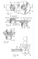
- a substrate 10 which may be used, is illustrated in Figures 1 and 2.
- Substrate 10 is developed from a single piece of plastic material bifurcated into two connected parts 12 and 14.
- Part 12 includes a generally annular flange 16 having a cylindrical wall 18 depending therefrom.
- Part 14 includes a generally rectangular tab 26 extending from annular flange 16.
- the tab supports a cylindrical wall 28.
- a membrane 30 extends across the cylinder defined by cylindrical wall 28 to define test cavity 32.
- a circular wall segment 40 extends from the opposite side of tab 26 and defines annular recess 34.
- Parts 12 and 14 are mated to one another by bending tab 26 in the area defined by dashed lines 36 and 38. To facilitate bending, the cross-section of this protion of the tab may be reduced, as illustrated in Figure 2.
- wall segment 40 of part 14 interiorly mates with annular recess 42 within part 12.
- combing 44 is forced into annular depression 46 of the recess. This mating may be accomplished by a "snap action".
- annular recesses 34 and 40 define a common sealed annular volume.
- Prongs 48, extending from membrane 20 are alternately meshed with prongs 50 extending from membrane 30 in a circular pattern, as illustrated in Figure 1. The tips of each of these prongs positionally correspond with preweakened areas 52 and 54 in membranes 30 and 20, respectively.
- Sample compartment 24 is defined by wall 56 extending from membrane 20 and sealingly mating with wall 58 defined by membrane 30.
- the opposed ends of compartment 24 are defined by the wall circumscribed sections of membranes 20 and 30.
- part 12 excluding flange 16
- part 14, excluding tab 26, is symmetrical about an axis orthogonal to the tab.
- substrate 10 as a whole, will be both statically and dynamically balanced about an axis defined by the axis of cylindrical walls 18 and 28 after parts 12 and 14 have been mated as shown in Figure 3.
- substrate 10 as a unit, will be in balance about the axis of cylindrical walls 18 and 28.
- Flange 16 serves several functions. First, it serves as an element for manipulating substrate 10 between various test stations; it serves as the means through which a spinning motion is imparted to the substrate and it serves as a base upon which identifying information, such as a bar code, is permanently attached.
- Test cavity 22 and control cavity 32 represent segregated cavities within which testing is .effected.
- tests include: (a) blood typing, including forward and reverse typing; (b) antibody screening; and (c) compatibility testing.
- substrate 10 is initially prepared as described to deposit an initial layer of BSA, a second layer of chromic chloride and that appropriate wash/ rinse steps are conducted. Additionally, the various wash/ rinse and inspection steps described are also to be conducted at appropriate intervals during testing.
- the red blood cells to be tested are disposed within sample compartment 24 and discharged therefrom to develop a monolayer upon the test surface in both test cavity 22 and control cavity 32. This first monolayer is then lysed. Thereafter, a known antibody is disposed in the test cavity but not in the control cavity. A second monolayer of reagent (i.e. known) red blood cells is disposed in both the test and control cavities.
- reagent red blood cell solution By using a reagent red blood cell solution, bonding between the antigens of the reagent and the antibody will occur. Should the second monolayer of red blood cells wash away equally rapialy in both the test and control cavities, the test result will be negative as no bonding between the first monolayer of red blood cells and the antibody occurred.
- Reverse typing comtemplates the deposition of reagent red blood cells upon the test surfaces.
- the resulting monolayer of red blood cells is thereafter lysed.
- Serum to be tested and containing natural antibodies is discharged from sample compartment 24 into test cavity 22.
- a second monolayer of reagent red blood cells is deposited upon the serum. During inspection, the second monolayer of red blood cells will be washed away unless a reaction by both the first and second monolayers of red blood cells and the serum occurs.
- the antibody screening test is procedurally similar to reverse typing. But the objectives are different. Reverse typing provides information that is normally used to confirm the results of forward typing. Antibody screening is done to detect the existence of an atypical antibody in the test serum/plasma. The procedure for performing antibody screening will be mechanically similar to the procedure for reverse typing except that the reagent cells will typically be different.
- the compatibility test is directed to the function of mating a patient's blood with a donor's blood to determine whether a reaction therebetween will occur.
- a first monolayer of red blood cells from the donor is deposited in the test cavity and lysed.
- a sample of the patient's serum is discharged from sample compartment 24 into the test cavity.
- a second monolayer of blood cells from the donor are deposited in the test cavity. If, during the washing and inspection steps, the second monolayer is washed away, the results of the test will be negative.
- the following description of the apparatus will be made with reference to forward typing of a sample of red blood cells.
- the red blood cell sample to be typed are channeled into compartment 24 of part 12 prior to the joining of parts 12 and 14.
- indicia for identification purposes is placed upon flange 16.
- part 14 is mated with part 12 in the manner illustrated in Figure 3.
- pressure relief is provided by the air chamber confined by conical depression 60 in part 14.
- appropriate sterilization of substrate 10 may be performed before filling to insure non-contamination of the sample.
- FIG. 4 is therefore illustrative of only one type of apparatus which may be employed.
- a discharge chute 64 serially discharges each of substrates 10 into a retainingly receiving indentation 66 of a disc 68.
- the substrates are mounted within modules 70.
- Each module in essence, retains a substrate and, in cooperation with a power source, provides a means for imparting rotation to the substrate about an axis superimposed upon the axis of rotation of test and control cavities 22 and 23.
- module 70 includes a wheel 72 secured to a frame 74 by means of a bearing 76.
- wheel 72 is rotatable with respect to frame 74.
- Substrate 10 is attached to the wheel by inserting part 12 through central aperture 78 of the wheel until combing 80 at the extremity of flange 82 seats within annular indentation 84 in annular recess 86 of the wheel.
- the mating may be referred to as a "snap action”.
- rotation of wheel 72 will produce a commensurate rotation of substrate 10 about the common axis extending through test and control cavities 22 and 32.
- Frames 74 includes at the base thereof laterally extending feet 88 and 90, which feet slidably mate with commensurate slots 92 and 94 disposed within a guide way 96.
- the guide way guides modules 70 to each of a plurality of work stations.
- Wheel 72 includes an annular groove 98 in the manner of a pulley for engagement with a drive belt 100. Translation of the drive belt may be effected by pulley 102 or the like. Thereby, translation of drive belt 100 will result in rotation of wheel 72 which in turn will spin substrate 10 during translation of module 7.0 along guide way 96.
- Figure 6 illustrates a representative apparatus for sequentially ejecting a plurality of solutions into the test and control cavities of each substrate mounted within serially aligned modules.
- module 70 mounted within guide way 96, is incrementally translated past a discharge nozzle 104 by translation means (not shown). Simultaneous with the translation of module 70, drive belt 100 engages each wheel within each module to maintain the retained substrate in continuous spinning motion. As each module comes to and is momentarily stopped at discharge nozzle 104, a solution is discharged into the test and control cavities of the substrate. Thereafter, the module continues along guide way 96 to further dishcharge nozzles or other apparatus performing one of the steps of the testing process.
- Preparation of the substrate surfaces is very important in order to obtain sufficient reliability of the test process.
- the objective of such surface preparation is to ensure an adhesive-like bond between the substrate surface and the first monolayer of blood cells that will be laid onto the substrate surface.
- One such surface preparation is described to follow.
- Other forms of surface preparation may be provided onto the apparatus described in this disclosure.
- Substrate plastic materials such as polycarbonate, polystyrene, acrylic, mylar and others, appear to have an affinity (presumably by hydrophilic processes) for creating a reasonably strong bond with a layer of bovine serum albumin (hereinafter referred to as "BSA").
- BSA bovine serum albumin
- a solution of BS A which is electronegative, is gently deposited on the surface of the test and control cavities by injection thereinto through a discharge nozzle 104 while the substrate is spinning. Thereafter, all excess BSA is washed away by injecting a quantity of normal saline solution through a nozzle. After washing, a transparent layer of BSA is formed on the cylindrical surfaces of the test and control cavities.
- CrCl 3 chromic chloride
- the CrCl 3 solution is electropositive and will have an affinity for the BSA solution; it will also have an affinity for the red blood cells that will be subsequently placed within the test and control cavities. Excess CrCl 3 is rinsed away with a normal saline solution.
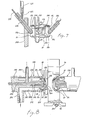
- FIG. 7 there is shown apparatus for effecting the above described solution ejection steps.
- Substrate 10 being mounted within a module 70 (though not shown) is translated to a station placing the substrate intermediate discharge nozzles 104 and 106. These nozzles are brought into operative engagement with control cavity 32 and test cavity 22, respectively, by pivotal movement of a nozzle supporting arm, such as arm 108.
- Each nozzle includes a conduit 110 for conveying a solution from a source of solution to a feeder conduit 112 in fluid communication with chamber 114 and orifice 116.
- a plunger 118 is translatably locatable within chamber 114 to seal orifice 116 and thereby control discharge of the solution through the orifice.
- Each of the two cavities in substrate 10 includes a base section 120, a radially sloping shoulder section 122, a wall section 124, which wall section is in alignment with the axis of rotation of the substrate and a radially inwardly oriented lip section 126. Since the inspection area of the blood sample to be inspected is essentially commensurate with wall section 124, any solution discharged within the cavity should not strike the wall section in order to prevent dislocation or non-continuity within any of the layers which are to be formed upon the wall section. Accordingly, discharge nozzles 104 and 106 are oriented such that any solution discharged through nozzle 116 will strike either base section 120 or shoulder section 122.
- the solution will flow axially across wall section 124 and thereby minimize the disturbance to any existing layers thereupon.
- the slight radially inward orientation of lip 126 insures the formation of layers upon wall section 124 without impeding washing and rinsing of excess solution from within each cavity.
- the extent of radial inwardness of lip 126 may advantageously be used to control the amount of liquid retained within each cavity.
- the washing or rinsing of substrate 10 may be accomplished with the apparatus illustrated in Figure 8.
- Two water nozzles 128 and 130 are positionable by conventional mechanisms (not shown) to place the respective discharge orifices within cavities 32 and 22 of parts 14 and 12, respectively, of substrate 10.
- both water nozzles are duplicates of one another, the following description will primarily be with respect to water nozzle 128, but it is to be understood that the description will apply equally well to water nozzle 130.
- Water nozzle 128 includes a sleeve 132 having an opening 134 dimensioned to non-contactingly circumscribe cylindrical wall 18 of part 14. Interior edge 136 of opening 134 may be beveled, as shown, to accommodate any slight axial misalignment between the water nozzle and the substrate and to guide the sleeve on engagement with part 14.
- a nozzle 138 is disposed concentric with sleeve 132 and extends from a base 140 interior to the sleeve.
- the nozzle includes an axially centered cavity 142 in fluid communication with conduit 144, which conduit is connected to a source of fluid under pressure for metering the flow of fluid discharged from nozzle 138.
- a hollow stud 146 is mounted internal to cavity 142 in axial alignment therewith.
- the stud includes a cone-shaped end piece 148 for developing a cone-shaped spray pattern emanating from orifice 150 at the extremity of cavity 142.
- Passageway 152 extending through stud 146, is connected to a source of air under pressure for directing an air flow through orifice 154 in end piece 148.
- a drain conduit 156 is in fluid communication with annular space 158 disposed intermediate sleeve 132 and nozzle 138. To encourage the flow of fluid and air from within annular space 158 into drain conduit 156, a source of suction or low pressure may be connected to the drain conduit.
- water nozzle 128 is brought into engagement with part 14 such that a lip section 126 is at least partly disposed within opening 134 in circumscribing relationship to nozzle 138.
- the cone-shaped spray of fluid will strike shoulder section 122 in cavity 32; whereby, the impact of the washing/rinsing fluid will not dislodge any existing layers already formed upon wall section 124.
- the air flow emanating from orifice 154 will strike base section 120 and result in turbulent air flow.
- water nozzle 130 will operate in a similar manner to wash/rinse cavity 22 in part 12. After the surfaces in test cavity 22 and control cavity 32 have been prepared to receive and retain the red blood cell sample, the sample must be introduced to the prepared surfaces.
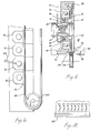
- Substrate 10 is mounted within and attached to wheel 72 of module 70 by circular flange 82 lockingly disposed within mating recess 86, as described above. In this position, flange 16 is brought into contacting supporting relationship with a mating supporting surface of the wheel.
- An axially translatable shaft 160 is positionally centered upon the axis of rotation of substrate 10.
- the shaft supports, through bearing 162, a cylindrical sleeve 164.
- the internal dimension of this sleeve is configured to circumscribe cylindrical wall 18 of part 14 such that edge 166 of the sleeve will bear against the surface of tab 26.
- bearing 162 is employed to allow sleeve 164 to rotate in response to frictional engagement with tab 26.
- part 14 By axially translating shaft 160 by conventional means (not shown), part 14, by applying pressure against the surface of tab 26, is forced toward part 12.
- prongs 50 see also Figures 1 and 2
- prongs 48 will bear against and penetrate weakened areas 52 in base 126 of part 14.
- the prong penetration of the weakened areas is illustrated in Figure 12. As parts 12 and 14 are forced toward one another, the volume of sample compartment 24 will diminish and pressure will be exerted upon the sample disposed therein. As each set of prongs penetrate their respective weakened areas, the rupture occurring at the weakened areas will permit the red blood cell sample to flow through the resulting openings.
- FIG. 10 there is shown a substrate 10 wherein parts 12 and 14 have been physically forced toward one another until tab 26 is adjacent flange 16.
- sample compartment 24 is essentially non-existant and all of the sample formerly contained therein has been discharged into cavities 22 and 32. Because of the sealed relationship of the prongs and ruptured weakened areas, the essential mating of the opposed sides of compartment 24 and the centrifugal force which urges flow of the sample to the radial extremities of the respective cavities, there exists very little probability of cross-flow of the sample from one cavity to the other. Should such flow occur, the integrity of the test and control samples would be lost. To further limit the probability of any cross-flow of the sample, the prongs and mating weakened areas can be somewhat modified to effect a seal at the ruptured openings. Such a seal is illustrated in Figure 11.
- the prongs instead of extending from a planar surface may be configured to extend from the planar surface of. a square-shaped pedestal 168..
- a planar surface circumscribing prong 50 and oriented orthogonal to the longitudinal axis of the prong is developed.
- Weakened area 54 may be manufactured to include a groove 170 in a square configuration duplicative of the four edges of pedestal 168 adjacent the base of the prong.
- groove 170 will engage the corresponding edge 172 of pedestal 168 and effect a seal therebetween.
- the groove may also serve a secondary purpose of encouraging the folding back of ruptured sections 174 of weakened area 54.
- the groove may be replaced by a ridge to bear against the planar surface of the pedestal to effect a seal.
- the sample of red blood cells is deposited in the test and control cavities by operation of the apparatus described above.
- the red blood cells which are electronegative, have an affinity for the chromic chloride and reasonably tight bonds will be formed therewith. Should a relatively thick layer of blood cells settle upon wall section 126, only those cells close to the surface of the wall section will have a chance to form bonds with the chromic chloride layer. A subsequent wash/rinse with a normal saline solution will remove all but the surface layer of the red blood cells. Such a layer is termed "monolayer" because only one layer of cells will remain after washing/rinsing.
- Red blood cells are disc-like in shape and tend to lay flat on a surface. Being circular in shape, they do not cover a surface perfectly, but by simple calculation it is evident that approximately ninety percent coverage will occur.
- An objective of the blood typing is to treat the sample of red blood cells with a known antibody and test for a gg lu- tination.
- the solution containing the know antibody is called “antiserum” or “antisera”.
- a specific antiserum might be called “anti-A” because it contains antibodies that react with type A red blood cells.
- the antisera treatment procedure includes the step of applying the antisera with antibodies to test cavity 22 and the same serum but without antibodies to control cavity 32. Any excess serum in either cavity is discharged off the edge of lip section 126 by the rotary motion of the substrate. After a waiting period, the antibodies in the serum lodged within the test cavity will react with the antigens on the red blood cells therein to form bonds. If no antigens are present which are of the type that will react with the antibodies, no bonds will be formed.
- the number of antigens of a given type on the surface of a red blood cell is variable. The presence of many antigens will produce a "strongly positive” reaction but to test for a weak reaction (i.e. few antigens) enough time must be allowed for a reaction to occur. To optimize the procedure, a greater concentration of antibodies in the antisera in the test cavity will optimize the treatment procedure.
- lysing If the membrane of a red blood cell ruptures, the red coloration (hemoglobin) will escape; this process is called "lysing".
- lysing To lyse a cell means to bleach the cell of its red colour. Lysing is accomplished by exposing red blood cells to an environment that is significantly less saline than normal blood as such a difference in salinity will cause rupture of the membrane. Distilled water, because it lacks salt, works very well for this purpose.
- Bleaching or lysing of the red blood cell layer deposited on the chromic chloride layer is accomplished by introducing distilled water into test cavity 22 and control cavity 32 by means such as discharge nozzles.and 104 and 106. On contact with distilled water, the red blood cells will rupture the, cell membranes and the hemoglobin will be released. The hemoglobin is rinsed away with a normal saline solution.
- red blood cells After lysing, the red blood cells will remain adhered to the chromic chloride layer but they are essentially transparent. These red blood cells are called "ghost cells"; however, they retain the antibody-antigen bonds formed during the antisera treatment procedure.
- a second layer of blood cells is formed in the test and control cavity by applying a prepared amount of the reagent red blood cells to the wall sections of the two cavities.
- This second layer of red blood cells are known to react with or form a bond with the antibodies deposited upon the first layer of red blood cells.
- the antibodies thus act like a form of glue to bind the second layer of red blood cells with the antibodies.
- the absence of antibodies means that no bonding of the second layer will occur and subsequent testing for such bonding will produce a negative test result in the control cavity.
- the first and second layers will not be bonded to one another by the antisera.
- the test procedures to be later conducted will determine not only whether the second layer of red blood cells will adhere to the ghost cell layer but also how firm the adhesion may be.
- Preparation of the second red blood cell solution may include the dilution of some of the sample red blood cells in a glycine saline solution.
- Glycine saline solution has a lower ionic strength than a normal saline solution which enables the red blood cells in solution to approach each other more closely.
- the cells in the second blood cell layer can move closer to the ghost cells which allows the antibodies to attach more easily to an antigen on a cell in the second red blood cell solution. (The exact mechanism for this behavior is not clearly understood, but the effect appears to be as described).
- a 20 to 1 solution of the red blood cells in a glycine saline solution is prepared. This ratio effectively reduces the volume of the red blood cells-in solution to about 0.25%.
- the prepared solution is introduced to the test and control cavities to allow bonding with the layer of antisera.
- PVP polyvinyl pyrrolidine
- the PVP can be added either after the second layer of red blood cells is essentially formed or before the introduction of the second layer.
- a mixture of blood cells and PVP may also be used.
- a centrifugal force i.e. centrifuging
- the blood cells would otherwise remain suspended in PVP.
- care must be exercised during application of the PVP to avoid dislocation of the second layer of red blood cells. Because of the forces attendant the PVP due to the spinning substrate and the limited radial inward excursion of lip section 126, excess PVP will be automatically discharged from within the respective cavities.
- the second layers of red blood cells in the test and control cavities are not lysed and they remain colored by the hemoglobin within the cells.
- the resulting effect is that of a light pink color visible to the eye.
- the absence of coloration would indicate that the second layer of red blood cells is absent.
- the cavities are washed/rinsed to purge the cavities of any non-bonded second layer of red blood cells.
- the first method entails visual inspection of the test and control cavities.
- the control cavity should appear to have a transparent mass deposited upon wall section 126.
- a pink color attendant wall section 126 of the test cavity would indicate the presence of a bonded second layer of red blood cells and the test would provide a positive result.
- a second method comtemplates the collection of the rinse solution from the test and control cavities.
- a subsequent test for optical density of the rinse is made by use of a spectrophotometer.
- a pink rinse from the test cavity would be indicative of a negative test result as the second layer of red blood cells would not have become bonded to the underlying layer of red blood cells.
- a third method incorporates the washing of the cavities with a continuous flow of fluid while a change in the optical density (color) of each wall section * is monitored.
- This method is performed by employing a light source and special optics for passing a beam of light through the wall sections to a detector. The output of the detector is chart recorded or may be used as data input to a data analyzer.
- the third method is of principal interest because it provides quantitative information directly from the wall sections under test. It also lends itself to automation. Moreover, the special optics required and attendant detection systems are well developed and are available from commercial sources.
- the greater or lesser degree of existence of adhering red cells in the test cavity is an indicator of the degree of antigen-antibody reaction; and, the degree of adhesion, that is how rapidly the cells wash away, is an indication of the strength of the reaction.
- the resulting structure will be similar to that illustrated in Figure 12. That is, the layer of BSA on wall section 126 of the substrate will provide an adhering surface for the CrCl 3 . The latter in turn acts as an adherent for the first monolayer of red blood cells (1-RBC). The antigens of 1-RBC will bond with the antibody and the latter will bond with the antigen of the second monolayer of red blood cells (2-RBC). Thereby, the two monolayers will sandwich the antibody therebetween.
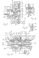
- Water nozzles 176 and 178 are closely related in structure to earlier described water nozzles 128 and 130. Where common elements exist, like reference numerals have been employed.
- the purpose for washing wall sections 126 in test cavity 22 and control cavity 32 is that of determining the color intensity and strength of the bond formed between the layers of bonded red blood cells.
- the purpose, of course, of employing a control cavity which purposely does not include bonds between the two red blood cell layers is to provide a basis for comparing the color and color persistence within the test cavity with that of the control cavity. Accordingly, agitation of the second red blood cell layer is welcomed.
- a source of fluid under pressure is introduced through conduit 144 into annular cavity 142.
- a stud 180 is concentrically disposed within the annular cavity and includes a cone-shaped end piece 182 disposed at orifice 150 of the annular cavity.
- the flared end 184 of nozzle 138 in combination with end piece 182 produces a cone-shaped spray pattern which strikes shoulder section 122 within each of cavities 22 and 23. Therefrom, and because of the spinning motion of substrate 10, the fluid flows across wall section 126 onto lip section 124 and is discharged therefrom.
- a shroud 186 is concentric with cylindrical wall 18 of substrate 10 and includes radially inwardly oriented lip 1-88.
- lip 188 is in close proximity to or lightly bears against the exterior surface of lip section 124 to effect a relatively good seal therebetween. Thereby, this seal, in combination with the vacum developed within annular space 158 by the suction acting through conduit 156 will draw fluid off lip section 124 into conduit 156 with little leakage intermediate the substrate and shroud 186.
- a source of light is introduced anterior of cavities 22 and 32 approximate to wall section 126 by light conductor 190.
- a mirror 192 or other means may be employed to direct the light essentially orthogonal to wall. section 126. Any light passing through wall section 126 impinges upon mirror surface 194 or other reflecting means to direct the received light into light conductor 196.
- Both light conductor 190 and light conductor 196 may be attached to light conducting fiber optic cables 198 and 200. These cables in turn are connected, respectively, to a source of light and light detector means.
- a bar code or similar mechanically, electrically or optically readable identification indicia may be disposed upon flange 16 or tab 26 to identify each substrate.
- a sensor such as sensor 202, may be attached to frame 204. The location of sensor 202 is commensurate with the position of the indicia upon either flange 16 or tab 26 such that as substrate 10 rotates, the indicia will travel past the sensor at each revolution.
- the information sensed or detected by sensor 202 is conveyed to appropriate deciphering equipment by conduit 206.
- sensor 202 may be an optical detector which generates optical signals conveyed to deciphering equipment by a bundle of fiber optic elements disposed within or forming conduit 206.
- a second monolayer of reagent or unknown (depending upon whether the antibody is unknown or known, respectively) red blood cells are deposited upon the antibody to determine which bands exhibit a reddish color and thereby reflect bonding between the first and second monolayers. Analysis of these results will provide information pertinent to identification of the antibody or the second layer of red blood cells.
- a plurality of tests can be performed simultaneously with a known antibody and unknown second layer of red blood cells or a known antibody and an unknown second layer of red blood cells.
- both the test and control cavities could be in the form of elongated cylindrical surfaces separated by a diametric membrane and wherein the bands of the first monolayer of red blood cells have been deposited. Thereafter, the operation, as described above would be duplicated: It is envisioned that some modification of both the specimen injecting nozzles and the washing/rinsing nozzles might have to be effected to disperse the ejected fluids to all of the pre-prepared bands.
Priority Applications (5)
| Application Number | Priority Date | Filing Date | Title |
|---|---|---|---|
| US06/016,805 US4252538A (en) | 1979-03-02 | 1979-03-02 | Apparatus and method for antibody screening, typing and compatibility testing of red blood cells |
| AU64926/80A AU6492680A (en) | 1979-03-02 | 1980-11-28 | Apparatus for blood ab screening typing + compatability |
| ZA00807662A ZA807662B (en) | 1979-03-02 | 1980-12-08 | Apparatus and method for antibody screening typing and compatibility testing of red blood cells |
| EP80304448A EP0054087A1 (de) | 1979-03-02 | 1980-12-10 | Verfahren und Vorrichtung zur Untersuchung und Bestimmung von Antikörpern und zur Verträglichkeitsbestimmung von roten Blutzellen |
| BR8100378A BR8100378A (pt) | 1979-03-02 | 1981-01-23 | Aparelho e processo para ensaios de separacao,classificacao e compatibilidade de celulas vermelhas do sangue |
Applications Claiming Priority (4)
| Application Number | Priority Date | Filing Date | Title |
|---|---|---|---|
| US06/016,805 US4252538A (en) | 1979-03-02 | 1979-03-02 | Apparatus and method for antibody screening, typing and compatibility testing of red blood cells |
| AU64926/80A AU6492680A (en) | 1979-03-02 | 1980-11-28 | Apparatus for blood ab screening typing + compatability |
| EP80304448A EP0054087A1 (de) | 1979-03-02 | 1980-12-10 | Verfahren und Vorrichtung zur Untersuchung und Bestimmung von Antikörpern und zur Verträglichkeitsbestimmung von roten Blutzellen |
| BR8100378A BR8100378A (pt) | 1979-03-02 | 1981-01-23 | Aparelho e processo para ensaios de separacao,classificacao e compatibilidade de celulas vermelhas do sangue |
Publications (1)
| Publication Number | Publication Date |
|---|---|
| EP0054087A1 true EP0054087A1 (de) | 1982-06-23 |
Family
ID=32512367
Family Applications (1)
| Application Number | Title | Priority Date | Filing Date |
|---|---|---|---|
| EP80304448A Withdrawn EP0054087A1 (de) | 1979-03-02 | 1980-12-10 | Verfahren und Vorrichtung zur Untersuchung und Bestimmung von Antikörpern und zur Verträglichkeitsbestimmung von roten Blutzellen |
Country Status (5)
| Country | Link |
|---|---|
| US (1) | US4252538A (de) |
| EP (1) | EP0054087A1 (de) |
| AU (1) | AU6492680A (de) |
| BR (1) | BR8100378A (de) |
| ZA (1) | ZA807662B (de) |
Cited By (6)
| Publication number | Priority date | Publication date | Assignee | Title |
|---|---|---|---|---|
| FR2586815A1 (fr) * | 1985-09-04 | 1987-03-06 | Lacaille Yves | Dispositif pour la determination d'un groupe sanguin |
| WO1987001461A1 (fr) * | 1985-09-04 | 1987-03-12 | Yves Lacaille | Dispositif pour la determination d'un groupe sanguin |
| DE4019299C1 (de) * | 1990-06-16 | 1991-08-14 | Uwe Dr.Med. 2300 Kiel De Ballies | |
| WO1994018572A1 (es) * | 1993-02-12 | 1994-08-18 | Centro De Transfusiones De La Comunidad Valenciana | Procedimiento para la deteccion de los sistemas abo y rh en hematies y anti-a y anti-b en suero o plasma |
| EP0678745A1 (de) * | 1994-04-22 | 1995-10-25 | Scibiex (Sarl) | Vorrichtung und Verfahren zur immunologischen Analyse |
| EP0779103A1 (de) * | 1995-12-13 | 1997-06-18 | Lider S.à.r.l. | Vorrichtung zur visuellen Untersuchung einer Flüssigkeit durch Vermengen mit einer flüssigen Reagens |
Families Citing this family (26)
| Publication number | Priority date | Publication date | Assignee | Title |
|---|---|---|---|---|
| CA1152353A (en) * | 1980-05-05 | 1983-08-23 | Georges Revillet | Multicuvette rotor for analyser |
| US4410630A (en) * | 1981-12-11 | 1983-10-18 | The United States Of America As Represented By The Department Of Health And Human Services | Lysis filtration culture chamber |
| US4608246A (en) * | 1983-03-10 | 1986-08-26 | Immucor, Inc. | Testing for a blood group immunological reaction |
| GB8500294D0 (en) * | 1985-01-07 | 1985-02-13 | Martin W J | Automatic chemistry machine |
| US4708850A (en) * | 1985-05-20 | 1987-11-24 | Abbas Husain | Self-contained portable apparatus for blood typing |
| US4974462A (en) * | 1988-03-17 | 1990-12-04 | Millipore Corporation | Filter punch and filter collection system |
| US5759774A (en) * | 1988-05-18 | 1998-06-02 | Cobe Laboratories, Inc. | Method of detecting circulating antibody types using dried or lyophilized cells |
| CA2011099A1 (en) * | 1989-04-19 | 1990-10-19 | Stephen C. Wardlaw | Determination of lymphocyte reactivity to specific antigens in blood |
| US5939022A (en) * | 1997-12-09 | 1999-08-17 | Pharmacia Biotech, Inc. | Article for transporting biological samples during analysis |
| CN100533147C (zh) * | 2000-05-26 | 2009-08-26 | 松下电器产业株式会社 | 生物传感器 |
| US6889468B2 (en) * | 2001-12-28 | 2005-05-10 | 3M Innovative Properties Company | Modular systems and methods for using sample processing devices |
| US20070054405A1 (en) * | 2003-10-23 | 2007-03-08 | Ortho-Clinical Diagnostics, Inc. | Patient sample classification based upon low angle light scattering |
| US7763210B2 (en) * | 2005-07-05 | 2010-07-27 | 3M Innovative Properties Company | Compliant microfluidic sample processing disks |
| US7754474B2 (en) | 2005-07-05 | 2010-07-13 | 3M Innovative Properties Company | Sample processing device compression systems and methods |
| US7323660B2 (en) * | 2005-07-05 | 2008-01-29 | 3M Innovative Properties Company | Modular sample processing apparatus kits and modules |
| US20080280310A1 (en) * | 2007-05-09 | 2008-11-13 | Louis Panagopoulos | Testing for Blood Group Immunological Reaction Without the Use of Anti-Human Globulin |
| USD667561S1 (en) | 2009-11-13 | 2012-09-18 | 3M Innovative Properties Company | Sample processing disk cover |
| US20110117607A1 (en) * | 2009-11-13 | 2011-05-19 | 3M Innovative Properties Company | Annular compression systems and methods for sample processing devices |
| USD638951S1 (en) | 2009-11-13 | 2011-05-31 | 3M Innovative Properties Company | Sample processing disk cover |
| US8834792B2 (en) | 2009-11-13 | 2014-09-16 | 3M Innovative Properties Company | Systems for processing sample processing devices |
| USD638550S1 (en) | 2009-11-13 | 2011-05-24 | 3M Innovative Properties Company | Sample processing disk cover |
| USD672467S1 (en) | 2011-05-18 | 2012-12-11 | 3M Innovative Properties Company | Rotatable sample processing disk |
| WO2012158988A1 (en) | 2011-05-18 | 2012-11-22 | 3M Innovative Properties Company | Systems and methods for valving on a sample processing device |
| ES2755078T3 (es) | 2011-05-18 | 2020-04-21 | Diasorin S P A | Sistemas y métodos para medición volumétrica en un dispositivo de procesamiento de muestra |
| ES2870874T3 (es) | 2011-05-18 | 2021-10-27 | Diasorin S P A | Sistemas y métodos para detectar la presencia de un volumen seleccionado de material en un dispositivo de procesamiento de muestra |
| EP2969177A1 (de) | 2013-03-15 | 2016-01-20 | Massachusetts Institute of Technology | Abscheidung und abbildung von teilchen auf planaren substraten |
Citations (5)
| Publication number | Priority date | Publication date | Assignee | Title |
|---|---|---|---|---|
| US3705048A (en) * | 1970-11-06 | 1972-12-05 | Perkin Elmer Corp | Clinical spinner |
| DE2417338A1 (de) * | 1966-12-22 | 1974-10-24 | Ortho Pharma Corp | Vorrichtung zum mischen von reagenzien |
| US4066407A (en) * | 1976-12-16 | 1978-01-03 | Vincent Lupica | Body fluid testing system and process |
| US4092120A (en) * | 1975-12-08 | 1978-05-30 | Osmo Antero Suovaniemi | Method and apparatus for establishing fecal occult blood |
| US4197088A (en) * | 1977-09-23 | 1980-04-08 | Akro-Medic Engineering, Inc. | Method for qualitative and quantitative determination of immunological reactions |
Family Cites Families (9)
| Publication number | Priority date | Publication date | Assignee | Title |
|---|---|---|---|---|
| SE335630B (de) * | 1964-08-31 | 1971-06-01 | H Unger | |
| US3540857A (en) * | 1968-01-22 | 1970-11-17 | Beckman Instruments Inc | Sample capsule and filtering mechanism |
| US3532470A (en) * | 1968-01-22 | 1970-10-06 | Beckman Instruments Inc | Sample holder with centrifugation means |
| US3826622A (en) * | 1969-07-30 | 1974-07-30 | Rohe Scientific Corp | Containers for use in an automated centrifuge |
| US3715189A (en) * | 1970-06-15 | 1973-02-06 | Secretary Of The Treasury | Qualitative analysis device |
| US3713780A (en) * | 1971-02-01 | 1973-01-30 | Becton Dickinson Co | Apparatus for chemical testing |
| US3771965A (en) * | 1971-04-23 | 1973-11-13 | R Grams | Biological fluid sampling apparatus |
| US4119407A (en) * | 1976-03-08 | 1978-10-10 | Bio-Dynamics, Inc. | Cuvette with reagent release means |
| US4055394A (en) * | 1976-10-18 | 1977-10-25 | Akzona Incorporated | Diagnostic test card |
-
1979
- 1979-03-02 US US06/016,805 patent/US4252538A/en not_active Expired - Lifetime
-
1980
- 1980-11-28 AU AU64926/80A patent/AU6492680A/en not_active Abandoned
- 1980-12-08 ZA ZA00807662A patent/ZA807662B/xx unknown
- 1980-12-10 EP EP80304448A patent/EP0054087A1/de not_active Withdrawn
-
1981
- 1981-01-23 BR BR8100378A patent/BR8100378A/pt unknown
Patent Citations (6)
| Publication number | Priority date | Publication date | Assignee | Title |
|---|---|---|---|---|
| DE2417338A1 (de) * | 1966-12-22 | 1974-10-24 | Ortho Pharma Corp | Vorrichtung zum mischen von reagenzien |
| GB1459903A (en) * | 1966-12-22 | 1976-12-31 | Ortho Pharma Corp | Mixing device |
| US3705048A (en) * | 1970-11-06 | 1972-12-05 | Perkin Elmer Corp | Clinical spinner |
| US4092120A (en) * | 1975-12-08 | 1978-05-30 | Osmo Antero Suovaniemi | Method and apparatus for establishing fecal occult blood |
| US4066407A (en) * | 1976-12-16 | 1978-01-03 | Vincent Lupica | Body fluid testing system and process |
| US4197088A (en) * | 1977-09-23 | 1980-04-08 | Akro-Medic Engineering, Inc. | Method for qualitative and quantitative determination of immunological reactions |
Cited By (12)
| Publication number | Priority date | Publication date | Assignee | Title |
|---|---|---|---|---|
| FR2586815A1 (fr) * | 1985-09-04 | 1987-03-06 | Lacaille Yves | Dispositif pour la determination d'un groupe sanguin |
| WO1987001461A1 (fr) * | 1985-09-04 | 1987-03-12 | Yves Lacaille | Dispositif pour la determination d'un groupe sanguin |
| US4948562A (en) * | 1985-09-04 | 1990-08-14 | Lacaille Yves M | Device for determining a blood group |
| DE4019299C1 (de) * | 1990-06-16 | 1991-08-14 | Uwe Dr.Med. 2300 Kiel De Ballies | |
| EP0462463A1 (de) * | 1990-06-16 | 1991-12-27 | Ballies, Uwe, Dr. med. | Verfahren zur Bestimmung von Blutgruppen |
| WO1994018572A1 (es) * | 1993-02-12 | 1994-08-18 | Centro De Transfusiones De La Comunidad Valenciana | Procedimiento para la deteccion de los sistemas abo y rh en hematies y anti-a y anti-b en suero o plasma |
| ES2066713A1 (es) * | 1993-02-12 | 1995-03-01 | Transfusion De La Comunidad Va | Metodo para la deteccion de los sistemas abo y rh en hematies. |
| EP0678745A1 (de) * | 1994-04-22 | 1995-10-25 | Scibiex (Sarl) | Vorrichtung und Verfahren zur immunologischen Analyse |
| FR2719122A1 (fr) * | 1994-04-22 | 1995-10-27 | Scibiex Sarl | Dispositif et procédé d'analyse immunologique. |
| US5746975A (en) * | 1994-04-22 | 1998-05-05 | Scibiex (Sarl) | Apparatus for immunological analysis |
| EP0779103A1 (de) * | 1995-12-13 | 1997-06-18 | Lider S.à.r.l. | Vorrichtung zur visuellen Untersuchung einer Flüssigkeit durch Vermengen mit einer flüssigen Reagens |
| FR2742544A1 (fr) * | 1995-12-13 | 1997-06-20 | Lider Sarl | Procede de controle visuel d'un liquide par melange avec un liquide reactif et dispositif pour sa mise en oeuvre |
Also Published As
| Publication number | Publication date |
|---|---|
| AU6492680A (en) | 1982-06-03 |
| BR8100378A (pt) | 1982-09-21 |
| US4252538A (en) | 1981-02-24 |
| ZA807662B (en) | 1981-12-30 |
Similar Documents
| Publication | Publication Date | Title |
|---|---|---|
| US4252538A (en) | Apparatus and method for antibody screening, typing and compatibility testing of red blood cells | |
| JP3361097B2 (ja) | 分析用ローターのための試薬容器 | |
| US3497320A (en) | Automated chemical analyzer | |
| US4918025A (en) | Self contained immunoassay element | |
| US6024883A (en) | Method for blood analyses | |
| CA1248873A (en) | Particles and procedures for the determination of antigens and/or antibodies using the particles | |
| CN101603967B (zh) | 快速检测人ABO/Rh/MN血型的方法及试剂盒 | |
| HU206918B (en) | Analytical detecting instrument | |
| US20140033809A1 (en) | Disposable cartridge for preparing a sample fluid containing cells for analysis | |
| JPH07505473A (ja) | 自動連続ランダム・アクセス分析システムおよびその構成要素 | |
| JPH03504465A (ja) | 検定要素 | |
| CN109030812A (zh) | 一种基于免疫检测和生化检测的微流控芯片、检测仪和检测方法 | |
| CN103439518B (zh) | 一种血液abd定型快速综合检测卡 | |
| CN112638530A (zh) | 微流体转子设备 | |
| CN208607231U (zh) | 一种基于免疫检测和生化检测的微流控芯片和检测仪 | |
| CN112601612B (zh) | 用于检查微流体转子设备的系统和方法 | |
| KR102565185B1 (ko) | 마이크로 유체 회전자 디바이스 | |
| CN112638531B (zh) | 微流体转子设备 | |
| KR20010033821A (ko) | 생성 시료에 존재하는 적어도 하나 이상의 특정 성분을투약하기 위한 수단, 방법 및 이 방법을 수행하는 장치 | |
| CN103599817A (zh) | 免疫学化验系统和方法 | |
| CA2350355C (en) | Container for holding biologic fluid for analysis | |
| EP0749572B1 (de) | Prüfröhrchen und gerät zur durchführung von immunohämatologischen analyse von blut und anderen biologischen flüssigkeiten | |
| SE460564B (sv) | Testsats och foerfarande foer immunanalys med prefabricerade komplex av maerkt antikropp och analytspecifik antikropp | |
| JP3162172B2 (ja) | 自動血液分析装置 | |
| JPS61118662A (ja) | 免疫学的自動分析方法 |
Legal Events
| Date | Code | Title | Description |
|---|---|---|---|
| PUAI | Public reference made under article 153(3) epc to a published international application that has entered the european phase |
Free format text: ORIGINAL CODE: 0009012 |
|
| AK | Designated contracting states |
Designated state(s): CH DE FR GB IT NL SE |
|
| STAA | Information on the status of an ep patent application or granted ep patent |
Free format text: STATUS: THE APPLICATION IS DEEMED TO BE WITHDRAWN |
|
| 18D | Application deemed to be withdrawn |
Effective date: 19830602 |
|
| RIN1 | Information on inventor provided before grant (corrected) |
Inventor name: BARR, LAWRENCE D. |