EP0053564B1 - Process for monitoring the diaphragm permeability during the electrolytic preparation of polyvalent metals, and electrolysis cell for carrying out this process - Google Patents
Process for monitoring the diaphragm permeability during the electrolytic preparation of polyvalent metals, and electrolysis cell for carrying out this process Download PDFInfo
- Publication number
- EP0053564B1 EP0053564B1 EP81420172A EP81420172A EP0053564B1 EP 0053564 B1 EP0053564 B1 EP 0053564B1 EP 81420172 A EP81420172 A EP 81420172A EP 81420172 A EP81420172 A EP 81420172A EP 0053564 B1 EP0053564 B1 EP 0053564B1
- Authority
- EP
- European Patent Office
- Prior art keywords
- diaphragm
- electrolysis
- electrolyte
- titanium
- permeability
- Prior art date
- Legal status (The legal status is an assumption and is not a legal conclusion. Google has not performed a legal analysis and makes no representation as to the accuracy of the status listed.)
- Expired
Links
- 238000005868 electrolysis reaction Methods 0.000 title claims abstract description 35
- 229910052751 metal Inorganic materials 0.000 title claims abstract description 23
- 239000002184 metal Substances 0.000 title claims abstract description 23
- 230000035699 permeability Effects 0.000 title claims abstract description 22
- 238000000034 method Methods 0.000 title claims abstract description 21
- 230000008569 process Effects 0.000 title claims abstract description 16
- 150000002739 metals Chemical class 0.000 title claims abstract description 10
- 238000002360 preparation method Methods 0.000 title claims description 15
- 238000012544 monitoring process Methods 0.000 title 1
- 229910052719 titanium Inorganic materials 0.000 claims abstract description 28
- 239000003792 electrolyte Substances 0.000 claims description 25
- 229910052735 hafnium Inorganic materials 0.000 claims description 5
- 229910052758 niobium Inorganic materials 0.000 claims description 5
- 229910052715 tantalum Inorganic materials 0.000 claims description 5
- 229910052720 vanadium Inorganic materials 0.000 claims description 5
- 229910052726 zirconium Inorganic materials 0.000 claims description 5
- 229910001507 metal halide Inorganic materials 0.000 claims description 2
- 150000005309 metal halides Chemical class 0.000 claims description 2
- 239000010936 titanium Substances 0.000 abstract description 32
- RTAQQCXQSZGOHL-UHFFFAOYSA-N Titanium Chemical compound [Ti] RTAQQCXQSZGOHL-UHFFFAOYSA-N 0.000 abstract description 26
- 150000004820 halides Chemical class 0.000 abstract description 6
- 238000004090 dissolution Methods 0.000 abstract description 3
- 238000004519 manufacturing process Methods 0.000 abstract description 3
- 229910003074 TiCl4 Inorganic materials 0.000 abstract 1
- XJDNKRIXUMDJCW-UHFFFAOYSA-J titanium tetrachloride Chemical compound Cl[Ti](Cl)(Cl)Cl XJDNKRIXUMDJCW-UHFFFAOYSA-J 0.000 abstract 1
- 238000000151 deposition Methods 0.000 description 10
- 230000008021 deposition Effects 0.000 description 10
- 150000002500 ions Chemical class 0.000 description 8
- PXHVJJICTQNCMI-UHFFFAOYSA-N Nickel Chemical compound [Ni] PXHVJJICTQNCMI-UHFFFAOYSA-N 0.000 description 6
- -1 halogen ions Chemical class 0.000 description 5
- 239000003513 alkali Substances 0.000 description 4
- 229910052784 alkaline earth metal Inorganic materials 0.000 description 4
- 239000010955 niobium Substances 0.000 description 4
- 239000011148 porous material Substances 0.000 description 4
- 229910001209 Low-carbon steel Inorganic materials 0.000 description 3
- 238000010586 diagram Methods 0.000 description 3
- 229910052736 halogen Inorganic materials 0.000 description 3
- QCWXUUIWCKQGHC-UHFFFAOYSA-N Zirconium Chemical compound [Zr] QCWXUUIWCKQGHC-UHFFFAOYSA-N 0.000 description 2
- 150000001342 alkaline earth metals Chemical class 0.000 description 2
- 230000015572 biosynthetic process Effects 0.000 description 2
- 229910052801 chlorine Inorganic materials 0.000 description 2
- 239000000460 chlorine Substances 0.000 description 2
- 150000001805 chlorine compounds Chemical class 0.000 description 2
- 238000009792 diffusion process Methods 0.000 description 2
- 238000009826 distribution Methods 0.000 description 2
- 230000000694 effects Effects 0.000 description 2
- VBJZVLUMGGDVMO-UHFFFAOYSA-N hafnium atom Chemical compound [Hf] VBJZVLUMGGDVMO-UHFFFAOYSA-N 0.000 description 2
- 150000002367 halogens Chemical class 0.000 description 2
- 238000002347 injection Methods 0.000 description 2
- 239000007924 injection Substances 0.000 description 2
- 239000000463 material Substances 0.000 description 2
- 238000005259 measurement Methods 0.000 description 2
- 229910052759 nickel Inorganic materials 0.000 description 2
- GUCVJGMIXFAOAE-UHFFFAOYSA-N niobium atom Chemical compound [Nb] GUCVJGMIXFAOAE-UHFFFAOYSA-N 0.000 description 2
- 239000012466 permeate Substances 0.000 description 2
- 230000009467 reduction Effects 0.000 description 2
- 239000000243 solution Substances 0.000 description 2
- GUVRBAGPIYLISA-UHFFFAOYSA-N tantalum atom Chemical compound [Ta] GUVRBAGPIYLISA-UHFFFAOYSA-N 0.000 description 2
- LEONUFNNVUYDNQ-UHFFFAOYSA-N vanadium atom Chemical compound [V] LEONUFNNVUYDNQ-UHFFFAOYSA-N 0.000 description 2
- OKTJSMMVPCPJKN-UHFFFAOYSA-N Carbon Chemical compound [C] OKTJSMMVPCPJKN-UHFFFAOYSA-N 0.000 description 1
- ZAMOUSCENKQFHK-UHFFFAOYSA-N Chlorine atom Chemical compound [Cl] ZAMOUSCENKQFHK-UHFFFAOYSA-N 0.000 description 1
- 229910000831 Steel Inorganic materials 0.000 description 1
- 230000009471 action Effects 0.000 description 1
- 229910045601 alloy Inorganic materials 0.000 description 1
- 239000000956 alloy Substances 0.000 description 1
- 239000002585 base Substances 0.000 description 1
- 230000033228 biological regulation Effects 0.000 description 1
- 238000006243 chemical reaction Methods 0.000 description 1
- 239000010941 cobalt Substances 0.000 description 1
- 229910017052 cobalt Inorganic materials 0.000 description 1
- GUTLYIVDDKVIGB-UHFFFAOYSA-N cobalt atom Chemical group [Co] GUTLYIVDDKVIGB-UHFFFAOYSA-N 0.000 description 1
- 238000004891 communication Methods 0.000 description 1
- 239000002131 composite material Substances 0.000 description 1
- 230000007797 corrosion Effects 0.000 description 1
- 238000005260 corrosion Methods 0.000 description 1
- 238000005520 cutting process Methods 0.000 description 1
- 230000006378 damage Effects 0.000 description 1
- 238000013461 design Methods 0.000 description 1
- 238000005363 electrowinning Methods 0.000 description 1
- 239000000374 eutectic mixture Substances 0.000 description 1
- 239000004744 fabric Substances 0.000 description 1
- 230000002349 favourable effect Effects 0.000 description 1
- 229910002804 graphite Inorganic materials 0.000 description 1
- 239000010439 graphite Substances 0.000 description 1
- 230000006872 improvement Effects 0.000 description 1
- 230000007246 mechanism Effects 0.000 description 1
- 229910021645 metal ion Inorganic materials 0.000 description 1
- 230000005012 migration Effects 0.000 description 1
- 238000013508 migration Methods 0.000 description 1
- 239000000203 mixture Substances 0.000 description 1
- 239000000047 product Substances 0.000 description 1
- 230000002035 prolonged effect Effects 0.000 description 1
- 230000006798 recombination Effects 0.000 description 1
- 238000005215 recombination Methods 0.000 description 1
- 150000003839 salts Chemical class 0.000 description 1
- 239000010959 steel Substances 0.000 description 1
- 239000013598 vector Substances 0.000 description 1
Images

Classifications
-
- C—CHEMISTRY; METALLURGY
- C25—ELECTROLYTIC OR ELECTROPHORETIC PROCESSES; APPARATUS THEREFOR
- C25C—PROCESSES FOR THE ELECTROLYTIC PRODUCTION, RECOVERY OR REFINING OF METALS; APPARATUS THEREFOR
- C25C3/00—Electrolytic production, recovery or refining of metals by electrolysis of melts
- C25C3/26—Electrolytic production, recovery or refining of metals by electrolysis of melts of titanium, zirconium, hafnium, tantalum or vanadium
-
- C—CHEMISTRY; METALLURGY
- C25—ELECTROLYTIC OR ELECTROPHORETIC PROCESSES; APPARATUS THEREFOR
- C25C—PROCESSES FOR THE ELECTROLYTIC PRODUCTION, RECOVERY OR REFINING OF METALS; APPARATUS THEREFOR
- C25C7/00—Constructional parts, or assemblies thereof, of cells; Servicing or operating of cells
- C25C7/06—Operating or servicing
Definitions
- the process which is the subject of the invention relates to the preparation of polyvalent metals such as titanium, zirconium, hafnium, vanadium, niobium or tantalum by electrolysis in molten salt baths of their halides dissolved in one or more alkali or alkaline earth halides.
- This process applies more particularly to the preparation of titanium by electrolysis of a bath of molten halides.
- This diaphragm must, on the other hand, allow the alkaline or alkaline-earth ions to pass, as well as the halogen ions which transport most of the current.
- this diaphragm In general, the permeability of this diaphragm must be sufficient to allow the circulation of the electrolyte in order to balance the pressures in the two compartments, while making as much as possible an obstacle to the passage of the metal to be deposited, in ionic form. or not towards the anode compartment.
- This structure is preferably made up of a grid or a perforated screen made of nickel or a nickel-based alloy. In order to give it a sufficiently low permeability for it to act as a diaphragm, it is covered with an electrolytic deposit of titanium in the electrolysis cell itself. For this, this structure is connected to the electrical supply circuit of the cell, so as to make it play the role of a cathode. The titanium deposit which then forms partially plugs the holes.
- the FR patent. 2423 555 describes another embodiment of a diaphragm for cells used for the electrolytic preparation of polyvalent metals. These diaphragms are preferably formed by a metallic nickel cloth on which an electrolytic or non-electrolytic deposition of cobalt has been carried out.
- connection between anolyte and catholyte is gradually cut and the diaphragm starts to function like a bipolar electrode. This most often results in destruction of the diaphragm, either by corrosion or by crushing.
- a process has therefore been sought which makes it possible to avoid such drawbacks and, in particular, to considerably extend the life of the diaphragms used for the preparation of polyvalent metals by electrolysis.
- Such a method must also make it possible to maintain a high current yield, both with regard to the deposition of the polyvalent metal at the cathode and with regard to the release of halogen at the anode. Finally, it must make it possible to maintain the voltage at the terminals of the electrolysis cell within the determined limits corresponding to operating conditions close to the optimum.
- the process which is the subject of the invention consists in controlling the permeability of the diaphragm of an electrolysis cell for the preparation of polyvalent metals such as Ti, Zr, Hf, V, Nb and Ta from a electrolyte based on molten metal halides, thanks to the formation of a deposit of the metal to be obtained on this diaphragm, said diaphragm being able to be positively or negatively polarized;
- this process is characterized in that the drop in potential in the electrolyte bath permeating the diaphragm is measured continuously and without interrupting the operation of the electrolysis, and in that a direct electric current is sent into the said diaphragm whose intensity and direction are slaved to the said drop in potential so as to maintain the permeability within determined limits.
- This partial growth or redissolution of a deposit of a polyvalent metal is carried out without interrupting the operation of the electrolysis, continuously or discontinuously at constant or variable speed.
- FIG. 1 is the diagram of a diaphragm electrolysis cell, particularly suitable for the preparation by electrolysis of titanium, the general arrangement of which is similar to that described in the USBM report No. 764S-1972 entitled “Use of composite diaphragm in the Electrowinning of titanium (fig. 1, p. 3).
- This cell comprises a receptacle (1) made of refractory steel heated from the outside by known and not described means which make it possible to bring the electrolyte (2) to a temperature of approximately 550 ° C.
- This consists of a LiCIKCI eutectic mixture containing titanium in solution, in the form of chlorides at a concentration of approximately 1 to 3% by weight of Ti.
- a graphite anode (3) is immersed in the electrolyte and is surrounded by a diaphragm (4). This anode is connected by a rod (5) to the positive pole of a current source, not shown.
- a supply cathode consists of a mild steel tube (6) connected to the negative pole of a current source, not shown. This cathode is supplied with TiCI 4 by the connection tube (7) from an injection system not shown. The end of the tube (6) has a perforated zone (8) also made of mild steel immersed in the electrolyte.
- a mild steel deposition cathode (9) is also connected to the negative pole of the current source.
- a current distributor device, not shown, makes it possible to fix the ratio between the currents I 1 and 1 2 which pass respectively through the supply (6) and deposition (9) cathodes.
- the current flowing through the anode has an intensity 1 equal to I 1 + I 2 .
- an Ni grid is used which has been coated with a Ti deposit by a suitable method, such as that described in the US patent. No. 2,789,943, so as to reduce the permeability to the desired level.
- the amount of TiCl 4 injected through the supply cathode is such that the concentration of Ti dissolved in the electrolyte is preferably maintained in the concentration range of 1 to 3% by weight of Ti.
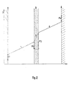
- the diaphragm in Figure 2 shows the distribution of potentials in the electrolysis cell during its operation.
- the potential (P) which exists in the electrolysis cell in operation in the interval between cathode and anode is represented on the ordinate, represented on the abscissa.
- Cathode C, diaphragm D and anode A are shown schematically.
- the straight sections a, b and c respectively represent the potential variations which occur in the catholyte, in the electrolyte which impregnates the diaphragm and in the anolyte.
- the vertical vectors P i , P 2 . P 3 and P 4 respectively represent the potential differences between the cathode, the cathode and anode faces of the diaphragm and the anode with respect to the electrolyte in contact.
- the variation of the potential “b” is equal to the product of 1 (electrolysis current) by R D (resistance of the electrolyte which permeates the diaphragm).
- 1 x R D varies in the opposite direction to the permeability.
- the equilibrium potential of the diaphragm P 3 with respect to the anolyte is defined by the formula:
- the conventions are the same as in the previous one and “a Ti2- anodic represents the activity of Ti2 + ions in the anolyte.
- IR D is therefore a measure of the efficiency of the diaphragm as a means of preventing the diffusion of titanium ions towards the anolyte.
- the diaphragm becomes bipolar and an alkali or alkaline earth deposit appears on the face of the diaphragm opposite the anode.
- the current yield on the anode side then collapses quickly by recombination of the chlorine released at the anode with the alkalis formed.
- chlorine ions are discharged which cause a rapid attack on this diaphragm.
- too high permeability of the diaphragm is undesirable since the diffusion of Ti ions from the catholyte to the anolyte in too large a quantity would lead to too great a reduction in yield.
- the method for controlling the permeability of the diaphragm according to the invention consists in controlling the deposition of titanium which takes place there more or less naturally either with a view to increasing it, or with a view to partially redissolving it, this growth or this redissolution being subject to the variation of the voltage drop across the electrolyte which permeates the diaphragm. It is thus possible, in an extremely simple manner, to choose in advance, according to the characteristics of the cell, a special value of this drop in potential and to keep it within a determined range.
- the potential drop across the diaphragm should be kept below a upper limit, of the order of a volt, which corresponds to the difference between the deposition potential of Ti2 + and that of the alkali or alkaline earth metal.
- a upper limit of the order of a volt, which corresponds to the difference between the deposition potential of Ti2 + and that of the alkali or alkaline earth metal.
- this difference should not exceed the value which corresponds to the discharge of alkaline ions on the diaphragm.
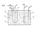
- a particularly advantageous device represented in FIG. 3 consists in connecting the diaphragm to a current source capable of ensuring the passage of this current in both directions, the other pole of this source being connected to the cathode.
- FIG. 3 schematically represents an electrolysis cell whose design derives from that of the cell in FIG. 1.
- the metal electrolysis cell (10) contains the electrolyte (11) whose composition is similar to that described above for the preparation of titanium.
- the anode (12) is surrounded by a diaphragm (15).
- the anode is connected, as usual, to the positive pole of a first current source not shown, whose negative pole is connected to the cathodes.
- the diaphragm is connected either to the positive pole or to the negative pole of a second source of current not shown, the other pole of which is connected to the cathode, and which is capable of ensuring the passage through this diaphragm of a current 1 3 in the desired direction.
- the TiCI 4 supply cathode (14) and the deposition cathode (15) are similar to those already described in FIG. 1.
- a device known to a person skilled in the art enables the direction and intensity 1 3 of the current injected into the diaphragm to be controlled by the variation in the voltage drop IR D , through the electrolyte permeating that this, which is detected by one of the means described above and, for example, by the continuous measurement of the potential difference between the diaphragm and the anode.
- the injection of current 1 3 through the diaphragm is started as soon as the voltage drop across the electrolyte permeating it deviates in one direction or the other from the reference voltage.
- the servo-control makes it possible to inject a current 1 3 in the desired direction the more intense the greater the difference between the voltage drop across the electrolyte impregnating the diaphragm and the reference voltage.
- the process is self-regulating, that is to say so that the increase in the intensity of the current as a function of the voltage difference is greater than the value strictly necessary, in order to accelerate the deposit or dissolution and thus promote, as far as possible, a return to normal conditions of permeability of the diaphragm.
- the means for controlling the permeability of the diaphragm according to the invention which has just been described, can be applied not only to the case of titanium, but also to that of the preparation by electrolysis of other polyvalent metals such as zirconium. , hafnium, vanadium, niobium or tantalum.
Landscapes
- Chemical & Material Sciences (AREA)
- Organic Chemistry (AREA)
- Chemical Kinetics & Catalysis (AREA)
- Electrochemistry (AREA)
- Materials Engineering (AREA)
- Metallurgy (AREA)
- Engineering & Computer Science (AREA)
- Electrolytic Production Of Metals (AREA)
- Apparatus Associated With Microorganisms And Enzymes (AREA)
- Professional, Industrial, Or Sporting Protective Garments (AREA)
- Secondary Cells (AREA)
- Separation Using Semi-Permeable Membranes (AREA)
- Manufacture And Refinement Of Metals (AREA)
- Electrodes For Compound Or Non-Metal Manufacture (AREA)
Abstract
Description
Le procédé, qui fait l'objet de l'invention, concerne la préparation de métaux polyvalents tels que le titane, le zirconium, le hafnium, le vanadium, le niobium ou le tantale par électrolyse en bains de sels fondus de leurs halogénures dissous dans un ou plusieurs halogénures alcalins ou alcalino-terreux.The process which is the subject of the invention relates to the preparation of polyvalent metals such as titanium, zirconium, hafnium, vanadium, niobium or tantalum by electrolysis in molten salt baths of their halides dissolved in one or more alkali or alkaline earth halides.
Ce procédé s'applique plus particulièrement à la préparation du titane par électrolyse d'un bain d'halogénures fondus.This process applies more particularly to the preparation of titanium by electrolysis of a bath of molten halides.
Il est connu que, dans la préparation par électrolyse de tels métaux, il est nécessaire de séparer dans l'électrolyseur les zones cathodique et anodique du bain d'électrolyse au moyen d'un diaphragme.It is known that, in the preparation by electrolysis of such metals, it is necessary to separate in the electrolyser the cathodic and anodic zones of the electrolysis bath by means of a diaphragm.
Celui-ci doit s'opposer à la migration en direction de l'anode des ions du métal qu'on se propose de déposer à la cathode. En effet, ces ions, qui se trouvent présents, au moins pour une part d'entre eux, à des degrés d'ionisation inférieurs au degré maximal, seraient oxydés au niveau supérieur par l'action de l'halogène qui se forme au contact de l'anode et qui est également présent dans l'atmosphère au-dessus de l'anolyte. Un tel mécanisme entraînerait une chute très importante du rendement de l'électrolyse.This must oppose the migration towards the anode of the metal ions that we intend to deposit at the cathode. Indeed, these ions, which are present, at least for a part of them, at degrees of ionization lower than the maximum degree, would be oxidized at the higher level by the action of the halogen which is formed in contact of the anode and which is also present in the atmosphere above the anolyte. Such a mechanism would cause a very significant drop in the efficiency of electrolysis.
Ce diaphragme doit, par contre, laisser passer les ions alcalins ou alcalino-terreux ainsi que les ions halogènes qui assurent le transport de la plus grande partie du courant.This diaphragm must, on the other hand, allow the alkaline or alkaline-earth ions to pass, as well as the halogen ions which transport most of the current.
D'une façon générale, la perméabilité de ce diaphragme doit être suffisante pour permettre la circulation de l'électrolyte afin d'équilibrer les pressions dans les deux compartiments, tout en faisant le plus possible obstacle au passage du métal à déposer, sous forme ionique ou non en direction du compartiment anodique.In general, the permeability of this diaphragm must be sufficient to allow the circulation of the electrolyte in order to balance the pressures in the two compartments, while making as much as possible an obstacle to the passage of the metal to be deposited, in ionic form. or not towards the anode compartment.
Dans le brevet US. 2 789 943, on décrit en particulier un procédé de production de titane par électrolyse d'un bain d'halogénures fondus dans lequel on interpose entre l'anode et la cathode une structure métallique- perforée de façon à séparer l'anolyte et le catholyte.In the US patent. 2 789 943, a process for the production of titanium by electrolysis of a molten halide bath is described in which a perforated metal structure is interposed between the anode and the cathode so as to separate the anolyte and the catholyte .
Cette structure est, de préférence, constituée d'une grille ou d'un écran perforé en nickel ou alliage à base de nickel. Afin de lui donner une perméabilité suffisamment faible pour qu'elle joue le rôle de diaphragme, on la recouvre d'un dépôt électrolytique de titane dans la cellule d'électrolyse elle-même. Pour cela, on raccorde cette structure au circuit électrique d'alimentation de la cellule, de façon à lui faire jouer le rôle d'une cathode. Le dépôt de titane qui se forme alors obture partiellement les trous.This structure is preferably made up of a grid or a perforated screen made of nickel or a nickel-based alloy. In order to give it a sufficiently low permeability for it to act as a diaphragm, it is covered with an electrolytic deposit of titanium in the electrolysis cell itself. For this, this structure is connected to the electrical supply circuit of the cell, so as to make it play the role of a cathode. The titanium deposit which then forms partially plugs the holes.
Lorsque la perméabilité de la structure a été suffisamment réduite, on établit des conditions normales d'électrolyse entre anode et cathode, et la structure ainsi revêtue de titane, joue le rôle d'un diaphragme efficace.When the permeability of the structure has been sufficiently reduced, normal conditions of electrolysis are established between anode and cathode, and the structure thus coated with titanium, acts as an effective diaphragm.
Le brevet FR. 2423 555 décrit un autre mode de réalisation de diaphragme pour les cellules utilisées pour la préparation électrolytique de métaux polyvalents. Ces diaphragmes sont, de préférence, constitués par une toile métallique de nickel sur laquelle on a effectué un dépôt électrolytique, ou non électrolytique de cobalt.The FR patent. 2423 555 describes another embodiment of a diaphragm for cells used for the electrolytic preparation of polyvalent metals. These diaphragms are preferably formed by a metallic nickel cloth on which an electrolytic or non-electrolytic deposition of cobalt has been carried out.
L'utilisation de ces deux types de diaphragme a montré, cependant, qu'ils ne permettent pas de résoudre entièrement les problèmes qui se posent.The use of these two types of diaphragm has shown, however, that they do not entirely solve the problems that arise.
En effet, on constate que, quelle que soit la nature du matériau constitutif du diaphragme, il se forme sur celui-ci au cours de l'électrolyse, un dépôt du métal polyvalent présent sous forme d'halogénure dans le bain. Ce dépôt est favorisé dans les cas où, comme l'enseigne le brevet US. 2 789 943, le diaphragme est raccordé électriquement au circuit d'alimentation de la cellule de façon à lui donner une polarité négative par rapport à l'anode. Mais, même lorsque le diaphragme est isolé, on constate, au moins dans certaines zones de celui-ci, la formation de dépôts du métal polyvalent.Indeed, it is found that, whatever the nature of the material constituting the diaphragm, it forms thereon during electrolysis, a deposit of the polyvalent metal present in the form of halide in the bath. This filing is favored in cases where, as taught in the US patent. 2 789 943, the diaphragm is electrically connected to the cell supply circuit so as to give it a negative polarity with respect to the anode. However, even when the diaphragm is isolated, at least in certain areas thereof, the formation of deposits of the polyvalent metal is observed.
L'expérience a montré que ces dépôts se forment en particulier au voisinage ou à l'intérieur des trous ou des canaux qui mettent en communication les deux faces du diaphragme.Experience has shown that these deposits are formed in particular in the vicinity or inside of the holes or channels which put the two faces of the diaphragm into communication.
Aussi, constate-t-on, le plus souvent, au cours du fonctionnement de la cellule d'électrolyse, une diminution progressive de la perméabilité du diaphragme.Also, we find, most often, during the operation of the electrolysis cell, a gradual decrease in the permeability of the diaphragm.
A une telle diminution correspond tout d'abord une amélioration du rendement du courant d'électrolyse qui peut atteindre 80 %, et même davantage, comme le montre le brevet FR. 2 423 555.To such a reduction corresponds first of all an improvement in the efficiency of the electrolysis current which can reach 80%, and even more, as the patent FR shows. 2,423,555.
Malheureusement, ce rendement élevé ne se maintient pas de façon prolongée et, peu à peu, au fur et à mesure de la poursuite de l'électrolyse, on constate, d'une part, une augmentation de la tension aux bornes de la cellule et, d'autre part, une chute du rendement du courant. Ce phénomène résulte du colmatage presque total des pores du diaphragme par le métal polyvalent.Unfortunately, this high efficiency is not maintained for a prolonged period and, little by little, as the electrolysis continues, there is, on the one hand, an increase in the voltage across the terminals of the cell and , on the other hand, a drop in current efficiency. This phenomenon results from the almost total clogging of the diaphragm pores by the polyvalent metal.
La liaison entre anolyte et catholyte est progressivement coupée et le diaphragme se met à fonctionner comme une électrode bipolaire. Il en résulte, le plus souvent, une destruction du diaphragme, soit par corrosion, soit par écrasement.The connection between anolyte and catholyte is gradually cut and the diaphragm starts to function like a bipolar electrode. This most often results in destruction of the diaphragm, either by corrosion or by crushing.
On a donc recherché un procédé permettant d'éviter de tels inconvénients et, en particulier, de prolonger considérablement la durée de vie des diaphragmes utilisés pour la préparation des métaux polyvalents par électrolyse.A process has therefore been sought which makes it possible to avoid such drawbacks and, in particular, to considerably extend the life of the diaphragms used for the preparation of polyvalent metals by electrolysis.
Un tel procédé doit permettre aussi de maintenir un rendement en courant élevé, aussi bien en ce qui concerne le dépôt du métal polyvalent à la cathode qu'en ce qui concerne le dégagement d'halogène à l'anode. Il doit, enfin, permettre de maintenir la tension aux bornes de la cellule d'électrolyse dans les limites déterminées correspondant à des conditions d'exploitation voisines de l'optimum.Such a method must also make it possible to maintain a high current yield, both with regard to the deposition of the polyvalent metal at the cathode and with regard to the release of halogen at the anode. Finally, it must make it possible to maintain the voltage at the terminals of the electrolysis cell within the determined limits corresponding to operating conditions close to the optimum.
Le procédé, qui fait l'objet de l'invention, consiste à contrôler la perméabilité du diaphragme d'une cellule d'électrolyse pour la préparation des métaux polyvalents tels que Ti, Zr, Hf, V, Nb et Ta à partir d'un électrolyte à base d'halogénures métalliques fondus, grâce à la formation d'un dépôt du métal à obtenir sur ce diaphragme, ledit diaphragme pouvant être polarisé positivement ou négativement ; ce procédé est caractérisé en ce que l'on mesure en continu et sans interrompre le fonctionnement de l'électrolyse la chute de potentiel dans le bain d'électrolyte imprégnant le diaphragme et en ce que l'on envoie un courant électrique continu dans le dit diaphragme dont l'intensité et le sens sont asservis à la dite chute de potentiel de façon à maintenir la perméabilité dans des limites déterminées.The process which is the subject of the invention consists in controlling the permeability of the diaphragm of an electrolysis cell for the preparation of polyvalent metals such as Ti, Zr, Hf, V, Nb and Ta from a electrolyte based on molten metal halides, thanks to the formation of a deposit of the metal to be obtained on this diaphragm, said diaphragm being able to be positively or negatively polarized; this process is characterized in that the drop in potential in the electrolyte bath permeating the diaphragm is measured continuously and without interrupting the operation of the electrolysis, and in that a direct electric current is sent into the said diaphragm whose intensity and direction are slaved to the said drop in potential so as to maintain the permeability within determined limits.
Il est donc possible de maintenir cette perméabilité à une valeur optimale en asservissant la croissance ou la redissolution partielle du dépôt du métal polyvalent sur le diaphragme à la chute de tension dans l'électrolyte imprégnant le diaphragme.It is therefore possible to maintain this permeability at an optimal value by slaving the growth or partial redissolution of the deposit of the polyvalent metal on the diaphragm to the voltage drop in the electrolyte impregnating the diaphragm.
Cette croissance ou cette redissolution partielle d'un dépôt d'un métal polyvalent est effectuée sans interrompre le fonctionnement de l'électrolyse, de façon continue ou discontinue à vitesse constante ou variable.This partial growth or redissolution of a deposit of a polyvalent metal is carried out without interrupting the operation of the electrolysis, continuously or discontinuously at constant or variable speed.
Les exemples et les figures ci-après décrivent de façon plus détaillée les caractéristiques du procédé suivant l'invention et les principaux modes de mise en œuvre de celui-ci.
- La figure 1 est un schéma d'une cellule d'électrolyse à diaphragme pour la préparation d'un métal polyvalent tel que le titane.
- La figure 2 est un diaphragme de la répartition des potentiels dans une cellule à diaphragme du type de la figure 1, utilisée pour la préparation électrolytique du titane à partir d'un électrolyte à base de chlorures fondus.
- La figure 3 est un schéma d'un mode de mise en œuvre du procédé suivant l'invention appliqué à une cellule d'électrolyse à diaphragme du type de la figure 1.
- Figure 1 is a diagram of a diaphragm electrolysis cell for the preparation of a polyvalent metal such as titanium.
- Figure 2 is a diaphragm of the distribution of potentials in a diaphragm cell of the type of Figure 1, used for the electrolytic preparation of titanium from an electrolyte based on molten chlorides.
- FIG. 3 is a diagram of an embodiment of the method according to the invention applied to a diaphragm electrolysis cell of the type of FIG. 1.
Bien que l'exemple ci-après concerne particulièrement la préparation du titane, le procédé s'applique aussi à l'élaboration d'autres métaux polyvalents tels que, en particulier, Zr, Hf, V, Nb et Ta...Although the example below relates particularly to the preparation of titanium, the process also applies to the preparation of other polyvalent metals such as, in particular, Zr, Hf, V, Nb and Ta ...
La figure 1 est le schéma d'une cellule d'électrolyse à diaphragme, convenant en particulier pour la préparation par électrolyse du titane, dont la disposition générale est analogue à celle décrite dans le rapport USBM n° 764S-1972 intitulé « Use of composite diaphragm in the Electrowinning of titanium (fig. 1, p. 3).FIG. 1 is the diagram of a diaphragm electrolysis cell, particularly suitable for the preparation by electrolysis of titanium, the general arrangement of which is similar to that described in the USBM report No. 764S-1972 entitled “Use of composite diaphragm in the Electrowinning of titanium (fig. 1, p. 3).
Cette cellule comporte un récipient (1) en acier réfractaire chauffé de l'extérieur par des moyens connus et non décrits qui permettent de porter l'électrolyte (2) à une température d'environ 550 °C. Celui-ci est constitué d'un mélange eutectique LiCIKCI contenant en solution du titane, sous forme de chlorures à une concentration d'environ 1 à 3 % en poids de Ti.This cell comprises a receptacle (1) made of refractory steel heated from the outside by known and not described means which make it possible to bring the electrolyte (2) to a temperature of approximately 550 ° C. This consists of a LiCIKCI eutectic mixture containing titanium in solution, in the form of chlorides at a concentration of approximately 1 to 3% by weight of Ti.
Une anode (3) en graphite plonge dans l'électrolyte et est entourée d'un diaphragme (4). Cette anode est raccordée par une tige (5) au pôle positif d'une source de courant non représentée. Une cathode d'alimentation est constituée par un tube (6) en acier doux raccordé au pôle négatif d'une source de courant non représentée. Cette cathode est alimentée en TiCI4 par le tube de liaison (7) à partir d'un système d'injection non représenté. L'extrémité du tube (6) comporte une zone perforée (8) également en acier doux immergée dans l'électrolyte.A graphite anode (3) is immersed in the electrolyte and is surrounded by a diaphragm (4). This anode is connected by a rod (5) to the positive pole of a current source, not shown. A supply cathode consists of a mild steel tube (6) connected to the negative pole of a current source, not shown. This cathode is supplied with TiCI 4 by the connection tube (7) from an injection system not shown. The end of the tube (6) has a perforated zone (8) also made of mild steel immersed in the electrolyte.
Enfin, une cathode de dépôt (9) en acier doux est raccordée également au pôle négatif de la source de courant. Un dispositif répartiteur du courant, non représenté, permet de fixer le rapport entre les courants I1 et 12 qui traversent respectivement les cathodes d'alimentation (6) et de dépôt (9). Le courant qui traverse l'anode a une intensité 1 égale à I1 + I2.Finally, a mild steel deposition cathode (9) is also connected to the negative pole of the current source. A current distributor device, not shown, makes it possible to fix the ratio between the currents I 1 and 1 2 which pass respectively through the supply (6) and deposition (9) cathodes. The current flowing through the anode has an intensity 1 equal to I 1 + I 2 .
On utilise comme diaphragme (4) une grille en Ni qui a été revêtue d'un dépôt de Ti par une méthode convenable, telle que celle décrite dans le brevet US. n° 2 789 943, de façon à réduire la perméabilité jusqu'au niveau souhaité.As the diaphragm (4), an Ni grid is used which has been coated with a Ti deposit by a suitable method, such as that described in the US patent. No. 2,789,943, so as to reduce the permeability to the desired level.
La quantité de TiC14 injectée à travers la cathode d'alimentation est telle que la concentration en Ti dissous dans l'électrolyte soit maintenue de préférence dans l'intervalle de concentration de 1 à 3 % en poids de Ti.The amount of TiCl 4 injected through the supply cathode is such that the concentration of Ti dissolved in the electrolyte is preferably maintained in the concentration range of 1 to 3% by weight of Ti.
Pour un rendement de dépôt cathodique de 100 %, la quantité de TiC14 introduite en grammes par heure pour un courant d'électrolyse de 1 (ampères) est 1,772 x I.For a cathodic deposition yield of 100%, the quantity of TiC1 4 introduced in grams per hour for an electrolysis current of 1 (amps) is 1.772 × I.
Bien qu'on ne connaisse pas exactement la nature des ions titane présents dans le catolyte, tout se passe comme si, dans ces conditions, le titane était présent en majorité sous forme d'ions bivalents.Although we do not know exactly the nature of the titanium ions present in the catolyte, everything happens as if, under these conditions, the titanium was present in majority in the form of bivalent ions.
Comme cela a été expliqué plus haut, on constate, dans le cas où le diaphragme est isolé du circuit d'alimentation en courant électrique de la cellule, que, au fur et à mesure de l'électrolyse, ce diaphragme se colmate, c'est-à-dire qu'il se forme un dépôt de titane qui obstrue les pores.As explained above, it can be seen, in the case where the diaphragm is isolated from the electrical supply circuit of the cell, that, as the electrolysis takes place, this diaphragm becomes clogged, it that is, a deposit of titanium is formed which clogs the pores.
Le diaphragme de la figure 2 montre la répartition des potentiels dans la cellule d'électrolyse pendant son fonctionnement. Sur cette figure, on a représenté en ordonnée le potentiel (P) qui existe dans la cellule d'électrolyse en fonctionnement dans l'intervalle entre cathode et anode, représenté en abscisse. La cathode C, le diaphragme D et l'anode A sont figurés de façon schématique.The diaphragm in Figure 2 shows the distribution of potentials in the electrolysis cell during its operation. In this figure, the potential (P) which exists in the electrolysis cell in operation in the interval between cathode and anode is represented on the ordinate, represented on the abscissa. Cathode C, diaphragm D and anode A are shown schematically.
Les tronçons de droites a, b et c représentent respectivement les variations de potentiel qui se produisent dans le catholyte, dans l'électrolyte qui imprègne le diaphragme et dans l'anolyte. Enfin, les vecteurs verticaux Pi, P2. P3 et P4 représentent respectivement les différences de potentiel entre la cathode, les faces cathodique et anodique du diaphragme et l'anode vis-à-vis de l'électrolyte en contact.The straight sections a, b and c respectively represent the potential variations which occur in the catholyte, in the electrolyte which impregnates the diaphragm and in the anolyte. Finally, the vertical vectors P i , P 2 . P 3 and P 4 respectively represent the potential differences between the cathode, the cathode and anode faces of the diaphragm and the anode with respect to the electrolyte in contact.
A travers le diaphragme, la variation du potentiel « b » est égale au produit de 1 (courant d'électrolyse) par RD (résistance de l'électrolyte qui imprègne le diaphragme). 1 x RD varie en sens inverse de la perméabilité.Through the diaphragm, the variation of the potential “b” is equal to the product of 1 (electrolysis current) by R D (resistance of the electrolyte which permeates the diaphragm). 1 x R D varies in the opposite direction to the permeability.
Les études effectuées par la demanderesse ont montré que le diaphragme, qui est revêtu sur sa majeure partie de titane, tend à se comporter vis-à-vis de l'électrolyte, comme une électrode de titane et qu'il est constamment en équilibre de potentiel par rapport à cet électrolyte. Côté cathodique, ce potentiel d'équilibre P2 est défini par la formule bien connue des électrochimistes :![]()
![]()
![]()
![]()
![]()
![]()
Côté anodique, le potentiel d'équilibre du diaphragme P3 par rapport à l'anolyte est défini par la formule :![]()
![]()
En fonctionnement normal et, à un instant donné, du fait de la conductivité électronique élevée du matériau constituant le diaphragme, on a :
Toute variation de aTi2- cathodique entraîne automatiquement un rétablissement de l'équilibre, donc une variation de aTi2- anodique par dissolution ou dépôt de titane métallique dans les pores du diaphragme.Any variation of a Ti2- cathodic automatically leads to a restoration of equilibrium, therefore a variation of a Ti2- anodic by dissolution or deposit of metallic titanium in the pores of the diaphragm.
En simplifiant la relation 1, on obtient ;
Au cours de l'électrolyse, on constate généralement une diminution de la porosité du diaphragme et, donc, une augmentation progressive de IRo, ce qui est d'abord favorable au rendement. Mais, il existe une limite définie par l'égalité :
Au-delà de cette limite, le diaphragme devient bipolaire et un dépôt d'alcalin ou d'alcalino-terreux apparaît sur la face du diaphragme en regard de l'anode. Le rendement en courant côté anodique s'effondre alors rapidement par recombinaison du chlore dégagé à l'anode avec les alcalins formés. Par ailleurs, sur l'autre face du diaphragme, des ions chlore se déchargent qui provoquent une attaque rapide de ce diaphragme.Beyond this limit, the diaphragm becomes bipolar and an alkali or alkaline earth deposit appears on the face of the diaphragm opposite the anode. The current yield on the anode side then collapses quickly by recombination of the chlorine released at the anode with the alkalis formed. Furthermore, on the other side of the diaphragm, chlorine ions are discharged which cause a rapid attack on this diaphragm.
De même, une perméabilité trop élevée du diaphragme n'est pas souhaitable car la diffusion des ions Ti du catholyte vers l'anolyte en quantité trop importante conduirait à une trop grande baisse du rendement.Likewise, too high permeability of the diaphragm is undesirable since the diffusion of Ti ions from the catholyte to the anolyte in too large a quantity would lead to too great a reduction in yield.
Pour éviter ces inconvénients, le procédé de contrôle de la perméabilité du diaphragme suivant l'invention consiste à contrôler le dépôt de titane qui s'y effectue plus ou moins naturellement soit en vue de l'accroître, soit en vue de le redissoudre partiellement, cette croissance ou cette redissolution étant asservies à la variation de la chute de tension à travers l'électrolyte qui imprègne le diaphragme. Il est ainsi possible, de façon extrêmement simple, de choisir par avance, en fonction des caractéristiques de la cellule, une valeur spéciale de cette chute de potentiel et de maintenir celle-ci à l'intérieur d'une fourchette déterminée.To avoid these drawbacks, the method for controlling the permeability of the diaphragm according to the invention consists in controlling the deposition of titanium which takes place there more or less naturally either with a view to increasing it, or with a view to partially redissolving it, this growth or this redissolution being subject to the variation of the voltage drop across the electrolyte which permeates the diaphragm. It is thus possible, in an extremely simple manner, to choose in advance, according to the characteristics of the cell, a special value of this drop in potential and to keep it within a determined range.
Dans la pratique, on doit maintenir la chute de potentiel à travers le diaphragme au-dessous d'une limite supérieure, de l'ordre du volt, qui correspond à la différence entre le potentiel de dépôt de Ti2+ et celui du métal alcalin ou alcalino-terreux. L'expérience a montré que le rendement est d'autant meilleur que la chute de potentiel à travers le diaphragme est plus proche de cette limite supérieure, à condition cependant que la perméabilité reste suffisante pour assurer l'équilibre des pressions entre les deux compartiments.In practice, the potential drop across the diaphragm should be kept below a upper limit, of the order of a volt, which corresponds to the difference between the deposition potential of Ti2 + and that of the alkali or alkaline earth metal. Experience has shown that the efficiency is all the better as the drop in potential through the diaphragm is closer to this upper limit, provided however that the permeability remains sufficient to ensure the pressure balance between the two compartments.
Il est possible de mesurer une valeur très proche de cette chute de potentiel en disposant de part et d'autre du diaphragme, et à son voisinage immédiat, mais sans contact avec celui-ci, deux électrodes de référence (par exemple des électrodes sensibles aux ions CI telles que des électrodes AgIAgCI), plongées l'une dans le catholyte, l'autre dans l'anolyte et reliées à un voltmètre à grande résistance interne. Le fonctionnement du dispositif de contrôle de la perméabilité du diaphragme sera, de façon bien connue de l'homme de l'art, asservi aux variations de la chute de potentiel indiquée par le voltmètre, de façon à maintenir celle-ci dans les limites voulues. On pourra ainsi, de façon beaucoup plus simple, mesurer en continu la différence de potentiel existant entre le diaphragme et l'anode au moyen d'un voltmètre d'un même type et comparer cette différence de potentiel à un potentiel de référence qui sera, le plus souvent, celui qui aura été mesuré dans la période suivant la mise en service du diaphragme où sa perméabilité était considérée comme ayant atteint un niveau satisfaisant. Il suffira alors d'asservir la croissance ou la redissolution du dépôt de titane dans les pores du diaphragme aux variations de la différence entre la tension mesurée et la tension de référence.It is possible to measure a value very close to this drop in potential by having on either side of the diaphragm, and in its immediate vicinity, but without contact with it, two reference electrodes (for example electrodes sensitive to CI ions such as AgIAgCI electrodes), immersed one in the catholyte, the other in the anolyte and connected to a voltmeter with high internal resistance. The operation of the diaphragm permeability control device will, as is well known to those skilled in the art, be subject to variations in the potential drop indicated by the voltmeter, so as to keep it within the desired limits. . It will thus be possible, in a much simpler way, to continuously measure the potential difference existing between the diaphragm and the anode by means of a voltmeter of the same type and compare this potential difference to a reference potential which will be, most often, that which will have been measured in the period following the entry into service of the diaphragm where its permeability was considered to have reached a satisfactory level. It will then suffice to control the growth or redissolution of the titanium deposit in the pores of the diaphragm to variations in the difference between the measured voltage and the reference voltage.
De toutes façons, cete différence ne devra pas dépasser la valeur qui correspondrait à la décharge des ions alcalins sur le diaphragme.In any case, this difference should not exceed the value which corresponds to the discharge of alkaline ions on the diaphragm.
D'autres moyens de mesure, soit directement de la chute de potentiel à travers l'électrolyte qui imprègne le diaphragme, soit d'une variable fonction de cette chute de potentiel, peuvent être envisagés.Other means of measurement, either directly of the drop in potential through the electrolyte which impregnates the diaphragm, or of a variable depending on this drop in potential, can be envisaged.
Un dispositif particulièrement avantageux représenté figure 3 consiste à connecter le diaphragme à une source de courant capable d'assurer le passage de ce courant dans les deux sens, l'autre pôle de cette source étant relié à la cathode.A particularly advantageous device represented in FIG. 3 consists in connecting the diaphragm to a current source capable of ensuring the passage of this current in both directions, the other pole of this source being connected to the cathode.
Comme on le voit, la figure 3 représente de façon schématique une cellule d'électrolyse dont la conception dérive de celle de la cellule de la figure 1.As can be seen, FIG. 3 schematically represents an electrolysis cell whose design derives from that of the cell in FIG. 1.
La cellule d'électrolyse métallique (10) contient l'électrolyte (11) dont la composition est analogue à celle de celui décrit plus haut pour la préparation du titane.The metal electrolysis cell (10) contains the electrolyte (11) whose composition is similar to that described above for the preparation of titanium.
L'anode (12) est entourée d'un diaphragme (15).The anode (12) is surrounded by a diaphragm (15).
L'anode est reliée, comme d'habitude, au pôle positif d'une première source de courant non représentée, dont le pôle négatif est relié aux cathodes. Le diaphragme est relié soit au pôle positif soit au pôle négatif d'une deuxième source de courant non représentée, dont l'autre pôle est relié à la cathode, et qui est capable d'assurer le passage à travers ce diaphragme d'un courant 13 dans le sens voulu.The anode is connected, as usual, to the positive pole of a first current source not shown, whose negative pole is connected to the cathodes. The diaphragm is connected either to the positive pole or to the negative pole of a second source of current not shown, the other pole of which is connected to the cathode, and which is capable of ensuring the passage through this diaphragm of a current 1 3 in the desired direction.
La cathode d'alimentation en TiCI4 (14) et la cathode de dépôt (15) sont analogues à celles déjà décrites à la figure 1.The TiCI 4 supply cathode (14) and the deposition cathode (15) are similar to those already described in FIG. 1.
On peut ainsi injecter à travers le diaphragme un courant 13 qui traverse le catholyte en se retranchant ou en s'ajoutant au courant 1 issu de l'anode. Ce courant 13 provoque, suivant son sens de passage, le dépôt ou la remise en solution du titane sur le diaphragme et permet ainsi d'assurer et de maintenir la perméabilité du diaphragme à sa valeur optimale.It is thus possible to inject through the diaphragm a current 1 3 which crosses the catholyte by cutting off or adding to the current 1 coming from the anode. This current 1 3 causes, depending on its direction of passage, the deposition or re-solution of the titanium on the diaphragm and thus makes it possible to ensure and maintain the permeability of the diaphragm at its optimal value.
Un dispositif connu de l'homme de l'art permet de réaliser l'asservissement du sens et de l'intensité 13 du courant injecté dans le diaphragme à la variation de la chute de tension IRD, à travers l'électrolyte imprégnant celui-ci, qui est détectée par l'un des moyens décrits précédemment et, par exemple, par la mesure en continu de la différence de potentiel entre le diaphragme et l'anode. L'injection du courant 13 à travers le diaphragme est commencée dès que la chute de tension à travers l'électrolyte imprégnant celui-ci s'écarte dans un sens ou dans l'autre de la tension de référence. L'asservissement permet d'injecter dans le sens voulu un courant 13 d'autant plus intense que l'écart entre la chute de tension à travers l'électrolyte imprégnant le diaphragme et la tension de référence est plus grand. On s'arrange pour que le processus soit autorégulateur, c'est-à-dire pour que l'augmentation de l'intensité du courant en fonction de l'écart de tension soit supérieure à la valeur strictement nécessaire, afin d'accélérer le dépôt ou la dissolution et de favoriser ainsi, dans la mesure du possible, un retour aux conditions normales de perméabilité du diaphragme.A device known to a person skilled in the art enables the direction and intensity 1 3 of the current injected into the diaphragm to be controlled by the variation in the voltage drop IR D , through the electrolyte permeating that this, which is detected by one of the means described above and, for example, by the continuous measurement of the potential difference between the diaphragm and the anode. The injection of current 1 3 through the diaphragm is started as soon as the voltage drop across the electrolyte permeating it deviates in one direction or the other from the reference voltage. The servo-control makes it possible to inject a current 1 3 in the desired direction the more intense the greater the difference between the voltage drop across the electrolyte impregnating the diaphragm and the reference voltage. We arrange for the process to be self-regulating, that is to say so that the increase in the intensity of the current as a function of the voltage difference is greater than the value strictly necessary, in order to accelerate the deposit or dissolution and thus promote, as far as possible, a return to normal conditions of permeability of the diaphragm.
Le courant 13 peut, éventuellement, être prélevé en parallèle sur la source de courant alimentant la cellule, des moyens de régulation et d'inversion indépendants permettant d'asservir ce courant en sens et en intensité aux variations de chute de tension dans l'électrolyte imprégnant le diaphragme, comme expliqué plus haut.Current 1 3 can, if necessary, be taken in parallel from the current source supplying the cell, independent regulation and inversion means making it possible to control this current in direction and in intensity to the variations in voltage drop in the electrolyte permeating the diaphragm, as explained above.
Le moyen de contrôle de la perméabilité du diaphragme suivant l'invention qui vient d'être décrit, peut s'appliquer non seulement au cas du titane, mais aussi à celui de l'élaboration par électrolyse d'autres métaux polyvalents tels que le zirconium, le hafnium, le vanadium, le niobium ou le tantale.The means for controlling the permeability of the diaphragm according to the invention which has just been described, can be applied not only to the case of titanium, but also to that of the preparation by electrolysis of other polyvalent metals such as zirconium. , hafnium, vanadium, niobium or tantalum.
De nombreuses variantes peuvent être apportées au mode de réalisation du procède de contrôle de la perméabilité du diaphragme sans sortir du domaine de l'invention.Many variants can be made to the embodiment of the method for controlling the permeability of the diaphragm without departing from the scope of the invention.
Claims (3)
Priority Applications (1)
| Application Number | Priority Date | Filing Date | Title |
|---|---|---|---|
| AT81420172T ATE20481T1 (en) | 1980-11-27 | 1981-11-25 | PROCEDURE FOR MONITORING DIAPHRAGM PERMEABILITY DURING ELECTROLYTIC PREPARATION OF MULTIVALUE METALS AND ELECTROLYTIC CELL FOR CARRYING OUT THIS PROCESS. |
Applications Claiming Priority (2)
| Application Number | Priority Date | Filing Date | Title |
|---|---|---|---|
| FR8025504 | 1980-11-27 | ||
| FR8025504A FR2494728A1 (en) | 1980-11-27 | 1980-11-27 | METHOD FOR CONTROLLING THE PERMEABILITY OF DIAPHRAGMES IN THE PREPARATION OF MULTIPURPOSE METALS BY ELECTROLYSIS AND ELECTROLYSIS CELL FOR CARRYING OUT SAID METHOD |
Publications (2)
| Publication Number | Publication Date |
|---|---|
| EP0053564A1 EP0053564A1 (en) | 1982-06-09 |
| EP0053564B1 true EP0053564B1 (en) | 1986-06-18 |
Family
ID=9248544
Family Applications (1)
| Application Number | Title | Priority Date | Filing Date |
|---|---|---|---|
| EP81420172A Expired EP0053564B1 (en) | 1980-11-27 | 1981-11-25 | Process for monitoring the diaphragm permeability during the electrolytic preparation of polyvalent metals, and electrolysis cell for carrying out this process |
Country Status (7)
| Country | Link |
|---|---|
| US (1) | US4392924A (en) |
| EP (1) | EP0053564B1 (en) |
| JP (1) | JPS5834552B2 (en) |
| AT (1) | ATE20481T1 (en) |
| DE (1) | DE3174851D1 (en) |
| FR (1) | FR2494728A1 (en) |
| NO (1) | NO155703C (en) |
Families Citing this family (5)
| Publication number | Priority date | Publication date | Assignee | Title |
|---|---|---|---|---|
| US4686025A (en) * | 1984-03-12 | 1987-08-11 | Pechiney | Apparatus for the production of a metal by electrolyzing halides in a molten salt bath, by a simultaneous continuous double deposit |
| FR2560896B1 (en) * | 1984-03-12 | 1989-10-20 | Pechiney | PROCESS FOR OBTAINING METAL BY ELECTROLYSIS OF HALIDE GENES IN MOLTEN SALT HAVING A SIMULTANEOUS AND CONTINUOUS DOUBLE DEPOSIT AND APPLICATION DEVICES |
| ES8609513A1 (en) * | 1985-06-21 | 1986-09-01 | Hermana Tezanos Enrique | Cathode for metal electrowinning. |
| WO1991002360A1 (en) * | 1989-06-30 | 1991-02-21 | Schoessow Glen J | Electrochemical nuclear process and apparatus for producing tritium, heat, and radiation |
| JP5504515B2 (en) * | 2008-05-01 | 2014-05-28 | 独立行政法人産業技術総合研究所 | Rare earth metal recovery method |
Citations (1)
| Publication number | Priority date | Publication date | Assignee | Title |
|---|---|---|---|---|
| US2789943A (en) * | 1955-05-05 | 1957-04-23 | New Jersey Zinc Co | Production of titanium |
Family Cites Families (4)
| Publication number | Priority date | Publication date | Assignee | Title |
|---|---|---|---|---|
| FR1149544A (en) * | 1955-05-05 | 1957-12-27 | New Jersey Zinc Co | Titanium production |
| FR2405311A1 (en) * | 1977-10-10 | 1979-05-04 | Sred Az I Tsvetnoi | Electrolytic plating solution control - by dissolving sample solns. and measuring the time differences of dissolution |
| FR2423555A1 (en) * | 1978-04-21 | 1979-11-16 | Dow Chemical Co | Electrolytic diaphragm cell for depositing metals - the diaphragm consisting of corrosion resistant metal coated metal screen |
| JPS5914556B2 (en) * | 1978-04-28 | 1984-04-05 | ザ ダウ ケミカル カンパニ− | Metallic diaphragm for electrolytic production of titanium, electrolytic cell using the diaphragm, and method for producing titanium in the electrolytic cell |
-
1980
- 1980-11-27 FR FR8025504A patent/FR2494728A1/en active Granted
-
1981
- 1981-10-20 US US06/313,229 patent/US4392924A/en not_active Expired - Lifetime
- 1981-11-25 JP JP56189034A patent/JPS5834552B2/en not_active Expired
- 1981-11-25 EP EP81420172A patent/EP0053564B1/en not_active Expired
- 1981-11-25 DE DE8181420172T patent/DE3174851D1/en not_active Expired
- 1981-11-25 AT AT81420172T patent/ATE20481T1/en not_active IP Right Cessation
- 1981-11-26 NO NO814028A patent/NO155703C/en unknown
Patent Citations (1)
| Publication number | Priority date | Publication date | Assignee | Title |
|---|---|---|---|---|
| US2789943A (en) * | 1955-05-05 | 1957-04-23 | New Jersey Zinc Co | Production of titanium |
Also Published As
| Publication number | Publication date |
|---|---|
| NO155703C (en) | 1987-05-13 |
| DE3174851D1 (en) | 1986-07-24 |
| US4392924A (en) | 1983-07-12 |
| NO814028L (en) | 1982-05-28 |
| JPS5834552B2 (en) | 1983-07-27 |
| JPS57116789A (en) | 1982-07-20 |
| FR2494728B1 (en) | 1984-03-02 |
| FR2494728A1 (en) | 1982-05-28 |
| ATE20481T1 (en) | 1986-07-15 |
| EP0053564A1 (en) | 1982-06-09 |
| NO155703B (en) | 1987-02-02 |
Similar Documents
| Publication | Publication Date | Title |
|---|---|---|
| EP0037325B1 (en) | Electrolytic process using a porous electrode and its application to the recovery of metals from aqueous solutions | |
| EP0113931B1 (en) | Cathode for the electrolytic production of hydrogen, and its use | |
| EP0556112B1 (en) | Iontophoresis device for transdermal delivery of a given total amount of an active agent to a subject | |
| EP0053564B1 (en) | Process for monitoring the diaphragm permeability during the electrolytic preparation of polyvalent metals, and electrolysis cell for carrying out this process | |
| CA2208913C (en) | Regulation process of the alumina content in aluminium-producing electrolysis bath | |
| EP0038244B1 (en) | Method of depositing by electropolymerization thin organic films on electroconductive surfaces, especially metal surfaces, and thin films made by using the same | |
| FR2643653A1 (en) | DIAPHRAGM FOR ELECTROLYSIS IN BATHS OF FILLED SALTS OF METAL HALIDES | |
| EP0053565B1 (en) | Apparatus and process for feeding ticl4 to electrolysis cells used for the manufacture of titanium | |
| EP0053567A1 (en) | Cell for producing polyvalent metals like Zr or Hf by electrolysis of molten halogenides, and process for using this cell | |
| FR2723107A1 (en) | PROCESS FOR THE ELECTROLYTIC REDUCTION OF A DISULFIDE AND A PRODUCT THUS OBTAINED | |
| FR2462489A1 (en) | PROCESS FOR THE PREPARATION OF ELECTRODES WITH LOW HYDROGEN OVERVOLTAGE, ELECTRODES FORMED THEREFOR, AND APPLICATION TO ELECTROLYSIS OF AQUEOUS SOLUTIONS OF ALKALINE CHLORIDES | |
| EP1838903B1 (en) | Method for electroplating a metal to obtain cells with electrodes-solid polymer electrolyte | |
| FR2624885A1 (en) | Electrodes-solid polymeric electrolyte system usable, for example, for the electrolysis of water, and process for its manufacture | |
| EP3555345B1 (en) | Electrolytic method for extracting tin or simultaneously extracting tin and lead contained in an electrically conductive mixture | |
| EP0061392A1 (en) | Process and apparatus for the electrotreatment of composite powdery materials | |
| FR2680523A1 (en) | ELECTRODEPOSITION PROCESS. | |
| FR2579998A1 (en) | Device for removing silver from baths containing silver | |
| US4416746A (en) | Bipolar refining of lead | |
| FR2512431A1 (en) | PROCESS FOR THE ELECTROCHEMICAL DECOMPOSITION OF NITRIC ACID | |
| EP0197867B1 (en) | Process for improving the purity of transition metals obtained by electrolysis of their halides in molten salts baths | |
| EP0527882B1 (en) | Method and device for porous-electrode electrolysis | |
| EP2173928A1 (en) | Plant and process for the electrolytic tinning of steel strips, using an insoluble anode | |
| FR3128456A1 (en) | Process for the production of pressurized hydrogen by electrolysis of decoupled water | |
| EP0321536B1 (en) | Process for passivating anodization of copper in a molten fluoride medium, and application to the protection of copper parts of fluorine electrolyzers | |
| BE882550R (en) | HYDROGEN FORMATION PROCESS |
Legal Events
| Date | Code | Title | Description |
|---|---|---|---|
| PUAI | Public reference made under article 153(3) epc to a published international application that has entered the european phase |
Free format text: ORIGINAL CODE: 0009012 |
|
| AK | Designated contracting states |
Designated state(s): AT DE GB IT SE |
|
| 17P | Request for examination filed |
Effective date: 19820622 |
|
| RAP1 | Party data changed (applicant data changed or rights of an application transferred) |
Owner name: PECHINEY |
|
| GRAA | (expected) grant |
Free format text: ORIGINAL CODE: 0009210 |
|
| AK | Designated contracting states |
Kind code of ref document: B1 Designated state(s): AT DE GB IT SE |
|
| REF | Corresponds to: |
Ref document number: 20481 Country of ref document: AT Date of ref document: 19860715 Kind code of ref document: T |
|
| ITF | It: translation for a ep patent filed | ||
| REF | Corresponds to: |
Ref document number: 3174851 Country of ref document: DE Date of ref document: 19860724 |
|
| PLBE | No opposition filed within time limit |
Free format text: ORIGINAL CODE: 0009261 |
|
| STAA | Information on the status of an ep patent application or granted ep patent |
Free format text: STATUS: NO OPPOSITION FILED WITHIN TIME LIMIT |
|
| 26N | No opposition filed | ||
| PGFP | Annual fee paid to national office [announced via postgrant information from national office to epo] |
Ref country code: SE Payment date: 19911023 Year of fee payment: 11 |
|
| PG25 | Lapsed in a contracting state [announced via postgrant information from national office to epo] |
Ref country code: SE Effective date: 19921126 |
|
| ITTA | It: last paid annual fee | ||
| EUG | Se: european patent has lapsed |
Ref document number: 81420172.9 Effective date: 19930610 |
|
| PGFP | Annual fee paid to national office [announced via postgrant information from national office to epo] |
Ref country code: GB Payment date: 19961014 Year of fee payment: 16 |
|
| PGFP | Annual fee paid to national office [announced via postgrant information from national office to epo] |
Ref country code: DE Payment date: 19961019 Year of fee payment: 16 |
|
| PGFP | Annual fee paid to national office [announced via postgrant information from national office to epo] |
Ref country code: AT Payment date: 19961023 Year of fee payment: 16 |
|
| PG25 | Lapsed in a contracting state [announced via postgrant information from national office to epo] |
Ref country code: GB Free format text: LAPSE BECAUSE OF NON-PAYMENT OF DUE FEES Effective date: 19971125 Ref country code: AT Free format text: LAPSE BECAUSE OF NON-PAYMENT OF DUE FEES Effective date: 19971125 |
|
| GBPC | Gb: european patent ceased through non-payment of renewal fee |
Effective date: 19971125 |
|
| PG25 | Lapsed in a contracting state [announced via postgrant information from national office to epo] |
Ref country code: DE Free format text: LAPSE BECAUSE OF NON-PAYMENT OF DUE FEES Effective date: 19980801 |