EP0053564B1 - Verfahren zum Überwachen der Diaphragmadurchlässigkeit während der elektrolytischen Vorbereitung mehrwertiger Metalle und Elektrolysezelle zur Durchführung dieses Verfahrens - Google Patents
Verfahren zum Überwachen der Diaphragmadurchlässigkeit während der elektrolytischen Vorbereitung mehrwertiger Metalle und Elektrolysezelle zur Durchführung dieses Verfahrens Download PDFInfo
- Publication number
- EP0053564B1 EP0053564B1 EP81420172A EP81420172A EP0053564B1 EP 0053564 B1 EP0053564 B1 EP 0053564B1 EP 81420172 A EP81420172 A EP 81420172A EP 81420172 A EP81420172 A EP 81420172A EP 0053564 B1 EP0053564 B1 EP 0053564B1
- Authority
- EP
- European Patent Office
- Prior art keywords
- diaphragm
- electrolysis
- electrolyte
- titanium
- permeability
- Prior art date
- Legal status (The legal status is an assumption and is not a legal conclusion. Google has not performed a legal analysis and makes no representation as to the accuracy of the status listed.)
- Expired
Links
- 238000005868 electrolysis reaction Methods 0.000 title claims abstract description 35
- 229910052751 metal Inorganic materials 0.000 title claims abstract description 23
- 239000002184 metal Substances 0.000 title claims abstract description 23
- 230000035699 permeability Effects 0.000 title claims abstract description 22
- 238000000034 method Methods 0.000 title claims abstract description 21
- 230000008569 process Effects 0.000 title claims abstract description 16
- 150000002739 metals Chemical class 0.000 title claims abstract description 10
- 238000002360 preparation method Methods 0.000 title claims description 15
- 238000012544 monitoring process Methods 0.000 title 1
- 229910052719 titanium Inorganic materials 0.000 claims abstract description 28
- 239000003792 electrolyte Substances 0.000 claims description 25
- 229910052735 hafnium Inorganic materials 0.000 claims description 5
- 229910052758 niobium Inorganic materials 0.000 claims description 5
- 229910052715 tantalum Inorganic materials 0.000 claims description 5
- 229910052720 vanadium Inorganic materials 0.000 claims description 5
- 229910052726 zirconium Inorganic materials 0.000 claims description 5
- 229910001507 metal halide Inorganic materials 0.000 claims description 2
- 150000005309 metal halides Chemical class 0.000 claims description 2
- 239000010936 titanium Substances 0.000 abstract description 32
- RTAQQCXQSZGOHL-UHFFFAOYSA-N Titanium Chemical compound [Ti] RTAQQCXQSZGOHL-UHFFFAOYSA-N 0.000 abstract description 26
- 150000004820 halides Chemical class 0.000 abstract description 6
- 238000004090 dissolution Methods 0.000 abstract description 3
- 238000004519 manufacturing process Methods 0.000 abstract description 3
- 229910003074 TiCl4 Inorganic materials 0.000 abstract 1
- XJDNKRIXUMDJCW-UHFFFAOYSA-J titanium tetrachloride Chemical compound Cl[Ti](Cl)(Cl)Cl XJDNKRIXUMDJCW-UHFFFAOYSA-J 0.000 abstract 1
- 238000000151 deposition Methods 0.000 description 10
- 230000008021 deposition Effects 0.000 description 10
- 150000002500 ions Chemical class 0.000 description 8
- PXHVJJICTQNCMI-UHFFFAOYSA-N Nickel Chemical compound [Ni] PXHVJJICTQNCMI-UHFFFAOYSA-N 0.000 description 6
- -1 halogen ions Chemical class 0.000 description 5
- 239000003513 alkali Substances 0.000 description 4
- 229910052784 alkaline earth metal Inorganic materials 0.000 description 4
- 239000010955 niobium Substances 0.000 description 4
- 239000011148 porous material Substances 0.000 description 4
- 229910001209 Low-carbon steel Inorganic materials 0.000 description 3
- 238000010586 diagram Methods 0.000 description 3
- 229910052736 halogen Inorganic materials 0.000 description 3
- QCWXUUIWCKQGHC-UHFFFAOYSA-N Zirconium Chemical compound [Zr] QCWXUUIWCKQGHC-UHFFFAOYSA-N 0.000 description 2
- 150000001342 alkaline earth metals Chemical class 0.000 description 2
- 230000015572 biosynthetic process Effects 0.000 description 2
- 229910052801 chlorine Inorganic materials 0.000 description 2
- 239000000460 chlorine Substances 0.000 description 2
- 150000001805 chlorine compounds Chemical class 0.000 description 2
- 238000009792 diffusion process Methods 0.000 description 2
- 238000009826 distribution Methods 0.000 description 2
- 230000000694 effects Effects 0.000 description 2
- VBJZVLUMGGDVMO-UHFFFAOYSA-N hafnium atom Chemical compound [Hf] VBJZVLUMGGDVMO-UHFFFAOYSA-N 0.000 description 2
- 150000002367 halogens Chemical class 0.000 description 2
- 238000002347 injection Methods 0.000 description 2
- 239000007924 injection Substances 0.000 description 2
- 239000000463 material Substances 0.000 description 2
- 238000005259 measurement Methods 0.000 description 2
- 229910052759 nickel Inorganic materials 0.000 description 2
- GUCVJGMIXFAOAE-UHFFFAOYSA-N niobium atom Chemical compound [Nb] GUCVJGMIXFAOAE-UHFFFAOYSA-N 0.000 description 2
- 239000012466 permeate Substances 0.000 description 2
- 230000009467 reduction Effects 0.000 description 2
- 239000000243 solution Substances 0.000 description 2
- GUVRBAGPIYLISA-UHFFFAOYSA-N tantalum atom Chemical compound [Ta] GUVRBAGPIYLISA-UHFFFAOYSA-N 0.000 description 2
- LEONUFNNVUYDNQ-UHFFFAOYSA-N vanadium atom Chemical compound [V] LEONUFNNVUYDNQ-UHFFFAOYSA-N 0.000 description 2
- OKTJSMMVPCPJKN-UHFFFAOYSA-N Carbon Chemical compound [C] OKTJSMMVPCPJKN-UHFFFAOYSA-N 0.000 description 1
- ZAMOUSCENKQFHK-UHFFFAOYSA-N Chlorine atom Chemical compound [Cl] ZAMOUSCENKQFHK-UHFFFAOYSA-N 0.000 description 1
- 229910000831 Steel Inorganic materials 0.000 description 1
- 230000009471 action Effects 0.000 description 1
- 229910045601 alloy Inorganic materials 0.000 description 1
- 239000000956 alloy Substances 0.000 description 1
- 239000002585 base Substances 0.000 description 1
- 230000033228 biological regulation Effects 0.000 description 1
- 238000006243 chemical reaction Methods 0.000 description 1
- 239000010941 cobalt Substances 0.000 description 1
- 229910017052 cobalt Inorganic materials 0.000 description 1
- GUTLYIVDDKVIGB-UHFFFAOYSA-N cobalt atom Chemical group [Co] GUTLYIVDDKVIGB-UHFFFAOYSA-N 0.000 description 1
- 238000004891 communication Methods 0.000 description 1
- 239000002131 composite material Substances 0.000 description 1
- 230000007797 corrosion Effects 0.000 description 1
- 238000005260 corrosion Methods 0.000 description 1
- 238000005520 cutting process Methods 0.000 description 1
- 230000006378 damage Effects 0.000 description 1
- 238000013461 design Methods 0.000 description 1
- 238000005363 electrowinning Methods 0.000 description 1
- 239000000374 eutectic mixture Substances 0.000 description 1
- 239000004744 fabric Substances 0.000 description 1
- 230000002349 favourable effect Effects 0.000 description 1
- 229910002804 graphite Inorganic materials 0.000 description 1
- 239000010439 graphite Substances 0.000 description 1
- 230000006872 improvement Effects 0.000 description 1
- 230000007246 mechanism Effects 0.000 description 1
- 229910021645 metal ion Inorganic materials 0.000 description 1
- 230000005012 migration Effects 0.000 description 1
- 238000013508 migration Methods 0.000 description 1
- 239000000203 mixture Substances 0.000 description 1
- 239000000047 product Substances 0.000 description 1
- 230000002035 prolonged effect Effects 0.000 description 1
- 230000006798 recombination Effects 0.000 description 1
- 238000005215 recombination Methods 0.000 description 1
- 150000003839 salts Chemical class 0.000 description 1
- 239000010959 steel Substances 0.000 description 1
- 239000013598 vector Substances 0.000 description 1
Images

Classifications
-
- C—CHEMISTRY; METALLURGY
- C25—ELECTROLYTIC OR ELECTROPHORETIC PROCESSES; APPARATUS THEREFOR
- C25C—PROCESSES FOR THE ELECTROLYTIC PRODUCTION, RECOVERY OR REFINING OF METALS; APPARATUS THEREFOR
- C25C3/00—Electrolytic production, recovery or refining of metals by electrolysis of melts
- C25C3/26—Electrolytic production, recovery or refining of metals by electrolysis of melts of titanium, zirconium, hafnium, tantalum or vanadium
-
- C—CHEMISTRY; METALLURGY
- C25—ELECTROLYTIC OR ELECTROPHORETIC PROCESSES; APPARATUS THEREFOR
- C25C—PROCESSES FOR THE ELECTROLYTIC PRODUCTION, RECOVERY OR REFINING OF METALS; APPARATUS THEREFOR
- C25C7/00—Constructional parts, or assemblies thereof, of cells; Servicing or operating of cells
- C25C7/06—Operating or servicing
Definitions
- the process which is the subject of the invention relates to the preparation of polyvalent metals such as titanium, zirconium, hafnium, vanadium, niobium or tantalum by electrolysis in molten salt baths of their halides dissolved in one or more alkali or alkaline earth halides.
- This process applies more particularly to the preparation of titanium by electrolysis of a bath of molten halides.
- This diaphragm must, on the other hand, allow the alkaline or alkaline-earth ions to pass, as well as the halogen ions which transport most of the current.
- this diaphragm In general, the permeability of this diaphragm must be sufficient to allow the circulation of the electrolyte in order to balance the pressures in the two compartments, while making as much as possible an obstacle to the passage of the metal to be deposited, in ionic form. or not towards the anode compartment.
- This structure is preferably made up of a grid or a perforated screen made of nickel or a nickel-based alloy. In order to give it a sufficiently low permeability for it to act as a diaphragm, it is covered with an electrolytic deposit of titanium in the electrolysis cell itself. For this, this structure is connected to the electrical supply circuit of the cell, so as to make it play the role of a cathode. The titanium deposit which then forms partially plugs the holes.
- the FR patent. 2423 555 describes another embodiment of a diaphragm for cells used for the electrolytic preparation of polyvalent metals. These diaphragms are preferably formed by a metallic nickel cloth on which an electrolytic or non-electrolytic deposition of cobalt has been carried out.
- connection between anolyte and catholyte is gradually cut and the diaphragm starts to function like a bipolar electrode. This most often results in destruction of the diaphragm, either by corrosion or by crushing.
- a process has therefore been sought which makes it possible to avoid such drawbacks and, in particular, to considerably extend the life of the diaphragms used for the preparation of polyvalent metals by electrolysis.
- Such a method must also make it possible to maintain a high current yield, both with regard to the deposition of the polyvalent metal at the cathode and with regard to the release of halogen at the anode. Finally, it must make it possible to maintain the voltage at the terminals of the electrolysis cell within the determined limits corresponding to operating conditions close to the optimum.
- the process which is the subject of the invention consists in controlling the permeability of the diaphragm of an electrolysis cell for the preparation of polyvalent metals such as Ti, Zr, Hf, V, Nb and Ta from a electrolyte based on molten metal halides, thanks to the formation of a deposit of the metal to be obtained on this diaphragm, said diaphragm being able to be positively or negatively polarized;
- this process is characterized in that the drop in potential in the electrolyte bath permeating the diaphragm is measured continuously and without interrupting the operation of the electrolysis, and in that a direct electric current is sent into the said diaphragm whose intensity and direction are slaved to the said drop in potential so as to maintain the permeability within determined limits.
- This partial growth or redissolution of a deposit of a polyvalent metal is carried out without interrupting the operation of the electrolysis, continuously or discontinuously at constant or variable speed.
- FIG. 1 is the diagram of a diaphragm electrolysis cell, particularly suitable for the preparation by electrolysis of titanium, the general arrangement of which is similar to that described in the USBM report No. 764S-1972 entitled “Use of composite diaphragm in the Electrowinning of titanium (fig. 1, p. 3).
- This cell comprises a receptacle (1) made of refractory steel heated from the outside by known and not described means which make it possible to bring the electrolyte (2) to a temperature of approximately 550 ° C.
- This consists of a LiCIKCI eutectic mixture containing titanium in solution, in the form of chlorides at a concentration of approximately 1 to 3% by weight of Ti.
- a graphite anode (3) is immersed in the electrolyte and is surrounded by a diaphragm (4). This anode is connected by a rod (5) to the positive pole of a current source, not shown.
- a supply cathode consists of a mild steel tube (6) connected to the negative pole of a current source, not shown. This cathode is supplied with TiCI 4 by the connection tube (7) from an injection system not shown. The end of the tube (6) has a perforated zone (8) also made of mild steel immersed in the electrolyte.
- a mild steel deposition cathode (9) is also connected to the negative pole of the current source.
- a current distributor device, not shown, makes it possible to fix the ratio between the currents I 1 and 1 2 which pass respectively through the supply (6) and deposition (9) cathodes.
- the current flowing through the anode has an intensity 1 equal to I 1 + I 2 .
- an Ni grid is used which has been coated with a Ti deposit by a suitable method, such as that described in the US patent. No. 2,789,943, so as to reduce the permeability to the desired level.
- the amount of TiCl 4 injected through the supply cathode is such that the concentration of Ti dissolved in the electrolyte is preferably maintained in the concentration range of 1 to 3% by weight of Ti.
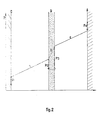
- the diaphragm in Figure 2 shows the distribution of potentials in the electrolysis cell during its operation.
- the potential (P) which exists in the electrolysis cell in operation in the interval between cathode and anode is represented on the ordinate, represented on the abscissa.
- Cathode C, diaphragm D and anode A are shown schematically.
- the straight sections a, b and c respectively represent the potential variations which occur in the catholyte, in the electrolyte which impregnates the diaphragm and in the anolyte.
- the vertical vectors P i , P 2 . P 3 and P 4 respectively represent the potential differences between the cathode, the cathode and anode faces of the diaphragm and the anode with respect to the electrolyte in contact.
- the variation of the potential “b” is equal to the product of 1 (electrolysis current) by R D (resistance of the electrolyte which permeates the diaphragm).
- 1 x R D varies in the opposite direction to the permeability.
- the equilibrium potential of the diaphragm P 3 with respect to the anolyte is defined by the formula:
- the conventions are the same as in the previous one and “a Ti2- anodic represents the activity of Ti2 + ions in the anolyte.
- IR D is therefore a measure of the efficiency of the diaphragm as a means of preventing the diffusion of titanium ions towards the anolyte.
- the diaphragm becomes bipolar and an alkali or alkaline earth deposit appears on the face of the diaphragm opposite the anode.
- the current yield on the anode side then collapses quickly by recombination of the chlorine released at the anode with the alkalis formed.
- chlorine ions are discharged which cause a rapid attack on this diaphragm.
- too high permeability of the diaphragm is undesirable since the diffusion of Ti ions from the catholyte to the anolyte in too large a quantity would lead to too great a reduction in yield.
- the method for controlling the permeability of the diaphragm according to the invention consists in controlling the deposition of titanium which takes place there more or less naturally either with a view to increasing it, or with a view to partially redissolving it, this growth or this redissolution being subject to the variation of the voltage drop across the electrolyte which permeates the diaphragm. It is thus possible, in an extremely simple manner, to choose in advance, according to the characteristics of the cell, a special value of this drop in potential and to keep it within a determined range.
- the potential drop across the diaphragm should be kept below a upper limit, of the order of a volt, which corresponds to the difference between the deposition potential of Ti2 + and that of the alkali or alkaline earth metal.
- a upper limit of the order of a volt, which corresponds to the difference between the deposition potential of Ti2 + and that of the alkali or alkaline earth metal.
- this difference should not exceed the value which corresponds to the discharge of alkaline ions on the diaphragm.
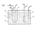
- a particularly advantageous device represented in FIG. 3 consists in connecting the diaphragm to a current source capable of ensuring the passage of this current in both directions, the other pole of this source being connected to the cathode.
- FIG. 3 schematically represents an electrolysis cell whose design derives from that of the cell in FIG. 1.
- the metal electrolysis cell (10) contains the electrolyte (11) whose composition is similar to that described above for the preparation of titanium.
- the anode (12) is surrounded by a diaphragm (15).
- the anode is connected, as usual, to the positive pole of a first current source not shown, whose negative pole is connected to the cathodes.
- the diaphragm is connected either to the positive pole or to the negative pole of a second source of current not shown, the other pole of which is connected to the cathode, and which is capable of ensuring the passage through this diaphragm of a current 1 3 in the desired direction.
- the TiCI 4 supply cathode (14) and the deposition cathode (15) are similar to those already described in FIG. 1.
- a device known to a person skilled in the art enables the direction and intensity 1 3 of the current injected into the diaphragm to be controlled by the variation in the voltage drop IR D , through the electrolyte permeating that this, which is detected by one of the means described above and, for example, by the continuous measurement of the potential difference between the diaphragm and the anode.
- the injection of current 1 3 through the diaphragm is started as soon as the voltage drop across the electrolyte permeating it deviates in one direction or the other from the reference voltage.
- the servo-control makes it possible to inject a current 1 3 in the desired direction the more intense the greater the difference between the voltage drop across the electrolyte impregnating the diaphragm and the reference voltage.
- the process is self-regulating, that is to say so that the increase in the intensity of the current as a function of the voltage difference is greater than the value strictly necessary, in order to accelerate the deposit or dissolution and thus promote, as far as possible, a return to normal conditions of permeability of the diaphragm.
- the means for controlling the permeability of the diaphragm according to the invention which has just been described, can be applied not only to the case of titanium, but also to that of the preparation by electrolysis of other polyvalent metals such as zirconium. , hafnium, vanadium, niobium or tantalum.
Landscapes
- Chemical & Material Sciences (AREA)
- Organic Chemistry (AREA)
- Chemical Kinetics & Catalysis (AREA)
- Electrochemistry (AREA)
- Materials Engineering (AREA)
- Metallurgy (AREA)
- Engineering & Computer Science (AREA)
- Electrolytic Production Of Metals (AREA)
- Professional, Industrial, Or Sporting Protective Garments (AREA)
- Secondary Cells (AREA)
- Apparatus Associated With Microorganisms And Enzymes (AREA)
- Manufacture And Refinement Of Metals (AREA)
- Electrodes For Compound Or Non-Metal Manufacture (AREA)
- Separation Using Semi-Permeable Membranes (AREA)
Claims (3)
Priority Applications (1)
| Application Number | Priority Date | Filing Date | Title |
|---|---|---|---|
| AT81420172T ATE20481T1 (de) | 1980-11-27 | 1981-11-25 | Verfahren zum ueberwachen der diaphragmadurchlaessigkeit waehrend der elektrolytischen vorbereitung mehrwertiger metalle und elektrolysezelle zur durchfuehrung dieses verfahrens. |
Applications Claiming Priority (2)
| Application Number | Priority Date | Filing Date | Title |
|---|---|---|---|
| FR8025504 | 1980-11-27 | ||
| FR8025504A FR2494728A1 (fr) | 1980-11-27 | 1980-11-27 | Procede de controle de la permeabilite des diaphragmes dans la preparation de metaux polyvalents par electrolyse et cellule d'electrolyse pour la mise en oeuvre de ce procede |
Publications (2)
| Publication Number | Publication Date |
|---|---|
| EP0053564A1 EP0053564A1 (de) | 1982-06-09 |
| EP0053564B1 true EP0053564B1 (de) | 1986-06-18 |
Family
ID=9248544
Family Applications (1)
| Application Number | Title | Priority Date | Filing Date |
|---|---|---|---|
| EP81420172A Expired EP0053564B1 (de) | 1980-11-27 | 1981-11-25 | Verfahren zum Überwachen der Diaphragmadurchlässigkeit während der elektrolytischen Vorbereitung mehrwertiger Metalle und Elektrolysezelle zur Durchführung dieses Verfahrens |
Country Status (7)
| Country | Link |
|---|---|
| US (1) | US4392924A (de) |
| EP (1) | EP0053564B1 (de) |
| JP (1) | JPS5834552B2 (de) |
| AT (1) | ATE20481T1 (de) |
| DE (1) | DE3174851D1 (de) |
| FR (1) | FR2494728A1 (de) |
| NO (1) | NO155703C (de) |
Families Citing this family (5)
| Publication number | Priority date | Publication date | Assignee | Title |
|---|---|---|---|---|
| FR2560896B1 (fr) * | 1984-03-12 | 1989-10-20 | Pechiney | Procede d'obtention d'un metal par electrolyse d'halogenures en bain de sels fondus comportant un double depot simultane et continu et dispositifs d'application |
| US4686025A (en) * | 1984-03-12 | 1987-08-11 | Pechiney | Apparatus for the production of a metal by electrolyzing halides in a molten salt bath, by a simultaneous continuous double deposit |
| ES8609513A1 (es) * | 1985-06-21 | 1986-09-01 | Hermana Tezanos Enrique | Nuevo diseno de catodo para beneficio electroquimico de me- tales |
| AU6870591A (en) * | 1989-06-30 | 1991-03-11 | Glen J. Schoessow | Electrochemical nuclear process and apparatus for producing tritium, heat, and radiation |
| JP5504515B2 (ja) * | 2008-05-01 | 2014-05-28 | 独立行政法人産業技術総合研究所 | 希土類金属の回収方法 |
Citations (1)
| Publication number | Priority date | Publication date | Assignee | Title |
|---|---|---|---|---|
| US2789943A (en) * | 1955-05-05 | 1957-04-23 | New Jersey Zinc Co | Production of titanium |
Family Cites Families (4)
| Publication number | Priority date | Publication date | Assignee | Title |
|---|---|---|---|---|
| FR1149544A (fr) * | 1955-05-05 | 1957-12-27 | New Jersey Zinc Co | Production de titane |
| FR2405311A1 (fr) * | 1977-10-10 | 1979-05-04 | Sred Az I Tsvetnoi | Procede de controle et d'optimalisation automatiques du regime de depot electrolytique d'un metal et dispositif pour sa mise en oeuvre |
| FR2423555A1 (fr) * | 1978-04-21 | 1979-11-16 | Dow Chemical Co | Appareil et procede pour l'obtention par electrolyse de metaux polyvalents |
| JPS5914556B2 (ja) * | 1978-04-28 | 1984-04-05 | ザ ダウ ケミカル カンパニ− | チタン電解製造用金属性隔膜および該隔膜を使用する電解槽と該電解槽中でのチタン製造法 |
-
1980
- 1980-11-27 FR FR8025504A patent/FR2494728A1/fr active Granted
-
1981
- 1981-10-20 US US06/313,229 patent/US4392924A/en not_active Expired - Lifetime
- 1981-11-25 JP JP56189034A patent/JPS5834552B2/ja not_active Expired
- 1981-11-25 DE DE8181420172T patent/DE3174851D1/de not_active Expired
- 1981-11-25 EP EP81420172A patent/EP0053564B1/de not_active Expired
- 1981-11-25 AT AT81420172T patent/ATE20481T1/de not_active IP Right Cessation
- 1981-11-26 NO NO814028A patent/NO155703C/no unknown
Patent Citations (1)
| Publication number | Priority date | Publication date | Assignee | Title |
|---|---|---|---|---|
| US2789943A (en) * | 1955-05-05 | 1957-04-23 | New Jersey Zinc Co | Production of titanium |
Also Published As
| Publication number | Publication date |
|---|---|
| JPS5834552B2 (ja) | 1983-07-27 |
| US4392924A (en) | 1983-07-12 |
| NO814028L (no) | 1982-05-28 |
| JPS57116789A (en) | 1982-07-20 |
| NO155703C (no) | 1987-05-13 |
| EP0053564A1 (de) | 1982-06-09 |
| FR2494728B1 (de) | 1984-03-02 |
| FR2494728A1 (fr) | 1982-05-28 |
| ATE20481T1 (de) | 1986-07-15 |
| DE3174851D1 (en) | 1986-07-24 |
| NO155703B (no) | 1987-02-02 |
Similar Documents
| Publication | Publication Date | Title |
|---|---|---|
| EP0037325B1 (de) | Elektrolytisches Verfahren unter Verwendung poröser Elektroden und dessen Anwendung zur Metallgewinnung aus wässrigen Lösungen | |
| EP0113931B1 (de) | Kathode zur elektrolytischen Herstellung von Wasserstoff und ihre Anwendung | |
| EP0556112B1 (de) | Iontophoreseeinrichtung zur transdermalen Verabreichung einer vorgegebenen Gesamtmenge von aktiven Grundstoffen an ein Lebewesen | |
| EP0053564B1 (de) | Verfahren zum Überwachen der Diaphragmadurchlässigkeit während der elektrolytischen Vorbereitung mehrwertiger Metalle und Elektrolysezelle zur Durchführung dieses Verfahrens | |
| CA2208913C (fr) | Procede de regulation de la teneur en alumine du bain des cuves d'electrolyse pour la production d'aluminium | |
| EP0038244B1 (de) | Verfahren zur Ablagerung auf leitungsfähigen Oberflächen, insbesondere auf Metalloberflächen, dünner organischer Filme durch Elektropolymerisierung und so erhaltene dünne Filme | |
| FR2643653A1 (fr) | Diaphragme pour electrolyse en bain de sels fondus d'halogenures de metaux | |
| EP0053565B1 (de) | Vorrichtung und Verfahren zur Zufuhr von TiCl4 in Elektrolysezellen für die Titanherstellung | |
| FR2723107A1 (fr) | Procede de reduction electrolytique d'un disulfure et produit ainsi obtenu | |
| FR2462489A1 (fr) | Procede de preparation d'electrodes a faible surtension d'hydrogene, electrodes ainsi formees et application a l'electrolyse des solutions aqueuses de chlorures alcalins | |
| US4416746A (en) | Bipolar refining of lead | |
| EP3555345B1 (de) | Elektrolytisches verfahren zur extraktion von zinn oder gleichzeitig zinn und blei enthalten in einem elektrisch leitenden gemisch | |
| EP0061392A1 (de) | Verfahren und Vorrichtung zur Elektrobehandlung von gemischten pulverigen Stoffen | |
| FR2680523A1 (fr) | Procede d'electrodeposition. | |
| EP1838903B1 (de) | Verfahren zur galvanischen abscheidung eines metalls zur herstellung von zellen mit elektroden-polymerfestelektrolyt | |
| EP0410919A1 (de) | Verfahren zur Elektroplattierung einer Metalloberfläche und Elektrolysezelle zur Durchführung des Verfahrens | |
| EP0197867B1 (de) | Verfahren zur Erhöhung der Reinheit von Übergangsmetallen, die durch Elektrolyse aus ihren geschmolzenen Halogeniden gewonnen werden | |
| EP0527882B1 (de) | Vorrichtung und verfahren für die elektrolyse mit poröser elektrode | |
| EP2173928A1 (de) | Anlage und verfahren zur elektrolytischen verzinnung von stahlstreifen mithilfe einer nichtlöslichen anode | |
| EP0321536B1 (de) | Verfahren zur anodischen passivierung von kupfer in einer umgebung von geschmolzenen fluoriden, anwendung zum schutz von kupferteilen von fluor-elektrolyseanlagen | |
| FR2544751A1 (fr) | Elimination de l'argent de melanges de chlorure complexes d'argent et de cuivre | |
| FR3128456A1 (fr) | Procédé de production d’hydrogène sous pression par électrolyse de l’eau découplée | |
| BE882550R (fr) | Procede de formation d'hydrogene | |
| BE481455A (de) | ||
| BE521185A (de) |
Legal Events
| Date | Code | Title | Description |
|---|---|---|---|
| PUAI | Public reference made under article 153(3) epc to a published international application that has entered the european phase |
Free format text: ORIGINAL CODE: 0009012 |
|
| AK | Designated contracting states |
Designated state(s): AT DE GB IT SE |
|
| 17P | Request for examination filed |
Effective date: 19820622 |
|
| RAP1 | Party data changed (applicant data changed or rights of an application transferred) |
Owner name: PECHINEY |
|
| GRAA | (expected) grant |
Free format text: ORIGINAL CODE: 0009210 |
|
| AK | Designated contracting states |
Kind code of ref document: B1 Designated state(s): AT DE GB IT SE |
|
| REF | Corresponds to: |
Ref document number: 20481 Country of ref document: AT Date of ref document: 19860715 Kind code of ref document: T |
|
| ITF | It: translation for a ep patent filed | ||
| REF | Corresponds to: |
Ref document number: 3174851 Country of ref document: DE Date of ref document: 19860724 |
|
| PLBE | No opposition filed within time limit |
Free format text: ORIGINAL CODE: 0009261 |
|
| STAA | Information on the status of an ep patent application or granted ep patent |
Free format text: STATUS: NO OPPOSITION FILED WITHIN TIME LIMIT |
|
| 26N | No opposition filed | ||
| PGFP | Annual fee paid to national office [announced via postgrant information from national office to epo] |
Ref country code: SE Payment date: 19911023 Year of fee payment: 11 |
|
| PG25 | Lapsed in a contracting state [announced via postgrant information from national office to epo] |
Ref country code: SE Effective date: 19921126 |
|
| ITTA | It: last paid annual fee | ||
| EUG | Se: european patent has lapsed |
Ref document number: 81420172.9 Effective date: 19930610 |
|
| PGFP | Annual fee paid to national office [announced via postgrant information from national office to epo] |
Ref country code: GB Payment date: 19961014 Year of fee payment: 16 |
|
| PGFP | Annual fee paid to national office [announced via postgrant information from national office to epo] |
Ref country code: DE Payment date: 19961019 Year of fee payment: 16 |
|
| PGFP | Annual fee paid to national office [announced via postgrant information from national office to epo] |
Ref country code: AT Payment date: 19961023 Year of fee payment: 16 |
|
| PG25 | Lapsed in a contracting state [announced via postgrant information from national office to epo] |
Ref country code: GB Free format text: LAPSE BECAUSE OF NON-PAYMENT OF DUE FEES Effective date: 19971125 Ref country code: AT Free format text: LAPSE BECAUSE OF NON-PAYMENT OF DUE FEES Effective date: 19971125 |
|
| GBPC | Gb: european patent ceased through non-payment of renewal fee |
Effective date: 19971125 |
|
| PG25 | Lapsed in a contracting state [announced via postgrant information from national office to epo] |
Ref country code: DE Free format text: LAPSE BECAUSE OF NON-PAYMENT OF DUE FEES Effective date: 19980801 |