EP0053510A2 - Strangpressverfahren - Google Patents
Strangpressverfahren Download PDFInfo
- Publication number
- EP0053510A2 EP0053510A2 EP81305652A EP81305652A EP0053510A2 EP 0053510 A2 EP0053510 A2 EP 0053510A2 EP 81305652 A EP81305652 A EP 81305652A EP 81305652 A EP81305652 A EP 81305652A EP 0053510 A2 EP0053510 A2 EP 0053510A2
- Authority
- EP
- European Patent Office
- Prior art keywords
- extruded
- combustion improver
- extrusion
- billet
- mandrel
- Prior art date
- Legal status (The legal status is an assumption and is not a legal conclusion. Google has not performed a legal analysis and makes no representation as to the accuracy of the status listed.)
- Granted
Links
Images


Classifications
-
- B—PERFORMING OPERATIONS; TRANSPORTING
- B21—MECHANICAL METAL-WORKING WITHOUT ESSENTIALLY REMOVING MATERIAL; PUNCHING METAL
- B21C—MANUFACTURE OF METAL SHEETS, WIRE, RODS, TUBES, PROFILES OR LIKE SEMI-MANUFACTURED PRODUCTS OTHERWISE THAN BY ROLLING; AUXILIARY OPERATIONS USED IN CONNECTION WITH METAL-WORKING WITHOUT ESSENTIALLY REMOVING MATERIAL
- B21C23/00—Extruding metal; Impact extrusion
- B21C23/007—Hydrostatic extrusion
-
- B—PERFORMING OPERATIONS; TRANSPORTING
- B21—MECHANICAL METAL-WORKING WITHOUT ESSENTIALLY REMOVING MATERIAL; PUNCHING METAL
- B21C—MANUFACTURE OF METAL SHEETS, WIRE, RODS, TUBES, PROFILES OR LIKE SEMI-MANUFACTURED PRODUCTS OTHERWISE THAN BY ROLLING; AUXILIARY OPERATIONS USED IN CONNECTION WITH METAL-WORKING WITHOUT ESSENTIALLY REMOVING MATERIAL
- B21C23/00—Extruding metal; Impact extrusion
- B21C23/32—Lubrication of metal being extruded or of dies, or the like, e.g. physical state of lubricant, location where lubricant is applied
-
- B—PERFORMING OPERATIONS; TRANSPORTING
- B21—MECHANICAL METAL-WORKING WITHOUT ESSENTIALLY REMOVING MATERIAL; PUNCHING METAL
- B21C—MANUFACTURE OF METAL SHEETS, WIRE, RODS, TUBES, PROFILES OR LIKE SEMI-MANUFACTURED PRODUCTS OTHERWISE THAN BY ROLLING; AUXILIARY OPERATIONS USED IN CONNECTION WITH METAL-WORKING WITHOUT ESSENTIALLY REMOVING MATERIAL
- B21C43/00—Devices for cleaning metal products combined with or specially adapted for use with machines or apparatus provided for in this subclass
Definitions
- This invention relates to a method for extruding solid or tubular products using a lubricant, including. removing the deposit of carbonized lubricant produced on the surface of each extruded product thereby to improve the quality of the extruded products and facilitate their aftertreatment.
- non-lubricated extrusion which is widely used for non-ferrous materials (e.g., aluminium and copper alloys)
- extrusion with a glass lubricant and extrusion with a carbon-base lubricant which are used mainly for steel materials
- hydrostatic extrusion which is applicable to a wide variety of metallic materials.
- a lubricated extruding process in which a billet precoated with a carbon-base lubricant is loaded into a container after heating and extruded through a die and/or a mandrel or in which the container as well as the die and/or mandrel is coated with a carbonbase lubricant prior to loading a heated billet in to the container for extrusion and the hydrostatic extrusion process in which a hot billet loaded in a container is extruded by the pressure medium applied to the surface of the billet (with the forced lubricating effect of the pressure medium) each have a common problem in that the surfaces of the extruded tubular product are darkened due to depositions of a carbide formed from the used lubricant, which is formed by the extrusion at a high temperature.
- the carbide deposit on the extruded product not only lowers its value but-also can cause corrosion when the tubular product is used as a condensor tube of a heat exchanger or the like.
- the deposit of carbonized lubricant gives rise to a similar problem even when an iron-base material is extruded with the use of a carbon-base lubricant.
- the present invention provides a method of hot lubricated metal extrusion in which a billet is extruded by means of a die and/or mandrel with an organic lubricant interposed between said billet and die and/or mandrel, said method comprising feeding a combustion improver or a mixture of a combustion improver and water to a surface of the extruded product to burn off the carbide of said lubricant deposited on the surface of said extruded product.
- the billet is extruded into a tubular form by means of a die and a mandrel, said method further . comprising feeding the combustion improver or a mixture of the combustion improver and water into the extruded tubular product through a feed passage in said mandrel to burn off the carbide of said lubricant deposited on the inner surface, of said extruded tubular product.
- said combustion improver may be air and is preferably fed at a rate of Q falling in the range of 1.8d.R.V ⁇ Q ⁇ 14.2d.R.V (where d is the inner diameter of the product in cm, R is the extrustion ratio, and V is the billet extruding speed in cm/sec.)
- combustion improver is fed to an outer surface of the extruded material at a combustion improver feed zone located downstream of an extrusion die to burn off the carbide of said lubricant deposited on the outer surface of said extruded material, and water is fed to the outer surface of the extruded material at a water cooling zone to prevent oxidation on the outer surface and suppress grain growth of said extruded material.
- the feeding rate of the air is controlled to satisfy the following condition; 0.3D ⁇ R ⁇ v ⁇ Q ⁇ 0.7D ⁇ R ⁇ v wherein Q is rate of feed of air (1/min), D is the outer diameter of extruded material (cm), R is the extrusion ratio, and v is the extrusion speed (stem speed) (cm/sec).
- the invention also provides an extrusion apparatus for hot lubricated metal extrusion comprising a die and/or mandrel, a container into which a billet to be extruded, in use, is loaded with an organic lubricant interposed between said billet and die and/or mandrel, and means for feeding a combustion improver or a mixture of a combustion improver and water to a surface of the extruded-product to burn off the carbide of said lubricant deposited on the surface of said extruded product.
- said mandrel may include a feed passage to feed said combustion improver or a mixture of combustion improver and water into the extruded tubular product to burn off the carbide of said lubricant deposited on the inner surfaces of said extruded tubular product.
- Said feeding means may be adapted to feed the combustion improver to the outer surface of the extruded material at a combustion improver feed zone located downstream of the extrusion die to burn off the carbide of said lubricant deposited on the outer surface of said extruded material, and water feed means may be provided to feed water to the outer surface of the extruded material at a water cooling zone located downstream of said combustion improver feed zone to prevent oxidation of the outer surface and to suppress grain growth of said extruded material.
- the invention also provides an extruded product manufactured by any of the above methods of the invention.
- FIGURES 1 and 2 illustrate a conventional hydrostatic extrusion and a similar hydrostatic extrusion incorporating the method of the present inverition. respectively.
- a hot hollow billet 3 which is heated to a high temperature of 500 0 C or more is loaded into a container 1 and a pressure medium 4 such as a commercially available non-soap type grease, liquid polymer or the like is spread on a mandrel 6 which projects from the front end of a press stem 7 through a seal piston 5, a pressure medium 4 surrounding hollow billet 3 which is extruded by displacement of the stem 7 into a tubular product 3a through a space defined between the mandrel 6 and a press die 2, as shown in FIGURE 1.
- a pressure medium 4 such as a commercially available non-soap type grease, liquid polymer or the like
- the pressure medium 4 sticks to the extruded billet and forms carbide deposits on the inner and outer surfaces of the tubular product 3a which is extruded at a high temperature.
- the hollow billet 3 is precoated with a carbon-base lubricant and heated before charging into the container 1, and then extruded into a tubular form 3a through the mandrel 6 and die 2.
- a heated hollow billet 3 is charged into the container 1 after precoating the container 1, mandrel 6 and die 2 with carbon-base lubricant and similarly extruded into a tubular form 3a through the mandrel 6 and die 2.
- carbide of the lubricant is deposited onto the surfaces of the extruded tubular product in a manner similar to the hydrostatic extrusion.
- the carbonized lubricant or pressure medium deposit lowers the quality of the product and will cause corrosive degradation. Thus as mentioned before the deposit should be removed completely.
- the present invention succeeded in completely burning off the lubricant-and pressure medium which is extruded along with the tubular product through the gap between the mandrel 6 and billet 3, by injecting a combustion improver or a mixture of a combustion improver and water into the tubular product being extruded.
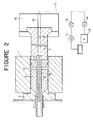
- FIGURE 2 depicts a hot lubricated extrusion incorporating the method of the present invention, in which a container 1, die 2, hollow billet 3, pressure medium 4, seal piston 5, mandrel 6 and stem 7 are arranged substantially in the same manner as in FIGURE 1.
- an axial bore 8 is provided centrally through the mandrel 6 to feed a combustion improver or a mixture of a combustion improver and water as shown in FIGURE 2.
- bores 9 and 16 are provided through the stem 7 in communication with the bore 8.
- the stem 7 holds the mandrel 6 and is held in a crosshead 16 which is movable back and forth together with the stem 7.
- air is referred to as an example of a combustion improver which is fed to a supply passage 17 alone through a valve 14 or together with water which is fed from a pump 11 through a valve 12.
- combustion improver in the present invention, it is preferred to employ a combustion improver in the form of a gas in view of the ease of control of the feeding of the improver continuously from outside into the extruded tubular product through the axial through bores in the mandrel 6 and stem 7 or other components of the press. It is particularly preferred to use atmospheric air which is easily available and advantageous from the standpoint of cost and safety.
- combustion improver alone can attain the purpose of the present invention
- its combined use with water serves to cool the mandrel by forming a mist when the combustion improver is in the form of a gas like air.
- the combustion improver is fed in a mist form to cool off the tube, the carbide deposits on the inner surface of the tubular product are burned off immediately upon extrusion thereof so that the temperature drop of the tube does not hinder the removal of the carbide.
- the required air in compressed form is fed from an air compressor 13 into the extruded tube through the air supply passage 17 and axial bores 16, 9 and 8.
- the air is slightly heated during its passage through the mandrel 6, by absorbing heat from the latter, to a level higher than 50°C, while the hollow billet 3 is heated to 500 to 1150 0 C prior to loading it into the container 1 and extruding it at a stem speed of 40 to 50 mm/sec.
- the air which is supplied in this manner reacts with the lubricant or pressure medium 4 which is extruded with the tubular product 3a through the gap between the mandrel 6 and billet 3, to completely burn off the lubricant or pressure medium by virtue of the heat of the extruded tubular product 3. If the tubular product is extruded at a low temperature, it is necessary to select a suitable lubricant or pressure medium which will be burnt off at the lower temperature.
- a billet heated similarly to a temperature above 500°C may be charged into the container and extruded by means of a commercially available pressure medium such as a non-soap type grease containing an inorganic compound as a tackifier in a mineral oil or a viscous liquid polymer.
- a commercially available pressure medium such as a non-soap type grease containing an inorganic compound as a tackifier in a mineral oil or a viscous liquid polymer.
- a viscous liquid polymer it is preferred to employ a viscous liquid polymer as a pressure medium for hydrostatic extrusion.
- the complete burn-off of the lubricant or pressure medium by air or another combustion improver which is fed into the extuded tubular product through the axial bore 8 in the mandrel in accordance with the method of the present invention can be applied to billets in a very wide temperature range.
- the combustion improver is in the form of a gas like air as in the above-described embodiment, it should be fed at such a rate that the oxygen content in the gas is sufficient for completely burning off the lubricant or pressure medium which is extruded.along with the billet 3 through the gap between the mandrel 6 and billet 3.
- the extruded tubular product 3a may bear on its inner surface closely deposited amorphous carbon particles to a thickness of 0.3 to 0.5 microns. Therefore, it is sufficient to feed oxygen in sufficient quantity to completely burn off the 0.5 micron thick amorphous carbon deposit but desirably more than the minimum amount of oxygen should be supplied for reliable and stable operation.
- the combustion improver is used in a mist form
- water in a reservoir or tank 10 is fed by a pump 11 through a valve 12 as shown in FIGURE 2 and mixed under increased pressure with the compressed air from the air compressor 13, the mist being fed to the axial bore 8 of the mandrel 6 through the supply passage 17 and axial bores 16 and 9.
- the misty combustion improver gas is fed also into the tubular product being extruded as mentioned hereinbefore but its acceleration of the cooling effect on the extruded tube causes no problems since the carbide on the inner surfaces of the extrudate is burned off immediately upon extrustion by the die 2 and mandrel 6.
- the existence of a slight oxidation film or a thin drawable film of Cu 2 O is permissible, which however turns into CuO if oxygen is supplied in an excess amount.
- the production of the oxidation film of Cu0 causes deteriorations in the surface properties in the drawing stage, and it is difficult to remove it by reduction by bright annealing which is usually effected subsequent to the drawing. Therefore, the feed rate of the combustion improver should be so controlled as not to produce an oxidation film of CuO.
- the present invention has succeeded in establishing effective and reliable principles common to ferrous or non-ferrous metal billets, as a result of repeated experiments and studies. More particularly, the carbide (of the lubricant or pressure medium) which deposits on the inner surfaces of the tubular extrudate 3a through the gap between the mandrel 6 and billet 3 is complete burned off in the region to which the combustion improver such as oxygen and air is blown in from the inner end of the axial bore -8 of the mandrel 6.
- the combustion improver should not remain, even in a small amount in the tube after it has passed from the region where combustion takes place if a sound tubular product3a is to be manufactured in which the inner surfaces are completely free of combustible carbide and in which the base metal is not oxidised.
- the combustion improver still remains in the tube which has passed the combustion region and reacts with the base metal to form an objectionable oxidation film, the oxidation reaction terminating when the combustion improver becomes scarce because of the formation of the oxidation film.
- the feed rate Q of the combustion improver for good extrusion is commonly in the range defined below, which is effectively applicable no matter whether the billet is a non-ferrous metal like a cuprous metal or a ferrous metal like carbon steel (S45C) or the like. It has been experimentally confirmed that this method is effective especially for the extrusion of a billet of copper or a copper alloy using air as the combustion improver.
- the abovementioned suitable range of the combustion improver feed rate Q is where the feed rate Q is in the unit of 1/min.
- the feed of the combustion improver should be cut off when the extruding speed becomes zero upon completion of extrusion.of the tubular product 3a. If the feed is cut off with a time delay at the time of completion of extrusion localized oxidation takes place due to the presence of excess oxygen as mentioned before and the oxidized area extends toward the front end of the tubular product 3a. However, a slight time delay should desirably be allowed in the actual operation.
- the time point for stopping the feed of combustion improver if it is cut off before the extrusion: is complete, the combustion of the carbide in the extruded tubular product 3a becomes incomplete and deposits of combustible carbide appear at the rear end of the extruded product.
- the feed of the combustion improver is stopped after a delay, an oxidation film is formed at the rear end of the product to a conspicuous degree due to the supply of excess oxygen.
- the feed of the combustion improver should be controlled in a suitable time range which does not lower the production yield, and in actual operations should suitably be stopped within a time range from one second before to five seconds after the termination of the extrusion of the tubular product 3a.
- the billet may be extruded under a condition in which a slight oxidation film is formed on the inner surface of the extruded tube by residual oxygen, and reducing the oxidation film by feeding through the mandrel 6 a DX gas (2.85%CO, 1.99%H, 11.9%CO and the balance.of N) in the succeeding cooling phase of the tubular product 3a. Since the DX gas is fed after termination of the extrusion, it is necessary to maintain the tubular product 3a in a temperature range suitable for the reduction reaction.
- the residual gas in the extruded tube may be replaced by a non-oxidative gas such as an inert gas or reduction gas to improve the quality of the product.
- Tables 1 to 3 illustrate the results of more specific extrusion experiments according to the method of the present invention in comparison with corresponding conventional methods.
- the subject of the experiment is captioned on each table.
- deposited carbonized lubricant on the outer surface of extruded material can also be removed by feeding combustion improver to the outer surface of the extruded material which leaves the extrustion die, and bringing coolant liquid into contact with the outer surface of the material after the carbonized lubricant is burned off.
- carbonized lubricant remaining on the outer surface can be completely removed, oxidation film formation can be prevented, and crystal grain growth of the extruded product can also be suppressed.
- the thickness of the carbonized lubricant retained on the outer surface of the extruded tube is at most 1.4 ⁇ m.
- the optimum amount of combustion improver is fed to the extruded material while the material is still hot. If the amount of combustion improver is insufficient, carbide will remain on the outer surface, but if the amount of combustion improver is too much, an oxidized film is formed on the outer surface of the extruded material.
- FIGURE 3 is a diagram of an apparatus for carrying out the method of the invention.
- An air feeding zone A is provided downstream of the extrusion die 2 so that air is brought into contact with the outer circumference of the extruded material.
- a water cooling zone w is , provided downstream of said air feeding zone A, so as to prevent oxidation and to suppress cyrstal grain growth of the extruded material.
- the amount of air feed should be proportional to the surface area of the extruded material that passes through the combustion zone (air feeding zone) per unit time period. Therefore, the air feeding rate Q (1/m) can be obtained by the following formula; where K is a constant, D is the outer diameter of extruded material, (cm), R is the extrusion ration, and v is the extrusion speed (stem speed) (cm/sec).
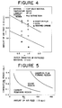
- FIGURE 4 is a graph showing the relationship between the surface quality of the extruded material and the extrusion conditions. More specifically there is shown a relationship between the amount of air feed (Q) and the outer diameter of the extruded material (D). As can be seen from this graph, an excess of air feed causes formation of an oxidation film on the outer surface of the extruded material. In order to completely remove the carbonized lubricant and to prevent the oxidation on the outer surface of the extruded material, the following condition should be satisfied:
- FIGURE 5 shows the relationship between the period of time for the material to pass through the air feeding zone and the amount of air fed.
- the desired period for the material to pass through the air feeding zone varies depending on the amount of air fed, but if the amount of air fed is 140 1/m, the period shall preferably be shorter than 0.13 second. If the amount of air fed is 70 1/min, the period should preferably be shorter than 0.35 second. Generally as the amount of air fed becomes less, the period should be longer, but then the extruded material will cool resulting in coarse grains within the extruded material.
- Crystal grains of extruded cupro-nickel tube do not grow even if the tube is slowly cooled in the atmosphere.
- aluminium brass crystal grains grow rapidly and the surface gets rough when it is drawn.
- the length of air feeding zone is considered for aluminium brass.
- the extrusion conditions are;
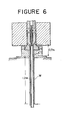
- FIGURE 6 The extrusion took place with an apparatus shown in FIGURE 6.
- a 0.7 m long air feeding zone A is provided at the outlet side of the extrusion die, and a 1.2 m long water cooling zone W is provided downstream of said air feeding zone.
- the amount of water.feed was varied from 0 to 36 1/min.
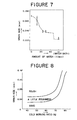
- the relationship between the amount of coolant water and the crystal grain size of the extruded aluminium brass is shown in FIGURE 7.
- mean grain size of the extruded tube was 0.07 mm.
- the grain size becomes smaller, and when the amount of water is 20 1/min, the grain size becomes finer than 0.04mm.
- the period of time for the material to pass through the air feeding zone is 0.41 second, which is a sufficient period for the carbonized lubricant to completely burn off judging from FIGURE 5.
- the outer surface of the extruded material can be cleared and grain growth can be suppressed by the provision of an air feeding zone which is followed by a water cooling zone at the downstream side of a hot hydrostatic extrusion die.
- the present invention is particularly excellent at completely removing the combustible carbide of the lubricant or pressure medium which tends to deposit on the surfaces of the solid or tubular product, permitting production of solid or tubular products with clean and defect-free surfaces in a simple manner.
- the combustion improver which may mainly consist of a combustion improver gas such as oxygen and air or a mixture of a combusion improver and water is fed to the initial billet extruding point of the die and/or mandrel to cause complete combustion of the combustible carbide under the high extruding temperature.
- the outer surface of the extruded material can by cleaned by removing carbonized lubricant by means of applying combustion improver. Oxidation and undesirable grain growth of the extruded material can be prevented by bringing coolant into direct contact with the outer surface.
Landscapes
- Engineering & Computer Science (AREA)
- Mechanical Engineering (AREA)
- Extrusion Of Metal (AREA)
Applications Claiming Priority (2)
| Application Number | Priority Date | Filing Date | Title |
|---|---|---|---|
| JP16991880A JPS5791822A (en) | 1980-11-29 | 1980-11-29 | High-temperature lubrication extrusion method for tubular product |
| JP169918/80 | 1980-11-29 |
Publications (3)
| Publication Number | Publication Date |
|---|---|
| EP0053510A2 true EP0053510A2 (de) | 1982-06-09 |
| EP0053510A3 EP0053510A3 (en) | 1982-07-14 |
| EP0053510B1 EP0053510B1 (de) | 1985-05-22 |
Family
ID=15895361
Family Applications (1)
| Application Number | Title | Priority Date | Filing Date |
|---|---|---|---|
| EP19810305652 Expired EP0053510B1 (de) | 1980-11-29 | 1981-11-30 | Strangpressverfahren |
Country Status (4)
| Country | Link |
|---|---|
| EP (1) | EP0053510B1 (de) |
| JP (1) | JPS5791822A (de) |
| CA (1) | CA1191480A (de) |
| DE (1) | DE3170645D1 (de) |
Cited By (4)
| Publication number | Priority date | Publication date | Assignee | Title |
|---|---|---|---|---|
| WO2002085560A1 (en) * | 2001-04-19 | 2002-10-31 | Alcoa Inc. | Injector for molten metal supply system |
| WO2003055626A1 (en) * | 2001-12-28 | 2003-07-10 | Bbs-Riva S.P.A. | Hydraulic device for pumping molten metal and/or controlling a molten metal flow |
| US7934627B2 (en) | 2005-10-13 | 2011-05-03 | Alcoa Inc. | Apparatus and method for high pressure extrusion with molten aluminum |
| CN114916223A (zh) * | 2020-12-08 | 2022-08-16 | 丸嘉工业株式会社 | 管材的制造方法 |
Families Citing this family (3)
| Publication number | Priority date | Publication date | Assignee | Title |
|---|---|---|---|---|
| JPS5919769B2 (ja) * | 1981-11-04 | 1984-05-08 | 昭和アルミニウム株式会社 | 真空用アルミニウム製中空押出形材の製造法 |
| US6505674B1 (en) | 2001-04-19 | 2003-01-14 | Alcoa Inc. | Injector for molten metal supply system |
| EP1714718B1 (de) | 2001-04-19 | 2008-07-09 | Alcoa Inc. | Vorrichtung und Verfahren zur kontinuierlichen Metallschmelzezuführung unter Druck |
Family Cites Families (3)
| Publication number | Priority date | Publication date | Assignee | Title |
|---|---|---|---|---|
| DE1182193B (de) * | 1960-04-07 | 1964-11-26 | Hydraulik Gmbh | Kuehlvorrichtung an Metallrohrpressen |
| DE1602309A1 (de) * | 1967-05-12 | 1970-04-23 | Mannesmann Ag | Verfahren und Vorrichtung zum Entfernen von Schmiermittelbelaegen von den Oberflaechen stranggepresster Gegenstaende |
| DE2739800A1 (de) * | 1977-09-03 | 1979-03-22 | Schloemann Siemag Ag | Verfahren und einrichtung zur herstellung von kupferrohren, insbesondere mittels indirekt-metallstrangpressen |
-
1980
- 1980-11-29 JP JP16991880A patent/JPS5791822A/ja active Granted
-
1981
- 1981-11-25 CA CA000390886A patent/CA1191480A/en not_active Expired
- 1981-11-30 DE DE8181305652T patent/DE3170645D1/de not_active Expired
- 1981-11-30 EP EP19810305652 patent/EP0053510B1/de not_active Expired
Cited By (5)
| Publication number | Priority date | Publication date | Assignee | Title |
|---|---|---|---|---|
| WO2002085560A1 (en) * | 2001-04-19 | 2002-10-31 | Alcoa Inc. | Injector for molten metal supply system |
| WO2003055626A1 (en) * | 2001-12-28 | 2003-07-10 | Bbs-Riva S.P.A. | Hydraulic device for pumping molten metal and/or controlling a molten metal flow |
| US7427190B2 (en) | 2001-12-28 | 2008-09-23 | Bbs-Riva S.P.A. | Hydraulic device for pumping molten metal and/or controlling a molten metal flow |
| US7934627B2 (en) | 2005-10-13 | 2011-05-03 | Alcoa Inc. | Apparatus and method for high pressure extrusion with molten aluminum |
| CN114916223A (zh) * | 2020-12-08 | 2022-08-16 | 丸嘉工业株式会社 | 管材的制造方法 |
Also Published As
| Publication number | Publication date |
|---|---|
| CA1191480A (en) | 1985-08-06 |
| EP0053510B1 (de) | 1985-05-22 |
| DE3170645D1 (en) | 1985-06-27 |
| EP0053510A3 (en) | 1982-07-14 |
| JPS5791822A (en) | 1982-06-08 |
| JPS6144563B2 (de) | 1986-10-03 |
Similar Documents
| Publication | Publication Date | Title |
|---|---|---|
| EP0042814B1 (de) | Schnellstrangpressen warmbruch-empfindlicher Legierungen | |
| US4445350A (en) | Extrusion method using hot lubricant | |
| EP0053510B1 (de) | Strangpressverfahren | |
| JPS60114508A (ja) | 球状金属粒の製造方法 | |
| US4365995A (en) | Method of producing multi-layer sliding material | |
| US2974790A (en) | Cross-extrusion process | |
| US3088195A (en) | Cladding with powdered metal to form bimetallic products | |
| US3485753A (en) | Hot extrusion of metals and lubricant therefor | |
| US3135623A (en) | Surface treatment of steel billets to be extruded, and of extrusion tools | |
| PL101948B1 (pl) | A lubricant for hot-forming of metals | |
| US3350907A (en) | Method for extruding molybdenum and tungsten | |
| US4030328A (en) | Device for continuous lubrication of an extrusion die | |
| US3172536A (en) | Extrusion of metals of hollow section | |
| US2773593A (en) | Methods of extruding high copper alloys | |
| JPH0141408B2 (de) | ||
| JPS58128294A (ja) | 溶接用細径鋼ワイヤ | |
| JPS594204B2 (ja) | MgおよびCuを合金元素として含むアルミニウム合金の高温静水圧押出し方法 | |
| JPS60108497A (ja) | 継目無鋼管製造用固体潤滑剤 | |
| DE102018117405A1 (de) | Verfahren zum Entzundern eines Kupferausgangsmaterials für ein Fertigen eines Kupferproduktes und Kupferprodukt | |
| US3208262A (en) | Extrusion of ferrous metals through dies of metal silicides | |
| SU1724401A1 (ru) | Способ холодной прокатки труб | |
| SU1031541A1 (ru) | Способ винтовой прошивки | |
| Nishihara et al. | Hot hydrostatic extrusion of steel | |
| Edgecombe | Extrusion of steel | |
| Magie | MOLYBDENUM DISULPHIDE: as an Additive to Wire Drawing Compounds |
Legal Events
| Date | Code | Title | Description |
|---|---|---|---|
| PUAI | Public reference made under article 153(3) epc to a published international application that has entered the european phase |
Free format text: ORIGINAL CODE: 0009012 |
|
| PUAL | Search report despatched |
Free format text: ORIGINAL CODE: 0009013 |
|
| 17P | Request for examination filed |
Effective date: 19811208 |
|
| AK | Designated contracting states |
Designated state(s): DE FR GB |
|
| AK | Designated contracting states |
Designated state(s): DE FR GB |
|
| GRAA | (expected) grant |
Free format text: ORIGINAL CODE: 0009210 |
|
| AK | Designated contracting states |
Designated state(s): DE FR GB |
|
| REF | Corresponds to: |
Ref document number: 3170645 Country of ref document: DE Date of ref document: 19850627 |
|
| ET | Fr: translation filed | ||
| PLBE | No opposition filed within time limit |
Free format text: ORIGINAL CODE: 0009261 |
|
| STAA | Information on the status of an ep patent application or granted ep patent |
Free format text: STATUS: NO OPPOSITION FILED WITHIN TIME LIMIT |
|
| 26N | No opposition filed | ||
| PG25 | Lapsed in a contracting state [announced via postgrant information from national office to epo] |
Ref country code: FR Effective date: 19900731 |
|
| REG | Reference to a national code |
Ref country code: FR Ref legal event code: ST |
|
| PGFP | Annual fee paid to national office [announced via postgrant information from national office to epo] |
Ref country code: GB Payment date: 19911120 Year of fee payment: 11 |
|
| PGFP | Annual fee paid to national office [announced via postgrant information from national office to epo] |
Ref country code: DE Payment date: 19911230 Year of fee payment: 11 |
|
| PG25 | Lapsed in a contracting state [announced via postgrant information from national office to epo] |
Ref country code: GB Effective date: 19921130 |
|
| GBPC | Gb: european patent ceased through non-payment of renewal fee |
Effective date: 19921130 |
|
| PG25 | Lapsed in a contracting state [announced via postgrant information from national office to epo] |
Ref country code: DE Effective date: 19930803 |