EP0053355B1 - Elément de nettoyage et installation de nettoyage mettant en oeuvre cet élément - Google Patents
Elément de nettoyage et installation de nettoyage mettant en oeuvre cet élément Download PDFInfo
- Publication number
- EP0053355B1 EP0053355B1 EP81109896A EP81109896A EP0053355B1 EP 0053355 B1 EP0053355 B1 EP 0053355B1 EP 81109896 A EP81109896 A EP 81109896A EP 81109896 A EP81109896 A EP 81109896A EP 0053355 B1 EP0053355 B1 EP 0053355B1
- Authority
- EP
- European Patent Office
- Prior art keywords
- cleaning
- grain
- fluid
- cleaning component
- installation
- Prior art date
- Legal status (The legal status is an assumption and is not a legal conclusion. Google has not performed a legal analysis and makes no representation as to the accuracy of the status listed.)
- Expired
Links
- 238000004140 cleaning Methods 0.000 title claims abstract description 55
- 238000009434 installation Methods 0.000 title description 19
- 239000012530 fluid Substances 0.000 claims abstract description 29
- 239000000203 mixture Substances 0.000 claims abstract description 6
- 239000000126 substance Substances 0.000 claims abstract description 6
- 208000004434 Calcinosis Diseases 0.000 claims abstract 2
- VYPSYNLAJGMNEJ-UHFFFAOYSA-N Silicium dioxide Chemical compound O=[Si]=O VYPSYNLAJGMNEJ-UHFFFAOYSA-N 0.000 claims description 9
- VTYYLEPIZMXCLO-UHFFFAOYSA-L Calcium carbonate Chemical compound [Ca+2].[O-]C([O-])=O VTYYLEPIZMXCLO-UHFFFAOYSA-L 0.000 claims description 6
- 239000002245 particle Substances 0.000 claims description 4
- 239000004743 Polypropylene Substances 0.000 claims description 3
- 229910000019 calcium carbonate Inorganic materials 0.000 claims description 3
- 229910052593 corundum Inorganic materials 0.000 claims description 3
- 239000010431 corundum Substances 0.000 claims description 3
- -1 polypropylene Polymers 0.000 claims description 3
- 229920001155 polypropylene Polymers 0.000 claims description 3
- 239000010453 quartz Substances 0.000 claims description 3
- 239000000377 silicon dioxide Substances 0.000 claims description 2
- 238000003860 storage Methods 0.000 description 7
- XLYOFNOQVPJJNP-UHFFFAOYSA-N water Substances O XLYOFNOQVPJJNP-UHFFFAOYSA-N 0.000 description 7
- 229910052500 inorganic mineral Inorganic materials 0.000 description 3
- 239000000463 material Substances 0.000 description 3
- 239000011707 mineral Substances 0.000 description 3
- 239000003082 abrasive agent Substances 0.000 description 2
- 238000005243 fluidization Methods 0.000 description 2
- 238000002347 injection Methods 0.000 description 2
- 239000007924 injection Substances 0.000 description 2
- 239000007788 liquid Substances 0.000 description 2
- 239000002699 waste material Substances 0.000 description 2
- ZAMOUSCENKQFHK-UHFFFAOYSA-N Chlorine atom Chemical compound [Cl] ZAMOUSCENKQFHK-UHFFFAOYSA-N 0.000 description 1
- 239000005909 Kieselgur Substances 0.000 description 1
- 238000005299 abrasion Methods 0.000 description 1
- 238000009825 accumulation Methods 0.000 description 1
- WYTGDNHDOZPMIW-RCBQFDQVSA-N alstonine Natural products C1=CC2=C3C=CC=CC3=NC2=C2N1C[C@H]1[C@H](C)OC=C(C(=O)OC)[C@H]1C2 WYTGDNHDOZPMIW-RCBQFDQVSA-N 0.000 description 1
- 239000003795 chemical substances by application Substances 0.000 description 1
- 239000000460 chlorine Substances 0.000 description 1
- 229910052801 chlorine Inorganic materials 0.000 description 1
- 239000012459 cleaning agent Substances 0.000 description 1
- 238000013329 compounding Methods 0.000 description 1
- 238000005260 corrosion Methods 0.000 description 1
- 230000007797 corrosion Effects 0.000 description 1
- 238000010908 decantation Methods 0.000 description 1
- 230000007547 defect Effects 0.000 description 1
- 238000005259 measurement Methods 0.000 description 1
- 229910052751 metal Inorganic materials 0.000 description 1
- 239000002184 metal Substances 0.000 description 1
- 238000000034 method Methods 0.000 description 1
- 230000000737 periodic effect Effects 0.000 description 1
- 239000004033 plastic Substances 0.000 description 1
- 239000000843 powder Substances 0.000 description 1
- 150000003839 salts Chemical class 0.000 description 1
- 239000004576 sand Substances 0.000 description 1
- 238000000926 separation method Methods 0.000 description 1
- 239000007787 solid Substances 0.000 description 1
- 239000000725 suspension Substances 0.000 description 1
- 229920002994 synthetic fiber Polymers 0.000 description 1
Images

Classifications
-
- B—PERFORMING OPERATIONS; TRANSPORTING
- B08—CLEANING
- B08B—CLEANING IN GENERAL; PREVENTION OF FOULING IN GENERAL
- B08B9/00—Cleaning hollow articles by methods or apparatus specially adapted thereto
- B08B9/02—Cleaning pipes or tubes or systems of pipes or tubes
- B08B9/027—Cleaning the internal surfaces; Removal of blockages
- B08B9/032—Cleaning the internal surfaces; Removal of blockages by the mechanical action of a moving fluid, e.g. by flushing
- B08B9/0321—Cleaning the internal surfaces; Removal of blockages by the mechanical action of a moving fluid, e.g. by flushing using pressurised, pulsating or purging fluid
- B08B9/0325—Control mechanisms therefor
-
- B—PERFORMING OPERATIONS; TRANSPORTING
- B08—CLEANING
- B08B—CLEANING IN GENERAL; PREVENTION OF FOULING IN GENERAL
- B08B9/00—Cleaning hollow articles by methods or apparatus specially adapted thereto
- B08B9/02—Cleaning pipes or tubes or systems of pipes or tubes
- B08B9/027—Cleaning the internal surfaces; Removal of blockages
- B08B9/04—Cleaning the internal surfaces; Removal of blockages using cleaning devices introduced into and moved along the pipes
- B08B9/053—Cleaning the internal surfaces; Removal of blockages using cleaning devices introduced into and moved along the pipes moved along the pipes by a fluid, e.g. by fluid pressure or by suction
- B08B9/055—Cleaning the internal surfaces; Removal of blockages using cleaning devices introduced into and moved along the pipes moved along the pipes by a fluid, e.g. by fluid pressure or by suction the cleaning devices conforming to, or being conformable to, substantially the same cross-section of the pipes, e.g. pigs or moles
-
- B—PERFORMING OPERATIONS; TRANSPORTING
- B08—CLEANING
- B08B—CLEANING IN GENERAL; PREVENTION OF FOULING IN GENERAL
- B08B9/00—Cleaning hollow articles by methods or apparatus specially adapted thereto
- B08B9/02—Cleaning pipes or tubes or systems of pipes or tubes
- B08B9/027—Cleaning the internal surfaces; Removal of blockages
- B08B9/04—Cleaning the internal surfaces; Removal of blockages using cleaning devices introduced into and moved along the pipes
- B08B9/053—Cleaning the internal surfaces; Removal of blockages using cleaning devices introduced into and moved along the pipes moved along the pipes by a fluid, e.g. by fluid pressure or by suction
- B08B9/057—Cleaning the internal surfaces; Removal of blockages using cleaning devices introduced into and moved along the pipes moved along the pipes by a fluid, e.g. by fluid pressure or by suction the cleaning devices being entrained discrete elements, e.g. balls, grinding elements, brushes
-
- F—MECHANICAL ENGINEERING; LIGHTING; HEATING; WEAPONS; BLASTING
- F28—HEAT EXCHANGE IN GENERAL
- F28G—CLEANING OF INTERNAL OR EXTERNAL SURFACES OF HEAT-EXCHANGE OR HEAT-TRANSFER CONDUITS, e.g. WATER TUBES OR BOILERS
- F28G1/00—Non-rotary, e.g. reciprocated, appliances
- F28G1/12—Fluid-propelled scrapers, bullets, or like solid bodies
Definitions
- the present invention relates to the cleaning of industrial containers or devices in which a fluid capable of leaving biological or mineral deposits circulates.
- the invention relates to the cleaning of exchangers, whether they are tubular, plate or serpentine.
- the system was improved by using, for cleaning the tube condensers, balls, driven by the fluid and describing a closed circuit inside the device to be cleaned.
- balls which have a diameter close to that of the tubes to be cleaned, wear out quickly; moreover, the system cannot be used for cleaning certain types of exchangers such as plate or coil exchangers.
- these abrasives have the defect of wearing down the container to be cleaned and of accumulating in certain parts of the container where the speed of the fluid is lower, which makes their use impossible in certain types of exchangers.
- the subject of the invention is a cleaning element of an industrial device in which a fluid capable of causing mineral and biological deposits circulates, said cleaning element being introduced in large numbers into the fluid and acting by mechanical action on the walls of the device, element characterized in that it consists of an artificial grain of a mixture of synthetic materials capable of withstanding a temperature of up to 150 degrees, the grain having a relative density of between 0.8 and 1.5 relative to the density of said fluid and an average diameter between 40 and 6000 microns.
- the grain has in all cases an average diameter less than or equal to one third of the equivalent hydraulic diameter of the walls to be cleaned, the equivalent diameter being equal to 4 times the ratio of the section of the passage of the fluid to the wet perimeter.
- the grain advantageously consists of a mixture of polypropylene and calcium carbonate.
- the grain is loaded with abrasive particles, regularly distributed within the grain and the material of which is preferably chosen from quartz and corundum.
- the grain will have an average diameter less than or equal to one third of the equivalent hydraulic diameter of the walls to be cleaned. This diameter is equal to 4 (S / p), where S is the fluid passage section and p the perimeter of the wetted surface.
- the equivalent diameter is equal to 2e, if L is large in front of e.
- the element is made of a mixture of plastic and various components; the proportions of the various components are chosen so that the relative density relative to that of the fluid is between 0.8 and 1.5.
- This density interval has a double advantage: the element is of sufficiently low density not to accumulate in the parts the device where the fluid flow speed is lower; on the other hand, its density can be chosen sufficiently different from that of the working fluid of the device (generally water when the device is a heat exchanger), to be able to be separated from the fluid by means of a separator included in an installation cleaning, as will be described later.
- the element is made from polypropylene with a density close to 0.8, mixed with calcium carbonate, density 2.7 in selected proportions, to ensure the finished element a relative density included in the range indicated above.
- the elements are obtained by a hot compounding process.
- cleaning elements of the type of that of FIG. 2 are preferably used, substantially spherical and which differs from that of FIG. 1 in that it includes, embedded in its interior, abrasive particles 2, such as corundum, silica, or quartz powder.
- the cleaning elements can be conventionally used to clean an installation whose operation is previously stopped.
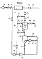
- FIG. 3 Such an installation is shown diagrammatically in FIG. 3.
- a device to be cleaned 10 which is for example a heat exchange, receiving a cold fluid (water) through an inlet pipe 11 by a pump 12, this fluid leaving the device through an outlet pipe 13.
- Valves 14 and 15 allow the device to be isolated in order to clean it.
- the cleaning installation comprises in parallel on the device 10 from the outlet to the inlet thereof a circuit composed successively of a liquid-solid separator 30, a storage silo 40, a metering device 45 and a cleaning pump 50.
- a pipe 60 furthermore connects the outlet of the device 10 and the inlet of the pump 50 and makes it possible to circulate in bypass when the fluid has the desired concentration of elements.
- a pipe 61 connects via a valve 62 the upper part of the separator to the pipe 60. It allows the liquid to be recycled until the complete separation of the elements from the fluid.
- a pipe 63 connects, via a valve 64, the top of the storage silo 40 to the pipe 60; it allows the concentration of the fluid.
- a pipe 65 isolated by a valve 66, allows the rejection of biological suspensions from cleaning.
- a pipe 70 starting from the top of the storage silo 40 allows the elements to fluidize.
- This pipe is connected to the base of the silo by a pipe 71 via a valve 72 and a pump 73.
- Valves 41, 51, 67 and 81 complete the device.
- the separator is isolated by closing the valves 31 and 62.
- the valves 12, 64, 41 and 72 are open; valve 67 is closed.
- the dosing in concentration of cleaning elements is carried out by the fluidization of a part of the elements contained in the storage silo 40.
- the fluidization is obtained by injecting a low flow of water with the pump 73.
- the concentration measurement is determined by the metering device 45.
- valves 31, 62, 64 and 41 are closed; the valves 12 and 67 are open.
- the cleaning is done by circulation of the fluid loaded with cleaning element outside the separator 30 and the storage silo 40.
- the concentration of elements is advantageously from 5 to 15%.
- the flow speed can be between 0.2 and 1.5 m / s for tubing with a diameter less than 8 mm, and between 0.8 and 4 m / s for tubing with a diameter greater than 8 mm.
- a cleaning time of 15 minutes is usually sufficient if it is repeated periodically (for example, monthly).
- the third phase consists in recovering the cleaning elements. To this end, the valves 12, 64, 41 and 72 are closed and the valves 31, 62, 67 are open.
- the elements are both cleaned and separated from the water in the separator 30.
- the waste is evacuated via the pipe 65 and the cleaning elements return to the storage silo 40.
- the installation can then be replenished with clean water and clean the installation by circulating the water in the separator and the piping 65.
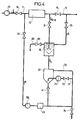
- the installation shown diagrammatically in FIG. 4, on the contrary allows the cleaning of a device without requiring the stopping of its operation. In addition, it only requires a low flow pump. It allows, by periodic tests on the heat exchange coefficient, to carry out cleaning phases of precise duration carried out correctly.
- the synthetic cleaning elements introduced into the cleaning circuit constituted by the separator 30, the silo 40, the doser 45 and the pump 50 pass through the exchanger 10 and carry with them the deposits.
- they are separated from the working fluid of the exchanger which joins the pipe 13 through a valve 35; a significant part of the waste is evacuated via the pipe 65.
- the flow extracted by this pipe is made up by a make-up through the valve 74.
- the synthetic cleaning elements return to the cleaning cycle until the end of the operation which is controlled by stopping the pump 50.
- the latter is of lower capacity than in the case of the installation of FIG. 3 since it only carries a low flow rate, of the order of 1/10 that of the exchanger pump.
Landscapes
- Engineering & Computer Science (AREA)
- Mechanical Engineering (AREA)
- Physics & Mathematics (AREA)
- Fluid Mechanics (AREA)
- General Engineering & Computer Science (AREA)
- Combustion & Propulsion (AREA)
- Chemical & Material Sciences (AREA)
- Cleaning In General (AREA)
- Control Of Vending Devices And Auxiliary Devices For Vending Devices (AREA)
- Detergent Compositions (AREA)
- Heat-Exchange Devices With Radiators And Conduit Assemblies (AREA)
- Input Circuits Of Receivers And Coupling Of Receivers And Audio Equipment (AREA)
- Cleaning By Liquid Or Steam (AREA)
- Compositions Of Oxide Ceramics (AREA)
- Inorganic Insulating Materials (AREA)
Priority Applications (1)
| Application Number | Priority Date | Filing Date | Title |
|---|---|---|---|
| AT81109896T ATE5746T1 (de) | 1980-12-01 | 1981-11-26 | Reinigungskoerper und reinigungsanlage zur anwendung dieses koerpers. |
Applications Claiming Priority (2)
| Application Number | Priority Date | Filing Date | Title |
|---|---|---|---|
| FR8025448 | 1980-12-01 | ||
| FR8025448A FR2495028A1 (fr) | 1980-12-01 | 1980-12-01 | Element de nettoyage et installation de nettoyage mettant en oeuvre cet element |
Publications (2)
| Publication Number | Publication Date |
|---|---|
| EP0053355A1 EP0053355A1 (fr) | 1982-06-09 |
| EP0053355B1 true EP0053355B1 (fr) | 1983-12-28 |
Family
ID=9248514
Family Applications (1)
| Application Number | Title | Priority Date | Filing Date |
|---|---|---|---|
| EP81109896A Expired EP0053355B1 (fr) | 1980-12-01 | 1981-11-26 | Elément de nettoyage et installation de nettoyage mettant en oeuvre cet élément |
Country Status (8)
| Country | Link |
|---|---|
| EP (1) | EP0053355B1 (enExample) |
| JP (1) | JPS57122299A (enExample) |
| AT (1) | ATE5746T1 (enExample) |
| CA (1) | CA1193108A (enExample) |
| DE (1) | DE3161804D1 (enExample) |
| ES (1) | ES8300518A1 (enExample) |
| FR (1) | FR2495028A1 (enExample) |
| PT (1) | PT74054B (enExample) |
Families Citing this family (17)
| Publication number | Priority date | Publication date | Assignee | Title |
|---|---|---|---|---|
| GB2181810B (en) * | 1983-11-23 | 1990-06-13 | Superior I D Tube Cleaners Inc | Tube cleaners. |
| JPS6438184A (en) * | 1987-08-01 | 1989-02-08 | Shizuo Sagawa | Method of cleaning pipe |
| JPH0212493U (enExample) * | 1988-07-06 | 1990-01-25 | ||
| ATA211090A (de) * | 1990-10-19 | 1996-05-15 | Industrieanlagen Planungs Und | Verfahren, reinigungskörper und reinigungsmittel zum reinigen von werkstücken |
| DE4244396C2 (de) * | 1992-12-29 | 1998-04-30 | Heron Sondermaschinen Und Steu | Verbindungsstück für die lösbare Verbindung zweier Profilstäbe, vorzugsweise aus Leichtmetall |
| EP0634229B1 (de) * | 1993-07-12 | 1998-10-07 | Promotec AG | Verfahren, Zusammensetzung und Vorrichtung zur Innenreinigung und Beschichtung von Rohrleitungen |
| US5685041A (en) * | 1996-02-14 | 1997-11-11 | Sivacoe; Orlande | Pipe pig with abrasive exterior |
| DE19883011B4 (de) * | 1998-08-06 | 2008-11-27 | E. Beaudrey & Cie. | Verfahren und Vorrichtung zur Steuerung bzw. Überwachung von in einem Wärmetauscher zur Reinigung desselben zirkulierenden festen Elementen |
| DE10135318A1 (de) * | 2001-07-19 | 2003-01-30 | Bayer Ag | Verfahren zum Entfernen von Ablagerungen an chemischen Reaktoren |
| US6945316B2 (en) | 2002-11-05 | 2005-09-20 | Taprogge Gmbh | System for cleaning tubes of heat exchangers and cleaning bodies therefor |
| DE10251736A1 (de) * | 2002-11-05 | 2004-05-13 | Taprogge Gmbh | System zum Reinigen von Rohren von Wärmetauschern |
| GB0421390D0 (en) * | 2004-09-25 | 2004-10-27 | Sadler Shaun W | System and apparatus for cleaning liquids |
| US8124697B2 (en) * | 2008-02-27 | 2012-02-28 | Westlake Longview Corporation | Method of preventing or reducing agglomeration on grid in fluidized-bed vessel |
| US8129482B2 (en) | 2008-02-27 | 2012-03-06 | Westlake Longview Corporation | Method of preventing or reducing polymer agglomeration on grid in fluidized-bed reactors |
| EP2689838A1 (en) * | 2012-07-26 | 2014-01-29 | Saudi Basic Industries Corporation | Method for cleaning a reactor |
| SG2013076799A (en) * | 2013-10-14 | 2015-05-28 | Hvs Engineering Pte Ltd | Method of cleaning a heat exchanger |
| JP6767066B1 (ja) * | 2020-02-07 | 2020-10-14 | 株式会社ミズキ | 洗浄ボールとその製造方法 |
Family Cites Families (9)
| Publication number | Priority date | Publication date | Assignee | Title |
|---|---|---|---|---|
| FR74154E (enExample) * | 1961-03-06 | |||
| US3011197A (en) * | 1957-07-18 | 1961-12-05 | Mobay Chemical Corp | Pipeline cleaning devices |
| FR1214853A (fr) * | 1958-05-02 | 1960-04-12 | Berguerand & Cie Ets | Pièces en caoutchouc, plastique ou toute matière souple, spécialement conçues pour le nettoyage des tuyauteries |
| DE1247359B (de) * | 1962-01-22 | 1967-08-17 | Hitachi Ltd | Reinigungsvorrichtung fuer Roehren-Waermetauscher |
| DE1281456B (de) * | 1962-05-02 | 1968-10-31 | Taprogge Fa Ludwig | Siebanordnung fuer Kondensatoranlagen mit Selbstreinigungseinrichtung |
| FR1449837A (fr) * | 1965-07-06 | 1966-05-06 | Tampon pour le nettoyage de conduites | |
| US3573985A (en) * | 1967-08-15 | 1971-04-06 | Western Decalta Petroleum Ltd | Method for cleaning pipelines |
| JPS534567B2 (enExample) * | 1973-05-28 | 1978-02-18 | ||
| DE3021697C2 (de) * | 1980-06-10 | 1982-11-11 | Taprogge Gesellschaft mbH, 4000 Düsseldorf | Reinigungskörper für die Innenreinigung von Röhrenwärmetauschern |
-
1980
- 1980-12-01 FR FR8025448A patent/FR2495028A1/fr active Granted
-
1981
- 1981-11-26 EP EP81109896A patent/EP0053355B1/fr not_active Expired
- 1981-11-26 DE DE8181109896T patent/DE3161804D1/de not_active Expired
- 1981-11-26 AT AT81109896T patent/ATE5746T1/de not_active IP Right Cessation
- 1981-11-27 PT PT74054A patent/PT74054B/pt unknown
- 1981-11-30 CA CA000391215A patent/CA1193108A/fr not_active Expired
- 1981-11-30 ES ES507574A patent/ES8300518A1/es not_active Expired
- 1981-11-30 JP JP56192694A patent/JPS57122299A/ja active Pending
Also Published As
| Publication number | Publication date |
|---|---|
| EP0053355A1 (fr) | 1982-06-09 |
| CA1193108A (fr) | 1985-09-10 |
| ES507574A0 (es) | 1982-11-01 |
| DE3161804D1 (en) | 1984-02-02 |
| ES8300518A1 (es) | 1982-11-01 |
| ATE5746T1 (de) | 1984-01-15 |
| FR2495028B1 (enExample) | 1984-08-24 |
| PT74054A (fr) | 1981-12-01 |
| PT74054B (fr) | 1983-11-22 |
| JPS57122299A (en) | 1982-07-30 |
| FR2495028A1 (fr) | 1982-06-04 |
Similar Documents
| Publication | Publication Date | Title |
|---|---|---|
| EP0053355B1 (fr) | Elément de nettoyage et installation de nettoyage mettant en oeuvre cet élément | |
| EP2897913B1 (fr) | Procédé de traitement d'eau comprenant une flottation combinée à une filtration gravitaire et installation correspondante | |
| FR2501054A1 (fr) | Procede et appareil pour nettoyer des bassins | |
| FR2638659A1 (fr) | Appareil de filtration comportant un dispositif de decolmatage par ultrasons et procede de decolmatage correspondant | |
| FR2729382A1 (fr) | Reacteur d'irradiation uv pour le traitement de liquides | |
| FR2990628A1 (fr) | Dispositif de filtration des eaux grises domestiques. | |
| EP0369851A1 (fr) | Dispositif de nettoyage d'un tube dans lequel circule un fluide | |
| JP7255830B2 (ja) | 管路洗浄方法及び管路洗浄システム | |
| EP1874695A2 (fr) | Procédé d'épuration d'effluent en réacteur anaérobie | |
| FR2982502A1 (fr) | Filtre desemboueur/clarificateur pour circuit ferme de fluide et procede associe de desembouage de circuit ferme de fluide | |
| EP0472459A1 (fr) | Procédé et installation de traitement d'agglomérats de particules solides en suspension dans un liquide, afin d'obtenir un mélange hétérogène pouvant circuler sans dépôts dans des canalisations de grande longueur | |
| FR3089822A1 (fr) | Dispositif d’injection de fluide dans un liquide | |
| FR3085744A1 (fr) | Echangeur thermique flexible comprenant un assemblage de sondes thermiques flexibles | |
| WO2019101454A1 (fr) | Systeme pour le traitement biologique des eaux | |
| FR3068030A1 (fr) | Dispositif de captation de particules ferreuses comprenant une enceinte dans laquelle est present au moins un barreau aimante amovible | |
| FR2941226A1 (fr) | Installation d'assainissement d'eau. | |
| FR2774110A1 (fr) | Chasse automatique par siphonnage et station d'epuration des eaux comportant une telle chasse | |
| EP2310272B1 (fr) | Système d'introduction de mortier dans un conteneur | |
| EP1944356A1 (fr) | Procédé et installation de chauffage de produit de brasserie | |
| FR2842580A1 (fr) | Procede de nettoyage manuel de drains d'un enrochement et outillage concu a cet effet | |
| EP2032314A2 (fr) | Outil de mise en place d'un joint dans une gorge, notamment pour dispositif de projection de jet d'eau | |
| BE570752A (enExample) | ||
| EP2977164B1 (fr) | Procédé de modification d'une structure en béton | |
| BE269326A (enExample) | ||
| EP4016040A1 (fr) | Dispositif et procédé pour mesurer le taux de réussite de la reproduction des poissons lithophiles |
Legal Events
| Date | Code | Title | Description |
|---|---|---|---|
| PUAI | Public reference made under article 153(3) epc to a published international application that has entered the european phase |
Free format text: ORIGINAL CODE: 0009012 |
|
| AK | Designated contracting states |
Designated state(s): AT BE CH DE FR GB IT LU NL SE |
|
| 17P | Request for examination filed |
Effective date: 19821111 |
|
| ITF | It: translation for a ep patent filed | ||
| GRAA | (expected) grant |
Free format text: ORIGINAL CODE: 0009210 |
|
| AK | Designated contracting states |
Designated state(s): AT BE CH DE FR GB IT LI LU NL SE |
|
| REF | Corresponds to: |
Ref document number: 5746 Country of ref document: AT Date of ref document: 19840115 Kind code of ref document: T |
|
| REF | Corresponds to: |
Ref document number: 3161804 Country of ref document: DE Date of ref document: 19840202 |
|
| PGFP | Annual fee paid to national office [announced via postgrant information from national office to epo] |
Ref country code: FR Payment date: 19840322 Year of fee payment: 4 |
|
| PGFP | Annual fee paid to national office [announced via postgrant information from national office to epo] |
Ref country code: CH Payment date: 19840813 Year of fee payment: 4 |
|
| PGFP | Annual fee paid to national office [announced via postgrant information from national office to epo] |
Ref country code: DE Payment date: 19840823 Year of fee payment: 4 |
|
| PGFP | Annual fee paid to national office [announced via postgrant information from national office to epo] |
Ref country code: SE Payment date: 19840930 Year of fee payment: 4 Ref country code: BE Payment date: 19840930 Year of fee payment: 4 |
|
| PLBE | No opposition filed within time limit |
Free format text: ORIGINAL CODE: 0009261 |
|
| STAA | Information on the status of an ep patent application or granted ep patent |
Free format text: STATUS: NO OPPOSITION FILED WITHIN TIME LIMIT |
|
| PG25 | Lapsed in a contracting state [announced via postgrant information from national office to epo] |
Ref country code: LU Free format text: LAPSE BECAUSE OF NON-PAYMENT OF DUE FEES Effective date: 19841130 |
|
| 26N | No opposition filed | ||
| PGFP | Annual fee paid to national office [announced via postgrant information from national office to epo] |
Ref country code: AT Payment date: 19861117 Year of fee payment: 6 |
|
| PGFP | Annual fee paid to national office [announced via postgrant information from national office to epo] |
Ref country code: NL Payment date: 19861130 Year of fee payment: 6 |
|
| PG25 | Lapsed in a contracting state [announced via postgrant information from national office to epo] |
Ref country code: AT Effective date: 19871126 |
|
| PG25 | Lapsed in a contracting state [announced via postgrant information from national office to epo] |
Ref country code: SE Effective date: 19871127 |
|
| PG25 | Lapsed in a contracting state [announced via postgrant information from national office to epo] |
Ref country code: LI Effective date: 19871130 Ref country code: CH Effective date: 19871130 Ref country code: BE Effective date: 19871130 |
|
| BERE | Be: lapsed |
Owner name: ALSTHOM-ATLANTIQUE Effective date: 19871130 |
|
| PG25 | Lapsed in a contracting state [announced via postgrant information from national office to epo] |
Ref country code: NL Effective date: 19880601 |
|
| NLV4 | Nl: lapsed or anulled due to non-payment of the annual fee | ||
| GBPC | Gb: european patent ceased through non-payment of renewal fee | ||
| PG25 | Lapsed in a contracting state [announced via postgrant information from national office to epo] |
Ref country code: FR Free format text: LAPSE BECAUSE OF NON-PAYMENT OF DUE FEES Effective date: 19880729 |
|
| REG | Reference to a national code |
Ref country code: CH Ref legal event code: PL |
|
| PG25 | Lapsed in a contracting state [announced via postgrant information from national office to epo] |
Ref country code: DE Effective date: 19880802 |
|
| REG | Reference to a national code |
Ref country code: FR Ref legal event code: ST |
|
| PG25 | Lapsed in a contracting state [announced via postgrant information from national office to epo] |
Ref country code: GB Effective date: 19881118 |
|
| EUG | Se: european patent has lapsed |
Ref document number: 81109896.1 Effective date: 19880913 |