EP0052895B1 - Vorrichtung zum Salzen und Reiben von rohen Schinken im allgemeinen - Google Patents
Vorrichtung zum Salzen und Reiben von rohen Schinken im allgemeinen Download PDFInfo
- Publication number
- EP0052895B1 EP0052895B1 EP81200974A EP81200974A EP0052895B1 EP 0052895 B1 EP0052895 B1 EP 0052895B1 EP 81200974 A EP81200974 A EP 81200974A EP 81200974 A EP81200974 A EP 81200974A EP 0052895 B1 EP0052895 B1 EP 0052895B1
- Authority
- EP
- European Patent Office
- Prior art keywords
- tunnel
- machine
- conveyor
- hams
- ham
- Prior art date
- Legal status (The legal status is an assumption and is not a legal conclusion. Google has not performed a legal analysis and makes no representation as to the accuracy of the status listed.)
- Expired
Links
- 150000003839 salts Chemical class 0.000 claims abstract description 44
- 235000013372 meat Nutrition 0.000 claims abstract description 15
- 210000000988 bone and bone Anatomy 0.000 claims abstract description 8
- 239000002184 metal Substances 0.000 claims 1
- 238000011084 recovery Methods 0.000 claims 1
- 241000283690 Bos taurus Species 0.000 description 10
- 210000003195 fascia Anatomy 0.000 description 4
- 229910000831 Steel Inorganic materials 0.000 description 2
- 238000005452 bending Methods 0.000 description 2
- 235000011194 food seasoning agent Nutrition 0.000 description 2
- 239000012528 membrane Substances 0.000 description 2
- 238000000034 method Methods 0.000 description 2
- 230000004048 modification Effects 0.000 description 2
- 238000012986 modification Methods 0.000 description 2
- 230000003204 osmotic effect Effects 0.000 description 2
- 230000035515 penetration Effects 0.000 description 2
- 230000008569 process Effects 0.000 description 2
- 235000015224 raw ham Nutrition 0.000 description 2
- 238000009938 salting Methods 0.000 description 2
- 239000010959 steel Substances 0.000 description 2
- 101100394230 Caenorhabditis elegans ham-1 gene Proteins 0.000 description 1
- 101100045395 Mus musculus Tap1 gene Proteins 0.000 description 1
- FAPWRFPIFSIZLT-UHFFFAOYSA-M Sodium chloride Chemical compound [Na+].[Cl-] FAPWRFPIFSIZLT-UHFFFAOYSA-M 0.000 description 1
- 230000008901 benefit Effects 0.000 description 1
- 230000008878 coupling Effects 0.000 description 1
- 238000010168 coupling process Methods 0.000 description 1
- 238000005859 coupling reaction Methods 0.000 description 1
- 239000000835 fiber Substances 0.000 description 1
- 230000005484 gravity Effects 0.000 description 1
- 230000001788 irregular Effects 0.000 description 1
- 210000003127 knee Anatomy 0.000 description 1
- 210000002414 leg Anatomy 0.000 description 1
- 239000000463 material Substances 0.000 description 1
- 239000011159 matrix material Substances 0.000 description 1
- 235000020989 red meat Nutrition 0.000 description 1
- 238000011144 upstream manufacturing Methods 0.000 description 1
Images


Classifications
-
- A—HUMAN NECESSITIES
- A23—FOODS OR FOODSTUFFS; TREATMENT THEREOF, NOT COVERED BY OTHER CLASSES
- A23B—PRESERVATION OF FOODS, FOODSTUFFS OR NON-ALCOHOLIC BEVERAGES; CHEMICAL RIPENING OF FRUIT OR VEGETABLES
- A23B4/00—Preservation of meat, sausages, fish or fish products
- A23B4/32—Apparatus for preserving using solids
- A23B4/325—Apparatus for preserving using solids with inorganic salts
-
- Y—GENERAL TAGGING OF NEW TECHNOLOGICAL DEVELOPMENTS; GENERAL TAGGING OF CROSS-SECTIONAL TECHNOLOGIES SPANNING OVER SEVERAL SECTIONS OF THE IPC; TECHNICAL SUBJECTS COVERED BY FORMER USPC CROSS-REFERENCE ART COLLECTIONS [XRACs] AND DIGESTS
- Y02—TECHNOLOGIES OR APPLICATIONS FOR MITIGATION OR ADAPTATION AGAINST CLIMATE CHANGE
- Y02A—TECHNOLOGIES FOR ADAPTATION TO CLIMATE CHANGE
- Y02A40/00—Adaptation technologies in agriculture, forestry, livestock or agroalimentary production
- Y02A40/90—Adaptation technologies in agriculture, forestry, livestock or agroalimentary production in food processing or handling, e.g. food conservation
Definitions
- This invention relates to a machine for automatically and continuously presalting raw hams intended for seasoning.
- the meat mass receives its required salt content by two basic operations.
- the first known as “presalting” comprises rubbing only the ham rind with moist salt, which by partly cutting into the rind initiates the osmotic process of penetration of the salt into the meat.
- Said first operation must be limited only to the rind without involving the bare red meat portions which surround the ham joint, known commonly as the bone.
- the object of the present invention is to provide a machine able to rub moist salt onto the raw ham rind, while protecting its lean part surrounding the joint.
- this is accomplished while satisfying a further requirement of the presalting operation, namely introducing the moist salt into the thin part close to the knee, known as the "shank", and maintaining it thereat.
- the design which attains this object consists of an approximately horizontal tunnel having its base rigid and its other walls deformable, and constituted by a rough heavy mesh arranged to allow the salt to pass and to rub it on to the ham surface, means being provided for feeding the ham through said tunnel with its shank disposed frontwards, and to protect the "bare" portion around the joint from contact with the salt.
- Means are also obviously provided for feeding the moist salt by feeding it from a collector disposed downstream of the tunnel to a hopper disposed upstream thereof.
- the deformable wall is constituted by a mesh of round steel rings inserted into each other in alternate directions.
- the presalting machine comprises a base frame 1 of welded tube, which is fitted lowerly with four wheels for its transfer in its areas of use.
- a framework 17 lies substantially above the central half of the upper horizontal face of the frame 1.
- a horizontal slide plate 34 provided centrally with a longitudinal slot which in cross-section is in the shape of an inverted T.
- the upper rectilinear portion of a slat-type conveyor belt 1 is designed to slide inside and said slot and to be supported therein, and passes over two end cog wheels 9, these latter having horizontal axes disposed transversely to the slide plate 34.
- said conveyor 15 is constituted by a plurality of small width slats pivoted together, their hinging pins emerging from both the longitudinal edges of the said salts, so that they become engaged by the end cog wheels 9.
- said conveyor 15 does not necessarily have to be of the slat type, but can be of any other convenient type, for example of the endless belt or chain type.
- the drive wheel is disposed at the rear end of the machine and is keyed on to a shaft which is rotatably mounted on the frame 1.
- a sprocket wheel about which a chain 10 passes and extends downwards where it is deviated over a further sprocket wheel provided on the exit shaft of a variable speed motor 4, this latter being disposed at the base of the rear end of the frame 1.
- a set of suitably equidistant shield-shaped pushers is fitted to the links of the conveyor 15.
- Each of said shield-shaped pushers comprises a substantially hemispherical hollow shell 12, the mouth of which is slightly flared outwards and always faces the transfer direction of the conveyor 15.
- each shield-shaped pusher there is connected the perimetral edge of an elastically deformable membrane 13, which is substantially of spherical cup configuration and is constituted of alimentary rubber.
- each individual shield-shaped pusher it is not necessary for each individual shield-shaped pusher to have a helmet configuration such as that heretofore described, but it is sufficient for its shape to be such as to completely cover the bare meat portion which encloses the bone of the hams 16.
- each shield-shaped pusher can be simply constituted by a convex plate slightly inclined in the transfer direction of the conveyor 15, and having its front or active surface covered with a convenient layer of elastically deformable alimentary rubber.
- Said helmet or convex plate is pivoted centrally to an arm 14 which is hinged in its turn at the front point of its connection base to the conveyor 15.
- connection base of said arm 14 is relatively large so that it rests against the lower rectilinear portion of the conveyor 15 to enable the helmet or convex plate to assume its working position as shown.
- said large base acts as a support for the helmet or convex plate when this latter lies on the upper rectilinear portion of the conveyor 15.
- each individual arm 14 is slightly inclined in the transfer direction of the conveyor 15.
- each retainer 35 is to house the shank of a ham 16.
- said positioning or centering elements 35 are each essentially constituted by a piece of round bar which is bent at a right angle and is slightly inclined to the corresponding portion of conveyor 15, its bending angle facing this latter.
- each retainer 35 has a distance between the base of each retainer 35 and the respective convex plate 12 .
- the distance between the base of each retainer 35 and the respective convex plate 12 is such as to be able to contain all lengths of normal hams 16.
- each retainer 35 is such as to be able to receive ham legs of different sizes.
- a horizontal conveyor belt 6 is provided between the lower rectilinear portion of the conveyor 15 and the base of the frame 1, and passes over two end rollers 7 which are disposed transversely to the frame 1.
- the upper rectilinear portion of the belt 8 moves in the opposite direction to that of the corresponding portion of the conveyor 15.
- the motion for the belt 8 is derived from that of the front cog wheel 9 by way of a chain 11.
- a hopper 18 On the front transverse face of the frame 17 there is disposed a hopper 18 in which a quantity of moist salt 19 is constantly present.
- the base of the hopper 18 is constituted by a horizontal trough, in which there is housed a worm 20, to one end of which there is keyed a sprocket wheel.
- a chain 21 passes around this latter and extends into the frame 1, where it is returned about a sprocket wheel keyed on to the exit shaft of a variable speed motor 3.
- a suitable aperture which communicates with a tube-encased worm 23 inclined to the vertical and disposed to the side of the front zone of the machine.
- the tube-encased worm 23 extends upwards to reach the top of the front zone of the framework 17.
- an electric motor 22 which by way of a suitable linkage rotates said tube-encased worm.
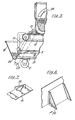
- a channel is defined along the plate 34 by the lower zones of the sides of the frame 17, for transferring the hams 16 during the presalting stage, as better shown in the accompanying Figure 2.
- each of said sides of the frame 17 there is disposed a set of elastically flexible vertical flaps 26 suitably spaced apart and formed from alimentary rubber.
- Each individual flap 26 is constituted by a sector of substantially trapezoidal shape, the oblique side of which faces the longitudinal central zone of said slide or transfer channel for the hams 16.
- each flap 26 which is disposed against the corresponding side of the frame 17 is conveniently fixed thereto, while to the rear of its lower horizontal side, this rear position relating to the transfer direction of the hams 16, there is provided a lamina or leaf spring, the purpose of which is to keep the corresponding flap 26 in its correct transverse vertical position when hams 16 are absent.
- the pocket 25 can be constructed of any suitable material, for example a natural fibre, and its apertures can have any configuration provided they allow the grains of moist salt to fall downwards when contact is made with the deformable pocket.
- said deformable perforated pocket is preferably constituted by a plurality of circular steel rings 30 disposed in a matrix configuration comprising a plurality of rows and a plurality of columns.
- the rings 30 of each row or column are coupled together, and these rings of said row or column are also coupled to the rings of the adjacent rows or columns, as can be better seen in Figure 3.
- the rings 30 are mobile relative to each other in practically all directions.
- the conveyor 1 5 is driven continuously by the variable speed motor 4, and the tube-encased worm 23 discharges the moist salt 19 either continuously or intermittently, according to requirements, into the deformable perforated pocket 25. Said moist salt is obviously taken from the hopper 18.
- each shield-shaped pusher 12 possesses for making small swinging movements relative to its arm 14 is extremely advantageous in that it enables the shield-shaped pusher 12 to adapt itself perfectly to the position and configuration of said meat portion which encloses the bone of a ham 16.
- the moist salt also makes contact with the cut portion of the ham shanks because the retainers or positioning elements 35 are open at their front and constantly move or urge against the deformable perforated pocket 25 so as to cause moist salt to fall and adhere to said cut portions.
- the machine according to the invention prevents the moist salt from coming into contact with said bare meat for the following reasons.
- each ham 16 is discharged from the machine, and the salt which is entrained by said ham falls on to the conveyor belt 6 and is conveyed into the hopper 18.
Landscapes
- Chemical & Material Sciences (AREA)
- Life Sciences & Earth Sciences (AREA)
- Engineering & Computer Science (AREA)
- Inorganic Chemistry (AREA)
- Wood Science & Technology (AREA)
- Zoology (AREA)
- Food Science & Technology (AREA)
- Polymers & Plastics (AREA)
- Meat, Egg Or Seafood Products (AREA)
- Preparation Of Fruits And Vegetables (AREA)
Claims (8)
Priority Applications (1)
| Application Number | Priority Date | Filing Date | Title |
|---|---|---|---|
| AT81200974T ATE8727T1 (de) | 1980-11-05 | 1981-09-01 | Vorrichtung zum salzen und reiben von rohen schinken im allgemeinen. |
Applications Claiming Priority (2)
| Application Number | Priority Date | Filing Date | Title |
|---|---|---|---|
| IT46899/80A IT1141738B (it) | 1980-11-05 | 1980-11-05 | Macchina presalatrice e strofinatrice per prosciutti crudi in genere |
| IT4689980 | 1980-11-05 |
Publications (3)
| Publication Number | Publication Date |
|---|---|
| EP0052895A2 EP0052895A2 (de) | 1982-06-02 |
| EP0052895A3 EP0052895A3 (en) | 1982-09-29 |
| EP0052895B1 true EP0052895B1 (de) | 1984-08-01 |
Family
ID=11260374
Family Applications (1)
| Application Number | Title | Priority Date | Filing Date |
|---|---|---|---|
| EP81200974A Expired EP0052895B1 (de) | 1980-11-05 | 1981-09-01 | Vorrichtung zum Salzen und Reiben von rohen Schinken im allgemeinen |
Country Status (5)
| Country | Link |
|---|---|
| EP (1) | EP0052895B1 (de) |
| AT (1) | ATE8727T1 (de) |
| DE (1) | DE3165237D1 (de) |
| ES (1) | ES8203193A1 (de) |
| IT (1) | IT1141738B (de) |
Families Citing this family (3)
| Publication number | Priority date | Publication date | Assignee | Title |
|---|---|---|---|---|
| IT1181091B (it) * | 1984-02-08 | 1987-09-23 | Soncini A Macch Spa | Macchina sfregatrice per la presalatura di prosciutti crudi in genere |
| ES2301374B1 (es) * | 2006-07-21 | 2009-05-01 | Jamones Caseros Agapito, S.L. | Instalacion para salado de jamones. |
| CN109287721B (zh) * | 2018-09-18 | 2023-11-14 | 贵州杨老奶食品有限公司 | 一种自动抹盐滚揉的火腿加工机及其使用方法 |
Family Cites Families (3)
| Publication number | Priority date | Publication date | Assignee | Title |
|---|---|---|---|---|
| US1825205A (en) * | 1929-08-22 | 1931-09-29 | Allbright Nell Co | Meat trimming apparatus |
| FR1151486A (fr) * | 1956-01-18 | 1958-01-30 | Auto-frotteur pour jambons | |
| IT1067877B (it) * | 1976-07-15 | 1985-03-21 | Soncini Alberto | Massaggiatrice a ciclo continuo per prosciutti crudi |
-
1980
- 1980-11-05 IT IT46899/80A patent/IT1141738B/it active
-
1981
- 1981-07-14 ES ES503924A patent/ES8203193A1/es not_active Expired
- 1981-09-01 EP EP81200974A patent/EP0052895B1/de not_active Expired
- 1981-09-01 AT AT81200974T patent/ATE8727T1/de not_active IP Right Cessation
- 1981-09-01 DE DE8181200974T patent/DE3165237D1/de not_active Expired
Also Published As
| Publication number | Publication date |
|---|---|
| ATE8727T1 (de) | 1984-08-15 |
| DE3165237D1 (en) | 1984-09-06 |
| IT1141738B (it) | 1986-10-08 |
| ES503924A0 (es) | 1982-04-16 |
| IT8046899A0 (it) | 1980-11-05 |
| EP0052895A2 (de) | 1982-06-02 |
| EP0052895A3 (en) | 1982-09-29 |
| ES8203193A1 (es) | 1982-04-16 |
Similar Documents
| Publication | Publication Date | Title |
|---|---|---|
| US4551885A (en) | Fish decapitator and eviscerator | |
| EP0576181A2 (de) | Eiersammelanlage | |
| EP0052895B1 (de) | Vorrichtung zum Salzen und Reiben von rohen Schinken im allgemeinen | |
| KR20190048066A (ko) | 역회전 컨베이어에 의한 토양 분리 기능을 갖는 구근류 수확장치 | |
| ES2278954T3 (es) | Dispositivo y metodo para cortar carne. | |
| US3810512A (en) | Harvesting apparatus for removing crops from plants or vines | |
| CN104307593A (zh) | 冰糖破碎系统 | |
| US5320033A (en) | Apparatus for top and tailing vegetables | |
| EP1167248A1 (de) | Förderer | |
| CA1097583A (en) | Unloader for a horizontal silo | |
| US20160031652A1 (en) | Fruit and vegetable transport system for a harvesting machine and harvesting machine that includes said system | |
| US3972091A (en) | Device for severing the heads of fishes | |
| SU923348A3 (ru) | Способ ориентированной подачи в рыборазделочные машины рыб и устройство дл ориентированной подачи в рыборазделочные машины рыб | |
| JPH0342041B2 (de) | ||
| US2894340A (en) | Oyster digger | |
| JP2000106728A (ja) | 農産物収穫機 | |
| SU1127814A1 (ru) | Устройство дл растаривани мешков с сыпучим материалом | |
| WO1989007892A1 (en) | A method for transferring fish fillets between two conveyor belts and a device for accomplishing the method | |
| US3724362A (en) | Article feeding and treating apparatus | |
| US699908A (en) | Band-cutter and feeder for threshing-machines or grain-separators. | |
| US3217766A (en) | Handling and transfer mechanism for small elongate articles | |
| RU1775088C (ru) | Способ ориентированной подачи к режущим инструментам рыбы и устройство дл его осуществлени | |
| DK143833B (da) | Apparat til behandling af saltet krydret eller paa anden maade tilberedt fisk,fortrinsvis sild | |
| EP0888971A1 (de) | Automatische Schachtelbefülleinrichtung | |
| SU1126233A1 (ru) | Соргоуборочна машина |
Legal Events
| Date | Code | Title | Description |
|---|---|---|---|
| PUAI | Public reference made under article 153(3) epc to a published international application that has entered the european phase |
Free format text: ORIGINAL CODE: 0009012 |
|
| AK | Designated contracting states |
Designated state(s): AT BE CH DE FR GB IT LU NL SE |
|
| PUAL | Search report despatched |
Free format text: ORIGINAL CODE: 0009013 |
|
| AK | Designated contracting states |
Designated state(s): AT BE CH DE FR GB IT LU NL SE |
|
| 17P | Request for examination filed |
Effective date: 19830129 |
|
| ITF | It: translation for a ep patent filed | ||
| GRAA | (expected) grant |
Free format text: ORIGINAL CODE: 0009210 |
|
| AK | Designated contracting states |
Designated state(s): AT BE CH DE FR GB IT LI LU NL SE |
|
| PG25 | Lapsed in a contracting state [announced via postgrant information from national office to epo] |
Ref country code: SE Effective date: 19840801 Ref country code: NL Effective date: 19840801 Ref country code: LI Effective date: 19840801 Ref country code: CH Effective date: 19840801 Ref country code: BE Effective date: 19840801 Ref country code: AT Effective date: 19840801 |
|
| REF | Corresponds to: |
Ref document number: 8727 Country of ref document: AT Date of ref document: 19840815 Kind code of ref document: T |
|
| REF | Corresponds to: |
Ref document number: 3165237 Country of ref document: DE Date of ref document: 19840906 |
|
| ET | Fr: translation filed | ||
| PG25 | Lapsed in a contracting state [announced via postgrant information from national office to epo] |
Ref country code: LU Free format text: LAPSE BECAUSE OF NON-PAYMENT OF DUE FEES Effective date: 19840930 |
|
| REG | Reference to a national code |
Ref country code: CH Ref legal event code: PL |
|
| NLV1 | Nl: lapsed or annulled due to failure to fulfill the requirements of art. 29p and 29m of the patents act | ||
| PG25 | Lapsed in a contracting state [announced via postgrant information from national office to epo] |
Ref country code: DE Effective date: 19850601 |
|
| PLBE | No opposition filed within time limit |
Free format text: ORIGINAL CODE: 0009261 |
|
| STAA | Information on the status of an ep patent application or granted ep patent |
Free format text: STATUS: NO OPPOSITION FILED WITHIN TIME LIMIT |
|
| 26N | No opposition filed | ||
| GBPC | Gb: european patent ceased through non-payment of renewal fee | ||
| PG25 | Lapsed in a contracting state [announced via postgrant information from national office to epo] |
Ref country code: GB Effective date: 19881118 |
|
| PGFP | Annual fee paid to national office [announced via postgrant information from national office to epo] |
Ref country code: FR Payment date: 19910801 Year of fee payment: 11 |
|
| ITTA | It: last paid annual fee | ||
| PG25 | Lapsed in a contracting state [announced via postgrant information from national office to epo] |
Ref country code: FR Effective date: 19930528 |
|
| REG | Reference to a national code |
Ref country code: FR Ref legal event code: ST |