EP0052269B1 - Doppelspannung-Schaltanordnung für eine Röntgenröhre - Google Patents
Doppelspannung-Schaltanordnung für eine Röntgenröhre Download PDFInfo
- Publication number
- EP0052269B1 EP0052269B1 EP81109054A EP81109054A EP0052269B1 EP 0052269 B1 EP0052269 B1 EP 0052269B1 EP 81109054 A EP81109054 A EP 81109054A EP 81109054 A EP81109054 A EP 81109054A EP 0052269 B1 EP0052269 B1 EP 0052269B1
- Authority
- EP
- European Patent Office
- Prior art keywords
- voltage
- ray tube
- bias voltage
- switch means
- source
- Prior art date
- Legal status (The legal status is an assumption and is not a legal conclusion. Google has not performed a legal analysis and makes no representation as to the accuracy of the status listed.)
- Expired
Links
- 230000009977 dual effect Effects 0.000 title description 11
- 239000004065 semiconductor Substances 0.000 claims description 5
- 230000001419 dependent effect Effects 0.000 claims description 3
- 239000000654 additive Substances 0.000 claims description 2
- 230000000996 additive effect Effects 0.000 claims description 2
- 230000008878 coupling Effects 0.000 claims 2
- 238000010168 coupling process Methods 0.000 claims 2
- 238000005859 coupling reaction Methods 0.000 claims 2
- 230000003213 activating effect Effects 0.000 claims 1
- 238000002601 radiography Methods 0.000 description 10
- 238000010586 diagram Methods 0.000 description 7
- 238000003384 imaging method Methods 0.000 description 7
- 238000002594 fluoroscopy Methods 0.000 description 6
- 238000000034 method Methods 0.000 description 6
- 210000003484 anatomy Anatomy 0.000 description 5
- 238000011961 computed axial tomography Methods 0.000 description 5
- 230000002123 temporal effect Effects 0.000 description 5
- 239000000463 material Substances 0.000 description 4
- 238000004804 winding Methods 0.000 description 4
- ZCYVEMRRCGMTRW-UHFFFAOYSA-N 7553-56-2 Chemical compound [I] ZCYVEMRRCGMTRW-UHFFFAOYSA-N 0.000 description 3
- 230000008901 benefit Effects 0.000 description 3
- 210000004204 blood vessel Anatomy 0.000 description 3
- 210000000988 bone and bone Anatomy 0.000 description 3
- 230000001276 controlling effect Effects 0.000 description 3
- 238000001914 filtration Methods 0.000 description 3
- 229910052740 iodine Inorganic materials 0.000 description 3
- 239000011630 iodine Substances 0.000 description 3
- 210000004872 soft tissue Anatomy 0.000 description 3
- 206010028980 Neoplasm Diseases 0.000 description 2
- OAICVXFJPJFONN-UHFFFAOYSA-N Phosphorus Chemical compound [P] OAICVXFJPJFONN-UHFFFAOYSA-N 0.000 description 2
- 238000002083 X-ray spectrum Methods 0.000 description 2
- 230000000670 limiting effect Effects 0.000 description 2
- 238000004519 manufacturing process Methods 0.000 description 2
- 239000011159 matrix material Substances 0.000 description 2
- 230000002441 reversible effect Effects 0.000 description 2
- 230000001960 triggered effect Effects 0.000 description 2
- 238000012800 visualization Methods 0.000 description 2
- 230000002238 attenuated effect Effects 0.000 description 1
- 238000000205 computational method Methods 0.000 description 1
- 238000010276 construction Methods 0.000 description 1
- 239000002872 contrast media Substances 0.000 description 1
- 230000005684 electric field Effects 0.000 description 1
- 238000002347 injection Methods 0.000 description 1
- 239000007924 injection Substances 0.000 description 1
- 239000012212 insulator Substances 0.000 description 1
- 238000010253 intravenous injection Methods 0.000 description 1
- PNDPGZBMCMUPRI-UHFFFAOYSA-N iodine Chemical compound II PNDPGZBMCMUPRI-UHFFFAOYSA-N 0.000 description 1
- 150000002497 iodine compounds Chemical class 0.000 description 1
- 238000012423 maintenance Methods 0.000 description 1
- 239000002184 metal Substances 0.000 description 1
- 239000000203 mixture Substances 0.000 description 1
- 210000000056 organ Anatomy 0.000 description 1
- 230000036961 partial effect Effects 0.000 description 1
- 230000002829 reductive effect Effects 0.000 description 1
- 230000001105 regulatory effect Effects 0.000 description 1
- 230000004044 response Effects 0.000 description 1
- 238000007493 shaping process Methods 0.000 description 1
- 239000007787 solid Substances 0.000 description 1
- 238000001228 spectrum Methods 0.000 description 1
- 239000000126 substance Substances 0.000 description 1
- 230000001360 synchronised effect Effects 0.000 description 1
Images

Classifications
-
- A—HUMAN NECESSITIES
- A61—MEDICAL OR VETERINARY SCIENCE; HYGIENE
- A61B—DIAGNOSIS; SURGERY; IDENTIFICATION
- A61B6/00—Apparatus or devices for radiation diagnosis; Apparatus or devices for radiation diagnosis combined with radiation therapy equipment
- A61B6/48—Diagnostic techniques
- A61B6/482—Diagnostic techniques involving multiple energy imaging
-
- A—HUMAN NECESSITIES
- A61—MEDICAL OR VETERINARY SCIENCE; HYGIENE
- A61B—DIAGNOSIS; SURGERY; IDENTIFICATION
- A61B6/00—Apparatus or devices for radiation diagnosis; Apparatus or devices for radiation diagnosis combined with radiation therapy equipment
- A61B6/02—Arrangements for diagnosis sequentially in different planes; Stereoscopic radiation diagnosis
-
- A—HUMAN NECESSITIES
- A61—MEDICAL OR VETERINARY SCIENCE; HYGIENE
- A61B—DIAGNOSIS; SURGERY; IDENTIFICATION
- A61B6/00—Apparatus or devices for radiation diagnosis; Apparatus or devices for radiation diagnosis combined with radiation therapy equipment
- A61B6/40—Arrangements for generating radiation specially adapted for radiation diagnosis
- A61B6/405—Source units specially adapted to modify characteristics of the beam during the data acquisition process
-
- H—ELECTRICITY
- H05—ELECTRIC TECHNIQUES NOT OTHERWISE PROVIDED FOR
- H05G—X-RAY TECHNIQUE
- H05G1/00—X-ray apparatus involving X-ray tubes; Circuits therefor
- H05G1/08—Electrical details
- H05G1/26—Measuring, controlling or protecting
- H05G1/30—Controlling
- H05G1/32—Supply voltage of the X-ray apparatus or tube
-
- H—ELECTRICITY
- H05—ELECTRIC TECHNIQUES NOT OTHERWISE PROVIDED FOR
- H05G—X-RAY TECHNIQUE
- H05G1/00—X-ray apparatus involving X-ray tubes; Circuits therefor
- H05G1/08—Electrical details
- H05G1/56—Switching-on; Switching-off
Definitions
- This invention relates to a system for controlling an x-ray tube to emit alternate low and high photon energy x-ray pulses whose photon energy is determined by the alternate voltage drop across the tube during the pulse and whose intensity is dependent on the current passing through the tube during respective pulses.
- a system for instance known from US-A-4 029 963.
- An occasion for using a sequence of x-ray pulses at different energies is when it is desirable to selectively suppress or enhance the contribution to an x-ray image from a certain material.
- One instance is the imaging of body structures containing small amounts of an x-ray opaque dye, for example an iodine compound.
- Applications include the imaging of blood vessels opacified by intravenous injections of dye, or the imaging of tumors and/or organs slightly opacified by a dye.
- the low image contrast of the iodine-containing region can be masked by overlying and underlying bone or soft tissue structures and be made very difficult to see.
- Energy subtraction as the method of combining images at different x-ray energies is called, can enhance the contrast of one material, for example iodine, with respect to that of other materials, for example bone and/or soft tissue, and greatly improve the visibility of the structures of interest.
- Another application of energy subtraction may be in separating the contributions to an image due to bony structures from those due to soft tissue structures, for example in chest imaging.
- a sequence of x-ray pulses at different energies can also be used in computerized tomographic (CT) imaging.
- CT computerized tomographic
- the x-rays of different energies can be used to provide information on the chemical composition as well as density of a transverse section.
- the use of pulses at different energies also has the benefit of reducing certain beam-hardening artifacts in CT.
- temporal subtraction An alternative to energy subtraction for the improved visualization of administered contrast agents is temporal subtraction.
- temporal subtraction images taken before and after the injection of the iodinated dye are subtracted.
- the basic limitation of temporal subtraction is that the images being combined are separated in time by several seconds, and any motion that occurred between the acquisition of the two images will result in mis-registration artifacts in the image.
- temporal subtraction is not well suited to imaging contrast-producing materials that are slowly or not at all time varying, for example, bones or iodine dye sequestered by tumors.
- the images for energy subtraction are gathered in rapid time sequence little or no motion could have occurred during the image acquisition time and subtraction images with no mis-registration artifacts can be produced. What is required, then, is a means by which the average photon energy of the x-ray beam can be switched very quickly.
- the average energy of an x-ray beam can be affected by added x-ray filtration, and multi- energy methods using switching filters have been described. However, in order to change the x-ray energy significantly, heavy filtration is required and the resulting x-ray intensity is greatly reduced. A preferred method is to change both the x-ray filtration as well as the voltage at which the x-rays are produced.
- the required x-ray switching system should rapidly change both the x-ray tube peak kilovoltage (kVp) as well as the tube current (mA).
- An object of the present invention as claimed is to provide an x-ray tube switching circuit which enables rapid and accurate changing of both the x-ray tube peak kilovoltage and the tube current in a plurality of steps and at high repetition rates.
- an x-ray tube comprising an anode target, a filament and a control element, commonly called a grid is used.
- two negative bias voltage sources are provided each of which is adapted for providing a different voltage.
- the bias voltage sources are arranged in what is essentially a series circuit between the control element and cathode filament of the tube. Shunting switches are connected across the output of the bias voltage sources. In one operational mode, when both shunting switches are nonconducting, the sum of the bias voltages is applied between the control grid and filament of the tube to thereby make the x-ray tube non-conductive, or, in other words, to cut off cathode electron emission.
- Dynamic characteristics of the x-ray tube are predetermined by inserting a selected amount of resistance in the anode-to-cathode high voltage supply circuit of the x-ray tube.
- the dynamic characteristics of the x-ray tube are plotted in a manner which is typical of vacuum tubes.
- the plot shows the x-ray tube current and voltage drop across the tube that will prevail at various bias voltages for a variety of load lines.
- the first bias voltage source is shunted the second bias voltage source remains effective and the voltage drop and current can be determined from the dynamic characteristics plot.
- the x-ray tube current and voltage can be determined.
- both switching circuits When both switching circuits are triggered into a conductive state and both bias voltage sources are shunted, near zero bias voltage is applied to the x-ray tube control grid.
- the x-ray tube current then changes as desired, as compared with the previously discussed biasing conditions, and the tube voltage changes as well.
- the apparatus shown in FIGURE 1 is for making computed axial tomography and computed scanned projection radiography examinations of a patient.
- Computed scanned projection radiography provides an image of a patient's anatomy which can be displayed on a television monitor and which is analogous to the kind of image which is obtained in conventional radiography where an x-ray beam is projected through a body and is recorded on film.
- the patient 10 being examined is supine on an x-ray transmissive table top 11.
- the top 11 is mounted on a support 12 for being translated at a constant rate in the longitudinal direction, that is, lengthwise of the patient.
- An x-ray tube not visible in FIGURE 1, is contained in a casing 13 and is shown in a fixed position above the patient for the purposes of conducting computed scanned projection radiography.
- the tube casing is mounted on a ring 14 in this particular machine for being rotated around the patient when computed axial tomography is to be performed.
- An x-ray beam collimator 15, is coupled to the x-ray tube casing for shaping the emerging x-ray beam into a thin fan-shaped or diverging x-ray beam 16.
- the x-ray beam projects transversely through the patient and the direction in which the patient or source and detector are moved relatively during the scan is perpendicular to the plane of the beam.
- a slot 17 in the bottom of the collimator symbolizes the cross-sectional shape of the beam.
- An x-ray detector 18 is supported on ring 14 below the patient for orbiting around the patient jointly with the x-ray tube casing when computed axial tomography is being performed. However, for scanned projection radiography which is presently being considered, the detector and x-ray tube are held in a fixed position.
- the detector 18 may be one of the well-known gas-filled ionization or solid state scintillation types which are used in computed axial tomography. Detectors of this type have an array of cells or individual detector elements which detect the rays that make up the fan-shaped x-ray beam 16 after the rays have been attenuated differentially by having passed through the body of the patient.
- the detector has an x-ray transmissive window 18' which allows the rays to pass to the array of individual detector elements, not visible, in detector 18.
- x-ray beam 16 is pulsed on and off at a high rate, such as sixty times per second or even higher, while the patient is being translated longitudinally at a constant speed through the beam.
- a high rate such as sixty times per second or even higher
- a set of signals indicative of the attenuation by a slice of the patient which is in the beam is produced.
- These signals are provided to a data acquisition system (DAS) symbolized by the block marked 19.
- DAS data acquisition system
- the DAS preamplifies the signals, converts them to digital form and multiplexes them to a digital computer 20.
- the computer is programmed with a suitable algorithm to .use the attenuation data obtained in the various slices of the anatomy to develop the data with which is visible image of the length of the scanned region can be constructed.
- the computer delivers the reconstruction data to a display controller 21 of the type commonly used in computed axial tomography systems.
- a memory not shown, in the display controller holds the digital signals, representative of picture elements (pixels).
- the controller is adapted for reading out the digital pixel signals from the memory matrix on a line-by-line basis and it converts them to corresponding analog video signals for display in the raster scan mode on a television monitor 22.
- the analog video images may also be recorded in a video disc recorder 23 so the images can be viewed at any future time.
- the new dual energy switching system comes into play, for example, when it is desired to produce energy subtracted projection radiography images to enable better visualization of parts of the anatomy such as blood vessels containing some x-ray opaque medium.
- This techniques requires providing a sequence of low and high energy x-ray pulses so that each slice of the body is interrogated by x-ray of both spectra.
- the system is synchronized in such a manner that the computer is provided with a set of signals for each low x-ray energy pulse and a set for each high energy pulse.
- the computer can combine the signals corresponding to the low and high energy pulses and provide a set of signals to the display controller for enabling display of the subtracted image on the monitor shortly after the translational scan is completed.
- FIGURE 2 shows a digital fluoroscopy system which provides another example of a system in which the new switching system may be used.
- a patient 25 is supported on an x-ray transmissive table top 26.
- the x-ray tube generally designated by the numeral 27, is located beneath the x-ray table 26.
- a schematically represented collimator 28 defines the x-ray beam field.
- the x-ray tube comprises an anode 29, an electron emissive filament 30 and a control element or grid 31.
- the x-ray power supply is symbolized by the block marked 24 and would include the dual energy switching system which will be described in detail later.
- the system in FIGURE 2 is designed for performing both temporal and energy subtracting digital fluoroscopy.
- the operation in the dual energy subtraction mode will now be described to illustrate the system concepts.
- the x-ray tube is controlled to provide pairs of low energy and high energy x-ray pulses in a repeatable sequence. Pulsed beams in a pair fall on the input screen 32 of an x-ray image intensifier 33.
- the image intensifier converts the consecutive high and low or low and high energy x-ray images to a series of minified visible images which appear on a phosphor screen 34.
- a collimating lens 35 is aligned with the phosphor screen and with the input lens of a television camera 36.
- the television camera is operated synchronously with the x-ray pulses to produce analog video waveforms representative of the respective low and high energy x-ray pulses.
- the analog signals are transmitted by way of a bus 37 to an analog-to-digital (A/D) converter 38.
- A/D analog-to-digital
- the converted image data corresponding with a pulse at one energy is delivered to a first memory 39 and the data representative of an image at the other x-ray energy is transmitted to a second memory 40.
- the picture element (pixel) data for both images are provided to a computer 41 which is operative to combine the pixel data representative of the low and high x-ray energy images and to produce a matrix of subtracted pixel signals.
- the signals representative of the subtracted images may again be provided by means of a bus 42 to a display controller 43.
- a display controller converts the digital pixel-representative signals to corresponding analog video signals on a line-by-line basis for driving a television monitor 44 on whose screen the subtracted image is displayed.
- a video disc recorder 45 can be supplied with the output video signals to enable future display of the subtracted images on the monitor.
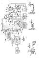
- the x-ray tube power supply comprises a variable three-phase autotransformer which is so labelled and is represented by the block marked 50.
- the ac power lines leading to the 3-phase autotransformer are marked 51.
- a tap switch mechanism 52 is provided for switching taps on the autotransformer to provide any desired output voltage.
- the output lines 53 from the autotransformer are run through a primary disconnect switch 54 which, in turn, supplies the Y-connected primary winding of a 3- phase transformer 55.
- the transformer will have a Y-primary and a delta-Y connected secondary winding.
- the output lines 56 and 57 of the transformer are connected to full-wave rectifier bridges 58 and 58', respectively.
- the rectifier bridges are series-connected and a point 59 between them is grounded. This is a good place to locate the meter 59' which measures the mA flowing through the x-ray tube since it is desirable to have meters at ground potential in the interest of safety.
- the total dc output voltage from the rectifiers appears between lines 60 and 61.
- the voltages between line 60 (+HV) and ground point 59 and between line 61 (-HV) and ground point 59 may be considered to be about equal to each other for present purposes and to be equal to about one-half of the total voltage although perfect symmetry is not absolutely necessary.
- the maximum total no-load voltage between lines 60 and 61 may be 150 kilovolts or whatever maximum voltage one may want on the x-ray tube in a particular case.
- positive line 60 would be at about 75 peak kilovolts (kVp) above ground and negative line 61 will be at 75 kVp below ground potential at the maximum voltage of the system in this numerical example.
- having the power line voltages symmetrical or nearly so with respect to ground reduces the insulating requirements of the system.
- the x-ray tube is designated generally by the numeral 62. It comprises an evacuated envelope 63, an anode target 64, a thermionic filament 65 and a control element or grid in the form of a focusing cup 66.
- the metal focusing cup 66 is shown in greater detail in FIGURE 4. It has a stepped recess 67 which shapes the electric field around the filament 65 for focusing purposes.
- the filament is a helical coil of wire which is viewed axially in FIGURE 4.
- the lead wires 68 and 69 for passing current through filament 65 run through an insulator 70.
- filament 65 is supplied from the secondary winding of a filament transformer 71 whose primary winding is energized from a filament current control logic circuit symbolized by the block marked 72.
- the current control is basically conventional in that it permits adjusting the magnitude of the current through the filament for setting the temperature of the filament and, hence, its maximum electron emissivity.
- the maximum amount of current that can flow between anode 64 and filament 65 of the x-ray tube depends on filament temperature, as is well known.
- the positive high voltage, +HV, is applied to the x-ray tube anode 64 by way of line 60 which has an adjustable resistor 74 in it.
- the negative high voltage, -HV, line 61 also has an adjustable resistor 75 in it and it leads to filament 65 by way of lines 76 and 69.
- the wipers of adjustable resistors 74 and 75 are ganged for being driven concurrently by a reversible motor 77.
- the total plate or anode impedance of the x-ray tube is the sum of the two resistors plus the internal impedance of the high voltage supply.
- the settings of adjustable resistors 74 and 75 determines the voltage drop between the anode 64 and cathode filament 65 of the x-ray tube when the tube is conducting.
- the voltage drop across the tube determines the energy of the x-ray photons produced.
- these adjustable resistors are involved in determining the voltage drop across the x-ray tube for the low and high energy x-ray pulses and, in conjunction with the control element biasing voltages, the adjustable resistors are determinative of the current that will flow through the x-ray tube during the low and high energy pulses.
- the peak voltage drop desired across the x-ray tube itself depends on the anode circuit impedance and is selected by operating motor 77 through the agency of its controller 78 which is marked with the legend kVp select. At least one adjustable resistor 74 or 75 is required but two are used here for the sake of maintaining symmetry.
- Bias supply 81 contains a dc rectifier circuit, not visible, that is supplied with ac through a transformer 83.
- the supply has a negative voltage line 84 and a positive voltage line 85 leading from it.
- a line 88 leads from the negative side of the bias supply 81 to control grid or focusing cup 66 of the x-ray tube and there is a grid resistor 89 in this line.
- Phototransistor 87 is made alternately conductive and non-conductive by triggering it with a pulsed light-emitting diode (LED) 90. When the LED is not emitting light, the phototransistor 87 is nonconducting and the bias voltage from source 81 is applied to focusing cup 66. When LED 90 is emitting, phototransistor 87 becomes conductive and short-circuits or shunts the bias voltage of supply 81 from the control grid or focusing cup 66. Resistor 86 limits the short circuit current to a tolerable value.
- Bias voltage source 82 and its associated circuitry is similar in construction to the source and circuitry just described although it may be set to provide a bias voltage of different value.
- Bais source 82 has a negative output line 94 and a positive voltage output line 95.
- This resistor is in a circuit loop which includes semiconductor switch means represented by a phototransistor 97 that connects to the positive side of bias voltage supply 82 by way of line 95.
- An LED 98 is provided for triggering phototransistor 97 from a nonconductive state to a conductive state whereupon it will shunt or short-circuit the bias supply 82.
- a diode 99 is connected across the emitter and collector of phototransistor 97.
- Bias voltage source 82 is supplied with ac through a transformer 100.
- Transformers 83 for bias supply 81 and 100 for bias supply 82 are provided with primary voltages from a bias control circuit which is symbolized by the block marked 101. Bias control allows for setting the voltages desired from bias voltage sources 81 and 82.
- the phototransistors 87 and 97 are triggered on an off by pulsing LEDs 90 and 98 to produce the desired low energy and high energy x-ray pulse levels and durations.
- the triggering circuit for the LEDs is symbolized by the block 102 which is labelled bias pulse on/off control.
- both semiconductor switch means 87 and 97 are non- conductive and the two negative bias voltages from sources-81 and 82 are not shunted and are additive to produce a. sufficiently high bias voltage on focusing cup 66 to cut off electron emission from filament 65 in which case the x-ray tube is non-conductive and no x-rays are produced.
- bias voltage V1 from source 81 is shunted leaving only the bias voltage V2 from source 82 effective in which case a predetermined current will flow through the x-ray tube and there will be a particular voltage drop across it, thus providing an x-ray pulse at one energy level.
- both bias supplies will be shunted by the switch means becoming conductive, resulting in near zero bias voltage being applied to the control electrode or focusing cup 66 of the x-ray tube. This will result in a different amount of current through the x-ray tube and a particular voltage drop across it, thus providing an x-ray pulse at a different level.
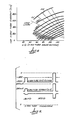
- Voltage drops between the anode and cathode of the x-ray tube and the current through the tube, if any, under the various biasing conditions just discussed are established in accordance with the dynamic characteristics of the x-ray tube with various load lines being drawn on the plot.
- One of the load lines which, as in FIGURE 8, will serve as a basis for illustration is marked 105. Any load line represents variation of the anode current with voltage for a selected load resistance.
- Load line 105 like the others next to it represents the resistive values of adjustable resistors 74 and 75 in FIGURE 3 plus the internal impedance of the high voltage generators including their associated filter circuits 106 and 107.
- typical bias voltage lines are labelled, for the sake of this example, with the negative voltage they represent.
- the ordinate of the plot represents current through the x-ray tube and the abscissa represents voltage drop across the x-ray tube.
- the load lines intersect the abscissa axis at a peak kilovoltage of 150 kilovolts in this example but, in any case, the intersection would occur at a voltage corresponding with the no-load voltage between high voltage lines 60 and 61.
- the maximum voltage applied across the x-ray tube under no-load conditions is the power supply voltage which is 150 kVp in this numerical example.
- load line 105 As an example, with the bias voltage V2 from source 82 to set at -1800 volts, the load line intersects this bias voltage line at an x-ray tube current of 250 mA and 135 kVp drop across the tube. This is the mA and kVp of the x-ray tube when bias voltage V1 is shunted and only bias voltage V2 from source 82 is effective.
- the frequency or rate of low and high energy x-ray pulses produced and the intervals between the pulses depends on the sequence and rate at which the LEDs 90 and 98 are pulsed and this is determined by the bias pulse control or triggering system 102 which can be devised by any skilled electronics designer, and need not be described in detail.
- the low and high energy pulse frame is represented by the FIGURE 5 timing diagram. Pulses at alternating high and low kilovoltage are produced in a regular sequence.
- the low and high energy x-ray pulse durations are typically 1 to 6 ms. The time interval between pairs of pulses is very small. Pulse rates of 120 pps or greater can be easily achieved with the described system.
- FIGURE 5 represents the timing diagram for production of low energy and high energy x-ray pulse pairs that are more applicable to the digital fluoroscopy system depicted in FIGURE 2.
- this system one might elect to have a substantial amount of time such as one second between pulse pairs and resulting subtraction images.
- the time separating the low and high energy pulses of a pair is small, for example, 1/20 sec.
- FIGURE 3 The FIGURE 3 embodiment just described wherein various load lines are obtained by simply adjusting resistors 74 and 75 has been proved to be satisfactory in practical application and it is meritorious in that it is relatively easy and inexpensive to implement.
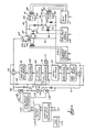
- a modified embodiment, shown in FIGURE 7, provides a means for electronically controlling the effective resistance in series with the x-ray tubes. This is accomplished by replacing adjustable resistors 74 and 75 with high voltage control vacuum tubes 110 and 111. These tubes may be triodes or tetrodes. The use of such tubes allows a more independent choice of techniques for the two pulses since the effective resistance can be changed very quickly.
- a further benefit of using the high voltage control tubes is that dynamic regulation of kVp during each x-ray pulse is made possible for any case where such regulation might be wanted.
- FIGURE 7 the circuitry is the same as in the FIGURE 3 embodiment except for the voltage regulator tubes 110 and 111 and the circuit components between them. Parts which are similar in FIGURE 7 to those in FIGURE 3 are given the same reference numerals.
- a voltage divider circuit comprised of resistors 112, 113 and 114 is connected across the anode 64 and filament or cathode 65 of the x-ray tube.
- Resistor 113 is center-tapped and grounded at 115 consistent with the voltage symmetry of the system which was mentioned earlier.
- the voltage drop across resistor 113 is representative of the voltage drop across the x-ray tube when it is conducting and not conducting.
- This sensed voltage is provided to a comparator 116 for comparison with a reference voltage, corresponding with desired kVp as suggested by the arrowhead line marked 117.
- Control grid bias voltage sources 118 and 119 are provided for altering conductivity of regulator tubes 110 and 111, respectively.
- the regulator tubes illustrated in this example are tetrodes and thus have two control grids.
- Comparator 116 develops an error signal if the voltage drop across the x-ray tube results in a voltage across resistor 113 that leaves difference between that voltage and the reference voltage.
- the error signal is coupled through a pair of opto-isolators 120 and 121, to grid voltage control devices 122 and 123.
- the control devices respond to the error signals by adjusting the grid bias voltage source output in real-time.
- the negative bias voltage on the regulator tube control grids is constantly regulated or adjusted up or down during an x-ray pulse in response to error signals. This results in altering the impedance of the regulator tubes and, hence, maintenance of a constant voltage drop across the x-ray tube.
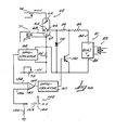
- FIGURE 10 is an alternative system for causing an x-ray tube to emit pulsed beams at any practical energy level, that is, with any desired voltage drop across the tube, and at selected x-ray intensities, that is, with any desired current level through the tube.
- FIGURE 10 parts which are similar to those appearing in FIGURES 3 and 7 are assigned the same reference numerals.
- bias voltage source 81 only one bias voltage source 81 is used. It is supplied with ac through a transformer 82 and includes a rectifier circuit, not shown, which results in a negative dc bias voltage appearing on output line 84 and a positive voltage on line 85. The voltage between output lines 84 and 85 is sufficiently high to cut off current flow through the x-ray 62 when maximum available bias voltage is applied to control electrode 66 of the tube.
- the FIGURE 10 embodiment alters the conductivity of a shunting circuit in a stepwise fashion tp obtain various x-ray tube currents and voltage drops.
- a high voltage transistor group symbolized by the transistor 150, acts as a variable resistance shunt switching device.
- the transistor is operated in its active region. It is connected across bias voltage source output lines 84 and 85 in a shunting loop which includes short circuit current limiting resistor 86.
- the conductivity level of transistor 150 or the voltage drop across it determines the negative bias voltage level on the control element 66 of the x-ray tube with respect to the cathode filament 65.
- the filament is connected to the -HV high voltage source line as in the previously discussed embodiments.
- a diode 151 protects the transistor against reverse voltage if such should occur.
- the base-emitter circuit of the transistor is pulsed or driven correspondingly.
- a variable amplitude and selctable rate pulse generator provides the switching pulses for transistor 150.
- One pair of pulses 152 for example, composed of a low level pulse 153 and a high level pulse 154 in a pulse train is fed through a resistor 155 whose one end is connected to an input 156 of a comparator amplifier 157.
- the comparator has another input for a reference or feedback signal which will be discussed soon.
- the control signal from the output 159 of the comparator is coupled to the base of transistor 150 through an optoisolator 160.
- transistor 150 When there is no input pulse 153 or 154 occurring, that is, with zero volts on comparator input 156, transistor 150 is highly forward biased and fully turned on. This shunts the bias voltage and results in substantially zero voltage on x-ray tube control element 66 relative to the filament. Thus, during the interpulse interval, the current through the x-ray tube and the voltage drop across it will depend on the load line (see FIGURE 8) which has been established by setting the anode circuit resistor values, such as resistors 74 and 75.
- FIGURE 8 Assuming the no load high voltage (+HV) is constant in a given situation, one may see in FIGURE 8 that a variety of x-ray tube currents and voltage drops or anode voltages can be obtained by operating on the proper load line when the bias voltage on the x-ray tube is substantially zero. With zero bias voltage, x-ray tube current will be relatively high and voltage drop across the tube will be relatively low which is desirable for reasons given earlier.
- transistor 150 With a little more positive triggering pulse such as pulse 153 occurring, transistor 150 switches to a lower conductivity level in which case it shunts less of the bias supply 81 voltage and control element 66 becomes more negative relative to filament 65.
- Reference to the characteristic curves in FIGURE 8 shows that, for whatever load line is being used, the x-ray tube voltage drop will be higher (compared to the previous zero bias voltage state) and the x-ray tube current will decrease which is desirable.
- Pulse 154 could have sufficient amplitude to cut off current flow through the x-ray in cases where x-ray pulses at only two energy levels, that is, a low and a higher energy level and respectively high and lower currents or x-ray intensities are required. However, it should be evident that various pulse amplitude steps, higher and lower than trigger pulse 153, could be provided. This could provide many x-ray tube current and voltage drop combinations. Thus, the data representative of images at various x-ray tube energy levels can be obtained within a very short interval and multiple subtractions could be performed to eliminate otherwise confusing background anatomy and to emphasize particular anatomy such as iodine infused blood vessels.
- Dynamic regulation or real-time regulation of the x-ray tube current is also obtained with the FIGURE 10 system by using a feedback circuit.
- This circuit includes a resistor 161 through which the x-ray tube current flows during each pulse. A voltage drop dependent on current amplitude is produced across resistor 161 during a pulse. By means of an optoisolator 162, this voltage is coupled to the reference voltage input 158 of comparator 157.
- the current error is sensed and the trigger pulses from comparator output 159 are modified. This results in a real-time change in the conductivity of transistor 150 and in the bias voltage in a direction that results in nulling the error.
- Shunting or diversion of the bias voltage in FIGURE 10 is accomplished with the variable impedance semiconductor or transistor switch having its collector-emitter circuit connected across the bias source as in a shunt regulator.
- the collector-emitter circuit could be connected in the shunting loop between resistors 86 and 89, for example comparable to a series regulator. The base of the transistor could then have the trigger pulses applied to it.
Landscapes
- Health & Medical Sciences (AREA)
- Life Sciences & Earth Sciences (AREA)
- Medical Informatics (AREA)
- Engineering & Computer Science (AREA)
- General Health & Medical Sciences (AREA)
- Radiology & Medical Imaging (AREA)
- Surgery (AREA)
- Nuclear Medicine, Radiotherapy & Molecular Imaging (AREA)
- Optics & Photonics (AREA)
- Pathology (AREA)
- Physics & Mathematics (AREA)
- Biomedical Technology (AREA)
- Heart & Thoracic Surgery (AREA)
- Molecular Biology (AREA)
- High Energy & Nuclear Physics (AREA)
- Animal Behavior & Ethology (AREA)
- Biophysics (AREA)
- Public Health (AREA)
- Veterinary Medicine (AREA)
- Toxicology (AREA)
- X-Ray Techniques (AREA)
- Apparatus For Radiation Diagnosis (AREA)
Claims (12)
Applications Claiming Priority (2)
| Application Number | Priority Date | Filing Date | Title |
|---|---|---|---|
| US208095 | 1980-11-18 | ||
| US06/208,095 US4361901A (en) | 1980-11-18 | 1980-11-18 | Multiple voltage x-ray switching system |
Publications (3)
| Publication Number | Publication Date |
|---|---|
| EP0052269A1 EP0052269A1 (de) | 1982-05-26 |
| EP0052269B1 true EP0052269B1 (de) | 1985-07-03 |
| EP0052269B2 EP0052269B2 (de) | 1991-02-20 |
Family
ID=22773162
Family Applications (1)
| Application Number | Title | Priority Date | Filing Date |
|---|---|---|---|
| EP81109054A Expired EP0052269B2 (de) | 1980-11-18 | 1981-10-28 | Doppelspannung-Schaltanordnung für eine Röntgenröhre |
Country Status (5)
| Country | Link |
|---|---|
| US (1) | US4361901A (de) |
| EP (1) | EP0052269B2 (de) |
| JP (2) | JPS57111998A (de) |
| DE (1) | DE3171250D1 (de) |
| ES (1) | ES8305998A1 (de) |
Families Citing this family (56)
| Publication number | Priority date | Publication date | Assignee | Title |
|---|---|---|---|---|
| US4481654A (en) * | 1982-09-09 | 1984-11-06 | General Electric Company | X-Ray tube bias supply |
| US4504895A (en) * | 1982-11-03 | 1985-03-12 | General Electric Company | Regulated dc-dc converter using a resonating transformer |
| US4685118A (en) * | 1983-11-10 | 1987-08-04 | Picker International, Inc. | X-ray tube electron beam switching and biasing method and apparatus |
| US4593371A (en) * | 1983-11-14 | 1986-06-03 | General Electric Company | X-ray tube emission current controller |
| US4654770A (en) * | 1983-12-22 | 1987-03-31 | General Electric Company | Current-limit circuit in X-ray generator |
| US4596029A (en) * | 1983-12-22 | 1986-06-17 | General Electric Company | X-ray generator with phase-advance voltage feedback |
| US4601051A (en) * | 1983-12-22 | 1986-07-15 | General Electric Company | Protective circuit for X-ray generator |
| US4597026A (en) * | 1983-12-22 | 1986-06-24 | General Electric Company | Inverter variable dead time for X-ray generator |
| US4589051A (en) * | 1983-12-22 | 1986-05-13 | General Electric Company | Second breakdown protection circuit for X-ray generator inverter |
| US4541106A (en) * | 1984-02-22 | 1985-09-10 | General Electric Company | Dual energy rapid switching imaging system |
| US4559557A (en) * | 1984-06-01 | 1985-12-17 | General Electric Company | Region-of-interest digital subtraction angiography |
| US4744029A (en) * | 1984-08-31 | 1988-05-10 | Bio-Logic Systems Corporation | Brain electrical activity analysis and mapping |
| GB2169180B (en) * | 1984-12-28 | 1988-06-15 | Toshiba Kk | Ct apparatus and operating method therefor |
| GB2181330B (en) * | 1985-09-26 | 1990-05-09 | Toshiba Kk | X-ray inspection apparatus |
| FR2589028B1 (fr) * | 1985-10-18 | 1987-11-20 | Thomson Cgr | Generateur de rayons x |
| US4703496A (en) * | 1985-12-30 | 1987-10-27 | General Electric Company | Automatic x-ray image brightness control |
| US4780897A (en) * | 1986-05-06 | 1988-10-25 | General Electric Company | Dual energy imaging with kinestatic charge detector |
| FR2667723B1 (fr) * | 1990-10-09 | 1992-11-27 | Gen Electric Cgr | Dispositif d'obtention et de commutation de hautes tensions de polarisation d'electrodes de tube a rayons x. |
| US5107187A (en) * | 1990-12-06 | 1992-04-21 | Maxwell Laboratories, Inc. | High voltage protection resistor |
| US5253282A (en) * | 1992-04-27 | 1993-10-12 | Lunar Corporation | System for selective material imaging |
| US6504898B1 (en) * | 2000-04-17 | 2003-01-07 | Mds (Canada) Inc. | Product irradiator for optimizing dose uniformity in products |
| GB2365304A (en) * | 2000-07-22 | 2002-02-13 | X Tek Systems Ltd | A compact X-ray source |
| US7853312B2 (en) * | 2001-06-07 | 2010-12-14 | Varian Medical Systems, Inc. | Seed localization system for use in an ultrasound system and method of using the same |
| US6535572B2 (en) | 2001-06-15 | 2003-03-18 | Ge Medical Systems Global Technology Company, Llc | Methods and apparatus for compensating computed tomographic channel ganging artifacts |
| US7289599B2 (en) * | 2002-10-04 | 2007-10-30 | Varian Medical Systems Technologies, Inc. | Radiation process and apparatus |
| US7627078B2 (en) * | 2002-11-08 | 2009-12-01 | Ge Medical Systems Global Technology Company, Llc | Methods and apparatus for detecting structural, perfusion, and functional abnormalities |
| US7272429B2 (en) * | 2002-11-27 | 2007-09-18 | Ge Medical Systems Global Technology Company, Llc | Methods and apparatus for facilitating a reduction in artifacts |
| US6813333B2 (en) * | 2002-11-27 | 2004-11-02 | Ge Medical Systems Global Technology Company, Llc | Methods and apparatus for detecting structural, perfusion, and functional abnormalities |
| US6891918B2 (en) * | 2002-11-27 | 2005-05-10 | Ge Medical Systems Global Technology Company, Llc | Methods and apparatus for acquiring perfusion data |
| US20040101088A1 (en) * | 2002-11-27 | 2004-05-27 | Sabol John Michael | Methods and apparatus for discriminating multiple contrast agents |
| US7031425B2 (en) * | 2002-11-27 | 2006-04-18 | Ge Medical Systems Global Technology Company, Llc | Methods and apparatus for generating CT scout images |
| US6999549B2 (en) * | 2002-11-27 | 2006-02-14 | Ge Medical Systems Global Technology, Llc | Method and apparatus for quantifying tissue fat content |
| US7110500B2 (en) * | 2003-09-12 | 2006-09-19 | Leek Paul H | Multiple energy x-ray source and inspection apparatus employing same |
| CN101005804A (zh) * | 2004-08-18 | 2007-07-25 | 皇家飞利浦电子股份有限公司 | 用于评估旋转x射线投影的设备 |
| CN100471453C (zh) * | 2005-06-14 | 2009-03-25 | 佳能株式会社 | 放射线成像装置、其控制方法和放射线成像系统 |
| JP5058517B2 (ja) * | 2005-06-14 | 2012-10-24 | キヤノン株式会社 | 放射線撮像装置及びその制御方法並びに放射線撮像システム |
| JP4692326B2 (ja) * | 2006-02-22 | 2011-06-01 | 株式会社島津製作所 | X線撮像装置 |
| JP5604103B2 (ja) * | 2006-08-31 | 2014-10-08 | コーニンクレッカ フィリップス エヌ ヴェ | X線生成システムの電源 |
| JP2008073115A (ja) * | 2006-09-19 | 2008-04-03 | Shimadzu Corp | X線撮影装置 |
| JP4575909B2 (ja) * | 2006-11-22 | 2010-11-04 | ジーイー・メディカル・システムズ・グローバル・テクノロジー・カンパニー・エルエルシー | X線断層撮影装置 |
| JP2009022450A (ja) * | 2007-07-18 | 2009-02-05 | Ge Medical Systems Global Technology Co Llc | X線ct装置および画像作成方法 |
| ITBO20080147A1 (it) * | 2008-03-05 | 2009-09-06 | Micronica S R L | Apparecchiatura radiologica |
| US7844030B2 (en) * | 2008-03-26 | 2010-11-30 | General Electric Company | System and method of fast switching for spectral imaging |
| US7742573B2 (en) * | 2008-10-17 | 2010-06-22 | General Electric Company | Fast switching circuit for x-ray imaging applications |
| JP5144723B2 (ja) * | 2010-07-02 | 2013-02-13 | ジーイー・メディカル・システムズ・グローバル・テクノロジー・カンパニー・エルエルシー | X線断層撮影装置 |
| CN103765996B (zh) | 2011-06-30 | 2016-12-21 | 皇家飞利浦有限公司 | 信号和电力供应传输 |
| US9044186B2 (en) | 2012-06-25 | 2015-06-02 | George W. Ma | Portable dual-energy radiographic X-ray perihpheral bone density and imaging systems and methods |
| US9634625B2 (en) * | 2013-05-28 | 2017-04-25 | Mediatek Inc. | Radio frequency transmitter with extended power range and related radio frequency transmission method |
| US20150264789A1 (en) * | 2014-03-14 | 2015-09-17 | General Electric Company | Methods and systems for controlling voltage switching |
| US10178980B2 (en) * | 2014-06-19 | 2019-01-15 | Analogic Corporation | Radiation sources and detector array for imaging modality |
| CN104302081B (zh) * | 2014-09-24 | 2017-06-16 | 沈阳东软医疗系统有限公司 | 一种ct球管中灯丝电流的控制方法和设备 |
| DE102016222365B3 (de) * | 2016-11-15 | 2018-04-05 | Siemens Healthcare Gmbh | Verfahren, Computerprogrammprodukt, computerlesbares Medium und Vorrichtung zur Erzeugung von Röntgenpulsen bei einer Röntgenbildgebung |
| CN111385952B (zh) * | 2018-12-28 | 2025-06-27 | 同方威视技术股份有限公司 | 分布式x射线光源发射控制装置 |
| US11071506B1 (en) * | 2020-04-28 | 2021-07-27 | Wisconsin Alumni Research Foundation | X-ray imaging device providing enhanced spatial resolution by energy encoding |
| DE102022206833B4 (de) | 2021-09-01 | 2025-06-18 | Siemens Healthineers Ag | Betreiben einer Röntgenröhre |
| US12557202B2 (en) * | 2023-10-10 | 2026-02-17 | GE Precision Healthcare LLC | Strategy for controlling cathode width voltage |
Family Cites Families (14)
| Publication number | Priority date | Publication date | Assignee | Title |
|---|---|---|---|---|
| US3502877A (en) * | 1967-07-07 | 1970-03-24 | Picker Corp | Grid-controlled x-ray tube control system |
| US3633029A (en) * | 1970-10-27 | 1972-01-04 | Cgr Medical Corp | Pulsed x-ray control system with improved film darkening |
| US3783287A (en) * | 1972-05-18 | 1974-01-01 | Picker Corp | Anode current stabilization circuit x-ray tube having stabilizer electrode |
| DE2304427A1 (de) * | 1973-01-30 | 1974-08-08 | Siemens Ag | Roentgendiagnostikeinrichtung mit mitteln zur veraenderung der roentgenroehrenspannung |
| US4104526A (en) * | 1973-04-24 | 1978-08-01 | Albert Richard D | Grid-cathode controlled X-ray tube |
| DE2339758C3 (de) * | 1973-08-06 | 1979-04-19 | Siemens Ag, 1000 Berlin Und 8000 Muenchen | Röntgendiagnostikeinrichtung zur Herstellung eines Transversal-Schichtbildes |
| JPS5197392A (en) * | 1975-02-21 | 1976-08-26 | x senshutsuryokuno seigyohoho | |
| US4007375A (en) * | 1975-07-14 | 1977-02-08 | Albert Richard D | Multi-target X-ray source |
| JPS53990A (en) * | 1976-06-25 | 1978-01-07 | Toshiba Corp | X-ray device for diagnoses |
| US4029963A (en) * | 1976-07-30 | 1977-06-14 | The Board Of Trustees Of Leland Stanford Junior University | X-ray spectral decomposition imaging system |
| JPS5910557B2 (ja) * | 1976-11-15 | 1984-03-09 | 株式会社東芝 | コンピユ−タ断層撮影装置 |
| JPS5817613B2 (ja) * | 1977-04-30 | 1983-04-08 | 株式会社東芝 | X線断層装置 |
| JPS5425189A (en) * | 1977-07-28 | 1979-02-24 | Toshiba Corp | X-ray tomogram diagnosis unit |
| JPS54142989A (en) * | 1978-04-28 | 1979-11-07 | Toshiba Corp | Automatic aging unit |
-
1980
- 1980-11-18 US US06/208,095 patent/US4361901A/en not_active Expired - Lifetime
-
1981
- 1981-10-28 DE DE8181109054T patent/DE3171250D1/de not_active Expired
- 1981-10-28 EP EP81109054A patent/EP0052269B2/de not_active Expired
- 1981-11-17 ES ES507221A patent/ES8305998A1/es not_active Expired
- 1981-11-17 JP JP56183168A patent/JPS57111998A/ja active Pending
-
1989
- 1989-11-20 JP JP1299914A patent/JPH02174836A/ja active Pending
Also Published As
| Publication number | Publication date |
|---|---|
| EP0052269A1 (de) | 1982-05-26 |
| ES507221A0 (es) | 1983-04-16 |
| JPH02174836A (ja) | 1990-07-06 |
| EP0052269B2 (de) | 1991-02-20 |
| DE3171250D1 (en) | 1985-08-08 |
| JPS57111998A (en) | 1982-07-12 |
| US4361901A (en) | 1982-11-30 |
| ES8305998A1 (es) | 1983-04-16 |
Similar Documents
| Publication | Publication Date | Title |
|---|---|---|
| EP0052269B1 (de) | Doppelspannung-Schaltanordnung für eine Röntgenröhre | |
| RU2523827C2 (ru) | Устройство и способ рентгеновского обследования | |
| JP2778835B2 (ja) | X線撮像用途のマルチエネルギー装置 | |
| US7440547B2 (en) | CT scanner | |
| US5125012A (en) | Computer tomography apparatus | |
| EP1119870A1 (de) | Verfahren und vorrichtung zur abtastung mittels röntgenstrahlung | |
| US4311913A (en) | X-Ray tube current control | |
| JP2005261838A (ja) | X線断層撮影装置 | |
| DE10334782A1 (de) | Elektronenquelle und Kabel für Röntgenröhren | |
| US5923721A (en) | Bi-plane x-ray diagnostic apparatus | |
| EP0206156A2 (de) | Bilderzeugungssystem mittels Röntgenstrahlen | |
| Tateno et al. | Low-dosage x-ray imaging system employing flying spot x-ray microbeam (dynamic scanner) | |
| EP0200272A3 (de) | Röntgenuntersuchungsgerät und Verfahren zur Belichtungssteuerung | |
| EP0648466B1 (de) | Apparat zur Erzeugung von Röntgenbildern | |
| US2972681A (en) | Cinefluorographic apparatus | |
| JPS5910557B2 (ja) | コンピユ−タ断層撮影装置 | |
| JPS6351360B2 (de) | ||
| US10531855B2 (en) | X-ray computed tomography apparatus | |
| US7372943B2 (en) | Method for recording projection image | |
| US6111931A (en) | X-ray apparatus operable at different energy supply sources which respectively deliver different average electrical powers per unit of time | |
| US4731803A (en) | Circuit for operating an X-ray tube | |
| US4181857A (en) | X-ray apparatus for a computed tomography scanner | |
| GB2074415A (en) | Computed tomography with selectable image resolution | |
| US4665539A (en) | Method and apparatus for forming tomographic images | |
| US4109151A (en) | Dual filament x-ray tube used in production of fluoroscopic images |
Legal Events
| Date | Code | Title | Description |
|---|---|---|---|
| PUAI | Public reference made under article 153(3) epc to a published international application that has entered the european phase |
Free format text: ORIGINAL CODE: 0009012 |
|
| AK | Designated contracting states |
Designated state(s): DE FR GB NL |
|
| DET | De: translation of patent claims | ||
| 17P | Request for examination filed |
Effective date: 19821113 |
|
| GRAA | (expected) grant |
Free format text: ORIGINAL CODE: 0009210 |
|
| AK | Designated contracting states |
Designated state(s): DE FR GB NL |
|
| REF | Corresponds to: |
Ref document number: 3171250 Country of ref document: DE Date of ref document: 19850808 |
|
| ET | Fr: translation filed | ||
| PLBI | Opposition filed |
Free format text: ORIGINAL CODE: 0009260 |
|
| 26 | Opposition filed |
Opponent name: SIEMENS AKTIENGESELLSCHAFT, BERLIN UND MUENCHEN Effective date: 19860325 |
|
| NLR1 | Nl: opposition has been filed with the epo |
Opponent name: SIEMENS AKTIENGESELLSCHAFT |
|
| PG25 | Lapsed in a contracting state [announced via postgrant information from national office to epo] |
Ref country code: GB Effective date: 19881028 |
|
| PG25 | Lapsed in a contracting state [announced via postgrant information from national office to epo] |
Ref country code: FR Free format text: LAPSE BECAUSE OF NON-PAYMENT OF DUE FEES Effective date: 19890630 |
|
| GBPC | Gb: european patent ceased through non-payment of renewal fee | ||
| REG | Reference to a national code |
Ref country code: FR Ref legal event code: ST |
|
| PUAH | Patent maintained in amended form |
Free format text: ORIGINAL CODE: 0009272 |
|
| STAA | Information on the status of an ep patent application or granted ep patent |
Free format text: STATUS: PATENT MAINTAINED AS AMENDED |
|
| 27A | Patent maintained in amended form |
Effective date: 19910220 |
|
| AK | Designated contracting states |
Kind code of ref document: B2 Designated state(s): DE FR GB NL |
|
| ET3 | Fr: translation filed ** decision concerning opposition | ||
| NLR2 | Nl: decision of opposition | ||
| NLR3 | Nl: receipt of modified translations in the netherlands language after an opposition procedure | ||
| PGFP | Annual fee paid to national office [announced via postgrant information from national office to epo] |
Ref country code: NL Payment date: 19911031 Year of fee payment: 11 |
|
| PGFP | Annual fee paid to national office [announced via postgrant information from national office to epo] |
Ref country code: DE Payment date: 19911101 Year of fee payment: 11 |
|
| PG25 | Lapsed in a contracting state [announced via postgrant information from national office to epo] |
Ref country code: NL Effective date: 19930501 |
|
| NLV4 | Nl: lapsed or anulled due to non-payment of the annual fee | ||
| PG25 | Lapsed in a contracting state [announced via postgrant information from national office to epo] |
Ref country code: DE Effective date: 19930701 |
|
| APAH | Appeal reference modified |
Free format text: ORIGINAL CODE: EPIDOSCREFNO |