EP0052030A1 - Device for collecting a free falling liquid, and its use in a counter-current liquid-gas contacting installation - Google Patents
Device for collecting a free falling liquid, and its use in a counter-current liquid-gas contacting installation Download PDFInfo
- Publication number
- EP0052030A1 EP0052030A1 EP81401609A EP81401609A EP0052030A1 EP 0052030 A1 EP0052030 A1 EP 0052030A1 EP 81401609 A EP81401609 A EP 81401609A EP 81401609 A EP81401609 A EP 81401609A EP 0052030 A1 EP0052030 A1 EP 0052030A1
- Authority
- EP
- European Patent Office
- Prior art keywords
- liquid
- chute
- main chute
- wall
- main
- Prior art date
- Legal status (The legal status is an assumption and is not a legal conclusion. Google has not performed a legal analysis and makes no representation as to the accuracy of the status listed.)
- Granted
Links
Images

Classifications
-
- F—MECHANICAL ENGINEERING; LIGHTING; HEATING; WEAPONS; BLASTING
- F28—HEAT EXCHANGE IN GENERAL
- F28F—DETAILS OF HEAT-EXCHANGE AND HEAT-TRANSFER APPARATUS, OF GENERAL APPLICATION
- F28F25/00—Component parts of trickle coolers
- F28F25/02—Component parts of trickle coolers for distributing, circulating, and accumulating liquid
- F28F25/04—Distributing or accumulator troughs
-
- Y—GENERAL TAGGING OF NEW TECHNOLOGICAL DEVELOPMENTS; GENERAL TAGGING OF CROSS-SECTIONAL TECHNOLOGIES SPANNING OVER SEVERAL SECTIONS OF THE IPC; TECHNICAL SUBJECTS COVERED BY FORMER USPC CROSS-REFERENCE ART COLLECTIONS [XRACs] AND DIGESTS
- Y10—TECHNICAL SUBJECTS COVERED BY FORMER USPC
- Y10S—TECHNICAL SUBJECTS COVERED BY FORMER USPC CROSS-REFERENCE ART COLLECTIONS [XRACs] AND DIGESTS
- Y10S261/00—Gas and liquid contact apparatus
- Y10S261/11—Cooling towers
-
- Y—GENERAL TAGGING OF NEW TECHNOLOGICAL DEVELOPMENTS; GENERAL TAGGING OF CROSS-SECTIONAL TECHNOLOGIES SPANNING OVER SEVERAL SECTIONS OF THE IPC; TECHNICAL SUBJECTS COVERED BY FORMER USPC CROSS-REFERENCE ART COLLECTIONS [XRACs] AND DIGESTS
- Y10—TECHNICAL SUBJECTS COVERED BY FORMER USPC
- Y10S—TECHNICAL SUBJECTS COVERED BY FORMER USPC CROSS-REFERENCE ART COLLECTIONS [XRACs] AND DIGESTS
- Y10S261/00—Gas and liquid contact apparatus
- Y10S261/85—Droplet catchers
Abstract
Description
La présente invention est relative aux installations de mise en contact à contre-courant d'un liquide avec un gaz, notamment celles utilisées pour assurer le refroidissement d'un liquide tel que de l'eau par l'air atmosphérique, et concerne plus spécialement un dispositif pour recueillir un liquide tombant librement sous forme de pluie ou analogue dans de telles installations.The present invention relates to installations for contacting a liquid against a current with a gas, in particular those used for cooling a liquid such as water with atmospheric air, and relates more specifically a device for collecting a liquid falling freely in the form of rain or the like in such installations.
Les installations de mise en contact à contre-courant d'un liquide avec un gaz comprennent généralement une chambre pourvue à sa partie inférieure d'au moins une ouverture d'entrée du gaz et à sa partie supérieure d'au moins une ouverture de sortie du gaz et, à l'intérieur de ladite chambre, un réseau de distribution de liquide, un corps de mise en contact direct du liquide avec le gaz disposé sous le réseau de distribution, et des moyens pour recueillir le liquide qui s'écoule en chute libre sous forme de pluie ou analogue du corps de mise en contact. Ces moyens peuvent être constitués par un bassin prévu à la base de la chambre et dans lequel le liquide tombe directement. Toutefois, un tel bassin a l'inconvénient d'être d'une construction relativement coûteuse, d'engendrer un bruit important dû à l'impact du liquide tombant sur une hauteur importante du corps de mise en contact sur le liquide présent dans le bassin, et de nécessiter une puissance de pompage importante pour recycler directement ou indirectement le liquide du bassin vers le réseau de distribution. Pour tenter de remédier à ces inconvénients, il est déjà connu, notamment par le brevet FR-A n° 876 525, d'utiliser des dispositifs récepteurs de liquide disposés immédiatement sous le corps d'échange et comprenant chacun une paroi réceptrice inclinée sur la verticale qui déverse le liquide recueilli dans une goulotte s'étendant le long du bord inférieur de la paroi, ces dispositifs qui sont disposés parallèlement les uns aux autres et se chevauchent pour empêcher toute chute directe du liquide du corps d'échange vers le bas de la tour, déversent à l'une de leurs extrémités le liquide recueilli dans un collecteur.Installations for contacting a liquid with a gas against the current generally comprise a chamber provided at its lower part with at least one gas inlet opening and at its upper part with at least one outlet opening gas and, inside said chamber, a liquid distribution network, a body for bringing the liquid into direct contact with the gas placed under the distribution network, and means for collecting the liquid which flows in free fall in the form of rain or the like of the contacting body. These means can be constituted by a basin provided at the base of the chamber and into which the liquid falls directly. However, such a basin has the drawback of being a relatively expensive construction, of generating a significant noise due to the impact of the liquid falling over a significant height of the contacting body on the liquid present in the basin. , and to require a significant pumping power to directly or indirectly recycle the liquid from the basin to the distribution network. In an attempt to remedy these drawbacks, it is already known, in particular from patent FR-A No. 876,525, to use liquid receiving devices placed immediately under the exchange body and each comprising a receiving wall inclined on the vertical which pours the liquid collected in a chute extending along the lower edge of the wall, these devices which are arranged parallel to each other and overlap to prevent any direct fall of the liquid from the exchange body down the tower, pour at one of their ends the liquid collected in a collector.
Cependant, avec ces dispositifs récepteurs de la technique antérieure, on observe un mauvais écoulement du liquide dans les goulottes. Ceci a conduit généralement à prévoir des collecteurs secondaires pour empêcher l'engorgement des goulottes. Ceci ne constitue pas toutefois une solution très satisfaisante.However, with these prior art receiving devices, poor liquid flow is observed in the troughs. This generally led to the provision of secondary collectors to prevent the clogging of the chutes. However, this is not a very satisfactory solution.
La présente invention a pour but d'améliorer l'écoulement du liquide dans les goulottes et est basée sur la constatation du fait que ce mauvais écoulement est dû aux perturbations importantes qui sont créées par la chute du liquide provenant des parois inclinées et pénétrant dans le flot de liquide s'écoulant dans les goulottes.The aim of the present invention is to improve the flow of liquid in the chutes and is based on the observation that this poor flow is due to the significant disturbances which are created by the fall of the liquid coming from the inclined walls and entering the flow of liquid flowing in the chutes.
A cet effet, la présente invention a pour objet un dispositif pour recueillir un liquide tombant librement sous forme de pluie ou analogue, du type comprenant une paroi inclinée sur la verticale et une goulotte, dite ci-après goulotte principale, s'étendant le long du bord inférieur de la parole caractérisé en ce qu'il comprend, sur le trajet du liquide recueilli par la paroi inclinée, et avant son entrée dans la goulotte principale, des moyens pour réduire notablement ou annuler la composante de vitesse verticale du liquide à son entrée dans la goulotte.To this end, the subject of the present invention is a device for collecting a liquid falling freely in the form of rain or the like, of the type comprising a wall inclined to the vertical and a chute, hereinafter called main chute, extending along of the lower edge of the floor, characterized in that it comprises, on the path of the liquid collected by the inclined wall, and before it enters the main chute, means for significantly reducing or canceling the vertical speed component of the liquid at its entry into the chute.
Selon un premier mode de réalisation, les moyens pour réduire notablement ou annuler la composante de vitesse verticale du liquide comprennent des surfaces déflectrices qui confèrent au liquide à son entrée dans la goulotte principale une composante de vitesse notable dans la direction d'écoulement du liquide dans la goulotte principale.According to a first embodiment, the means for appreciably reducing or canceling the vertical speed component of the liquid comprise deflecting surfaces which give the liquid as it enters the main chute a significant speed component in the direction of flow of the liquid in the main chute.
Ces surfaces déflectrices peuvent être, par exemple, constituées par des petites goulottes inclinées ou des godets intermédiaires disposés à l'entrée de la goulotte principale, qui confèrent au liquide une direction voisine de celle de l'écoulement du liquide dans la goulotte principale. Ces surface déflectrices peuvent également être constituées par des nervures disposées sur la paroi inclinée, selon la ligne de plus grande pente, et dont la partie inférieure est incurvée dans la direction de l'écoulement du liquide dans la goulotte principale ou encore par des nervures disposées sur la paroi inclinée et elles-mêmes inclinées dans la direction de l'écoulement du liquide dans la goulotte principale. De telles surfaces déflectrices font subir au liquide un changement de direction dans le sens de l'écoulement dans la goulotte principale et lui confèrent une vitesse qui peut être supérieure à celle du liquide dans la goulotte principale. On diminue ainsi les perturbations dans l'écoulement, mais on accélère également l'écoulement du liquide dans la goulotte principale.These deflecting surfaces can be, for example, constituted by small inclined troughs or intermediate buckets arranged at the inlet of the main chute, which give the liquid a direction close to that of the flow of the liquid in the main chute. These deflecting surfaces can also be constituted by ribs arranged on the inclined wall, along the line of greatest slope, and the lower part of which is curved in the direction of the flow of the liquid in the main chute or even by ribs arranged on the inclined wall and themselves inclined in the direction of the flow of the liquid in the main chute. Such deflecting surfaces subject the liquid to a change of direction in the direction of flow in the main chute and give it a speed which may be greater than that of the liquid in the main chute. This decreases the disturbances in the flow, but also accelerates the flow of the liquid in the main chute.
Selon un autre mode de réalisation, les moyens pour réduire ou annuler la composante de vitesse verticale comprennent un ou des obstacles tendant à annuler la vitesse du liquide à son entrée dans la goulotte principale.According to another embodiment, the means for reducing or canceling the vertical speed component comprise one or more obstacles tending to cancel the speed of the liquid as it enters the main chute.
On a constaté, en effet, qu'il°n'est pas nécessaire pour améliorer l'écoulement de conférer au liquide entrant dans la goulotte principale une composante de vitesse dans la direction de l'écoulement dans la goulotte principale mais qu'il suffit de réduire notablement ou d'annuler la composante de vitesse verticale et, à cet effet, la solution la plus simple consiste à réduire ou annuler purement et simplement la vitesse du liquide avant son entrée dans la goulotte principale.It has been found, in fact, it is not necessary ° to improve the flow of imparting to the liquid entering the main trough a velocity component in the direction of flow in the main channel but it suffices to significantly reduce or cancel the vertical speed component and, for this purpose, the simplest solution consists in purely or simply reducing or canceling the speed of the liquid before it enters the main chute.
Les obstacles peuvent être par exemple constitués par des tétons disposés sur la paroi inclinée, une nervure parallèle à la goulotte principale et disposée à l'entrée de cette dernière, ou mieux par une grille à mailles fines recouvrant la goulotte principale.The obstacles may for example be constituted by pins arranged on the inclined wall, a rib parallel to the main chute and arranged at the entrance to the latter, or better still by a fine mesh grid covering the main chute.
On peut également combiner les deux modes de réalisation et utiliser des petites goulottes inclinées constituées par des grilles à mailles fines.It is also possible to combine the two embodiments and use small inclined chutes formed by fine mesh grids.
L'invention a également pour objet une installation de mise en contact à contre-courant d'un liquide avec un gaz comprenant une chambre pourvue à sa partie inférieure d'au moins une ouverture d'entrée du gaz et à sa partie supérieure d'au moins une ouverture de sortie du gaz et, à l'intérieur de ladite chambre, un réseau de distribution de liquide, un corps de mise en contact direct du liquide avec le gaz disposé sous le réseau de distribution, et des dispositifs récepteurs de liquide tels que définis ci-dessus disposés sous ledit corps pour receuil- lir le liquide qui s'en écoule.The invention also relates to an installation for contacting a liquid with a gas against the current, comprising a chamber provided at its lower part with at least one gas inlet opening and at its upper part with at least one gas outlet opening and, inside said chamber, a liquid distribution network, a body for bringing the liquid into direct contact with the gas disposed under the distribution network, and liquid receiving devices as defined above arranged under said body to collect the liquid which flows therefrom.
D'autres caractéristiques et avantages de l'invention ressortiront de la description qui va suivre, faite en se référant aux dessins annexés donnés uniquement à titre d'exemple et sur lesquels :
- les Fig. 1 à 9 sont des vues en perspective de différents modes de réalisation de l'invention.
- Figs. 1 to 9 are perspective views of different embodiments of the invention.
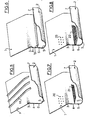
Les dispositifs pour recueillir un liquide tombant librement sous forme de pluie représentés sur les Fig. 1 à 9 comprennent, de manière connue, une paroi 1 inclinée sur la verticale et une goulotte 2 dite goulotte principale s'étendant le long du bord inférieur de la paroi inclinée 1. La paroi inclinée 1 qui est plane se raccorde à la goulotte 2 par une partie arrondie 3 qui se prolonge vers le bas, en direction de la goulotte, par une courte partie verticale 4. La goulotte 2 présente un fond arrondi 5 et deux bords verticaux 6 et 7 de part et d'autre, dont l'un, le bord 6, est dans le prolongement de la partie verticale 4.The devices for collecting a freely falling liquid in the form of rain represented in FIGS. 1 to 9 comprise, in known manner, a
Le dispositif représenté sur la Fig. 1 comprend une succession horizontale de petites goulottes inclinées 8 disposées bout à bout sur la partie verticale 4. Chaque petite goulotte inclinée 8 comprend un fond plat 9 fixé sur la partie verticale 4 et fortement incliné par rapport à la verticale et un bord vertical 10 qui est prolongé par une bande 11 horizontale inclinée vers l'extérieur de la petite goulotte inclinée 8. Les parties hautes des bords 10, ainsi que les bandes 11 des petites goulottes inclinées successives sont fixées entre elles.The device shown in FIG. 1 comprises a horizontal succession of small
Le liquide qui ruisselle sur la paroi inclinée 1 est dévié au niveau de la partie verticale 4 par le fond 9 de chaque petite goulotte inclinée 8 parallèlement à ce fond. Il sort de chaque petite goulotte inclinée 8 en ayant une composante de vitesse verticale nettement réduite et pénètre dans la goulotte principale 2 dans la direction de l'écoulement du liquide dans cette goulotte.The liquid flowing on the
Le dispositif représenté sur la Fig: 2 est très semblable à celui de la Fig. 1 dont il ne diffère que par la forme des petites goulottes inclinées. Chaque petite goulotte inclinée 12 est constituée d'un demi tronc de cône dont la petite base 13 est fermée et la grande base est ouverte. Chaque petite goulotte inclinée est fixée à la partie 4 par l'un de ses bords supérieurs 14 disposés horizontalement. Comme pour le dispositif représenté sur la Fig. 1, le liquide est dévié par le fond de chaque petite goulotte inclinée 12, parallèlement à ce fond et sort de chaque petite goulotte inclinée par la grande base du tronc de cône, en ayant une composante de vitesse verticale nettement réduite.The device shown in FIG: 2 is very similar to that of FIG. 1 from which it differs only in the shape of the small inclined chutes. Each small
Le dispositif représenté sur la Fig. 3 comprend une succession horizontale de godets 15 disposés sur la partie verticale 4 et qui sont constitués chacun par un quart de sphère. Chaque godet 15 dévie le liquide qui ruisselle sur la paroi 1 et l'envoie dans la goulotte 2 avec une composante de vitesse verticale pratiquement annulée.The device shown in FIG. 3 comprises a horizontal succession of
Le dispositif représenté sur la Fig. 4 comprend une succession de nervures 16 disposées sur la paroi inclinée 1 selon la ligne de plus grande pente. La partie inférieure 17 de chacune de ces nervures au niveau de la partie arrondie 3 est incurvée dans la direction de l'écoulement du liquide dans la goulotte 2 et dévie le liquide ruisselant sur la paroi 1 dans la direction de l'écoulement du liquide dans cette goulotte 2.The device shown in FIG. 4 comprises a succession of
Le dispositif représenté sur la Fig. 5 comprend une succession de nervures 18 disposées sur la paroi 1 jusqu'à l'entrée de la goulotte 2 et inclinées dans la direction de l'écoulement du liquide dans la goulotte 2. Grâce à ces nervures, le liquide ruisselant sur la paroi 1 reçoit une composante de vitesse dans la direction de l'écoulement du liquide dans la goulotte 2.The device shown in FIG. 5 includes a succession of ribs 18 arranged on the
Le dispositif représenté sur la Fig. 6 comprend une nervure 19 parallèle à la goulotte principale 2 et disposée à l'entrée de cette dernière sur le bord vertical 6. Cette nervure a pour effet de "briser" l'écoulement du liquide ruisselant sur la paroi inclinée 1 quand il arrive dans la goulotte 2.The device shown in FIG. 6 comprises a
Le dispositif représenté sur la Fig. 7 comprend, d'une part, des tétons 20 faisant saillie sur la paroi inclinée destinés à ralentir le liquide ruisselant sur cette paroi et, d'autre part, une grille 21 à mailles fines constituées par un treillis de fils métalliques et recouvrant la goulotte 2. Cette grille 21 a, comme la nervure 19, pour effet de "briser" l'écoulement du liquide de façon à annuler pratiquement la vitesse du liquide quand il arrive dans la goulotte 2.The device shown in FIG. 7 comprises, on the one hand, nipples 20 projecting from the inclined wall intended to slow down the liquid flowing on this wall and, on the other hand, a
Le dispositif représenté sur la Fig. 8 est une variante de la Fig. 7;et comprend, à la place de la grille à fils métalliques une grille 22 constituée par une plaque pourvue de canaux verticaux.The device shown in FIG. 8 is a variant of FIG. 7; and comprises, in place of the grid with metallic wires, a
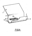
Enfin, le dispositif représenté sur la Fig. 9 est une combinaison des dispositifs représentés aux Fig. 2 et 7 et comprend une succession de petites goulottes inclinées 23 en forme de demi troncs de cône constituées par un treillis de fils métalliques qui, à la fois, annulent pratiquement la vitesse du liquide qui les traverse et dévient l'excédent du liquide dans la direction de l'écoulement du liquide dans la goulotte 2.Finally, the device shown in FIG. 9 is a combination of the devices shown in FIGS. 2 and 7 and comprises a succession of small
Claims (11)
Priority Applications (1)
| Application Number | Priority Date | Filing Date | Title |
|---|---|---|---|
| AT81401609T ATE3084T1 (en) | 1980-11-12 | 1981-10-15 | DEVICE FOR COLLECTING A FREE-FALLING LIQUID AND ITS APPLICATION IN A LIQUID-GAS COUNTER-CURRENT CONTACT DEVICE |
Applications Claiming Priority (2)
| Application Number | Priority Date | Filing Date | Title |
|---|---|---|---|
| FR8024018A FR2493718A1 (en) | 1980-11-12 | 1980-11-12 | DEVICE FOR COLLECTING A FLOWING FALLING FLUID AND ITS APPLICATION TO AN INSTALLATION FOR CONTRA-CURRENT CONTACTING A LIQUID WITH A GAS |
| FR8024018 | 1980-11-12 |
Publications (2)
| Publication Number | Publication Date |
|---|---|
| EP0052030A1 true EP0052030A1 (en) | 1982-05-19 |
| EP0052030B1 EP0052030B1 (en) | 1983-04-13 |
Family
ID=9247880
Family Applications (1)
| Application Number | Title | Priority Date | Filing Date |
|---|---|---|---|
| EP81401609A Expired EP0052030B1 (en) | 1980-11-12 | 1981-10-15 | Device for collecting a free falling liquid, and its use in a counter-current liquid-gas contacting installation |
Country Status (5)
| Country | Link |
|---|---|
| US (2) | US4385010A (en) |
| EP (1) | EP0052030B1 (en) |
| AT (1) | ATE3084T1 (en) |
| DE (1) | DE3160185D1 (en) |
| FR (1) | FR2493718A1 (en) |
Cited By (3)
| Publication number | Priority date | Publication date | Assignee | Title |
|---|---|---|---|---|
| EP0162993A1 (en) * | 1984-05-29 | 1985-12-04 | GEA Luftkühlergesellschaft Happel GmbH & Co. | Wet or combined wet-dry cooling tower |
| EP2676738A1 (en) * | 2012-06-19 | 2013-12-25 | General Electric Company | Module for a device generating at least one water curtain and corresponding device |
| US9050479B2 (en) | 2011-11-30 | 2015-06-09 | General Electric Company | Module for a device generating at least one water curtain and corresponding device |
Families Citing this family (36)
| Publication number | Priority date | Publication date | Assignee | Title |
|---|---|---|---|---|
| FI65468C (en) * | 1981-06-02 | 1984-05-10 | Kontekla Oy | TAKBRUNN ELLER LIKNANDE FOER EN BYGGNAD |
| CH664591A5 (en) * | 1982-03-09 | 1988-03-15 | Kontekla Oy | APPARATUS FOR DRAINING WATER FROM THE ROOF. |
| FR2529655B1 (en) * | 1982-07-01 | 1986-05-16 | Hamon | RUNOFF ATMOSPHERIC REFRIGERATOR COMPRISING CHUTS |
| US5170597A (en) * | 1992-04-27 | 1992-12-15 | Stearns Carl D | Roof flashing with improved drip guard |
| US5487849A (en) * | 1993-12-03 | 1996-01-30 | Tower Tech, Inc. | Pultruded cooling tower construction |
| CN1090525C (en) * | 1993-12-03 | 2002-09-11 | 托尔技术有限公司 | Dual layered drainage collection system |
| US5545356A (en) * | 1994-11-30 | 1996-08-13 | Tower Tech, Inc. | Industrial cooling tower |
| US5529365A (en) * | 1995-02-24 | 1996-06-25 | Saunders; Charles A. | Trim edging for motorcycle fairing |
| US5653068A (en) * | 1996-04-29 | 1997-08-05 | Moody; Ben A. | Water diverting strip |
| US5953861A (en) * | 1997-04-21 | 1999-09-21 | Podgwaite; Frank C. | Roof freeze protection apparatus and method |
| US5958306A (en) * | 1997-10-16 | 1999-09-28 | Curtis; Harold D. | Pre-collectors for cooling towers |
| US6151836A (en) * | 1997-10-30 | 2000-11-28 | Mcglothlin; W. Neal | Gutter system |
| US6527258B2 (en) * | 1999-03-19 | 2003-03-04 | Sulzer Chemtech Ag | Apparatus for the collection and distribution of liquid in a column |
| US6089188A (en) * | 1999-04-26 | 2000-07-18 | Corley; Mary Elizabeth | Animal spraying and scratching property protector |
| US6758463B2 (en) * | 2001-11-21 | 2004-07-06 | Air Products And Chemicals, Inc. | Liquid distributor internal baffling |
| US7100331B2 (en) * | 2002-06-03 | 2006-09-05 | Walter Wayne Nehring | Directional flow flashing |
| CN100364648C (en) * | 2002-11-22 | 2008-01-30 | 弗劳尔公司 | Configurations and methods for ribbed downcomer wall |
| CN100364632C (en) * | 2003-04-07 | 2008-01-30 | 科克-格利奇有限公司 | Combined liquid collector and mixer for mass transfer column |
| US7125004B2 (en) * | 2003-12-15 | 2006-10-24 | Koch-Glitsch, Lp | Liquid distributor for use in mass transfer column |
| US9463397B2 (en) * | 2008-04-04 | 2016-10-11 | Gtc Technology Us Llc | System and method for liquid distribution |
| BRPI1006288A2 (en) * | 2009-03-03 | 2016-04-19 | Harold Dean Curtis | direct draft fluid cooler, water collection device and compact cooling tower |
| US20150330710A1 (en) * | 2009-03-03 | 2015-11-19 | Harold D. Curtis Revocable Trust | Direct Forced Draft Fluid Cooling Tower |
| WO2011009048A1 (en) * | 2009-07-17 | 2011-01-20 | Acs Industries, Inc. | Enhanced capacity, reduced turbulence, trough-type liquid collector trays |
| CA2689266A1 (en) * | 2009-12-23 | 2011-06-23 | Aker Solutions Canada Inc. | Improved distributor |
| CN103234380B (en) * | 2013-04-19 | 2016-03-09 | 国核电力规划设计研究院 | A kind of captation of cooling tower and method |
| EP3069094B1 (en) * | 2013-11-12 | 2019-01-16 | Stellenbosch University | Water collection trough assembly |
| US10107001B2 (en) | 2014-03-28 | 2018-10-23 | Syntech Towers, L.L.C. | CMU cooling tower and method of construction |
| US9612034B1 (en) * | 2015-11-04 | 2017-04-04 | Zdislav David Lasevski | Air conditioner water drop noise blocker |
| CN106931610B (en) * | 2015-12-28 | 2020-09-08 | 夏普株式会社 | Water supply device, humidifier and purifier including the same |
| CN106091795B (en) * | 2016-06-21 | 2019-05-07 | 四川中乙制冷设备有限公司 | Fan-free energy-saving cooling tower high-efficient water-recovering device |
| US10844604B2 (en) | 2017-06-06 | 2020-11-24 | Roofers Advantage Products, LLC | Field shingle layout marks on roof drip edge |
| US10852079B2 (en) | 2017-07-24 | 2020-12-01 | Harold D. Curtis | Apparatus for cooling liquid and collection assembly therefor |
| CN109186314A (en) * | 2018-10-29 | 2019-01-11 | 赵金海 | A kind of bottom blast device used for cooling tower |
| KR102077521B1 (en) * | 2019-02-18 | 2020-02-19 | 주식회사 오티티 | A cooling tower in which a filler is formed in multiple stages and a cooling water mixing section is provided between the fillers |
| US11609051B2 (en) | 2020-04-13 | 2023-03-21 | Harold D. Revocable Trust | Apparatus for cooling liquid and collection assembly therefor |
| CN111750724B (en) * | 2020-06-18 | 2021-04-20 | 上海交通大学 | Passive pulse type water flow adjusting device for water flow cooling |
Citations (5)
| Publication number | Priority date | Publication date | Assignee | Title |
|---|---|---|---|---|
| GB1047454A (en) * | 1900-01-01 | |||
| GB734185A (en) * | 1951-03-27 | 1955-07-27 | Samuel Couzin | Improvements in installations for contacting liquids and gases particularly applicable to water cooling towers |
| CH451216A (en) * | 1966-09-07 | 1968-05-15 | Balcke Ag Maschbau | Device for reducing the water noise in cooling towers |
| DE2250776A1 (en) * | 1972-10-17 | 1974-04-18 | Schoell Guenter | PROCESS AND DEVICES TO REDUCE PUMP WORK FOR THE COOLING WATER CIRCUIT IN WET COOLING TUBES |
| FR2407449A1 (en) * | 1977-10-26 | 1979-05-25 | Hamon | DEVICE FOR COLLECTING A FREE DROPPING LIQUID AND ITS APPLICATION TO A PLANT FOR CONTACT OF A LIQUID WITH A GAS |
Family Cites Families (10)
| Publication number | Priority date | Publication date | Assignee | Title |
|---|---|---|---|---|
| US883632A (en) * | 1907-06-13 | 1908-03-31 | William Feyler | Eaves-trough and fastening therefor. |
| US1647281A (en) * | 1926-04-01 | 1927-11-01 | Frank M Doyle | Cooling tower |
| US2209741A (en) * | 1939-02-17 | 1940-07-30 | Leo E Sullivan | Roofing gutter and guard therefor |
| US2288121A (en) * | 1940-08-04 | 1942-06-30 | American Steel & Wire Co | Protector for eave troughs |
| US2626129A (en) * | 1950-02-24 | 1953-01-20 | Ind Manufacturers Ltd | Liquid distributor for cooling apparatus |
| US2669950A (en) * | 1952-10-08 | 1954-02-23 | George A Bartholomew | Nonclogging eaves structure |
| US3081987A (en) * | 1959-07-13 | 1963-03-19 | George W Meek | Cooling towers |
| FR1351499A (en) * | 1962-12-20 | 1964-02-07 | Improvements to liquid cooling devices | |
| DE1484382B1 (en) * | 1964-02-18 | 1969-11-20 | Uhl & Moos Betonwaren Und Baus | Set of components made of concrete for the production of weft channels |
| US3611731A (en) * | 1968-12-27 | 1971-10-12 | Plastiers Ltd | Gutters and gutter fittings |
-
1980
- 1980-11-12 FR FR8024018A patent/FR2493718A1/en active Granted
-
1981
- 1981-10-15 DE DE8181401609T patent/DE3160185D1/en not_active Expired
- 1981-10-15 EP EP81401609A patent/EP0052030B1/en not_active Expired
- 1981-10-15 AT AT81401609T patent/ATE3084T1/en not_active IP Right Cessation
- 1981-11-09 US US06/319,372 patent/US4385010A/en not_active Expired - Fee Related
-
1983
- 1983-01-03 US US06/455,253 patent/US4416835A/en not_active Expired - Fee Related
Patent Citations (5)
| Publication number | Priority date | Publication date | Assignee | Title |
|---|---|---|---|---|
| GB1047454A (en) * | 1900-01-01 | |||
| GB734185A (en) * | 1951-03-27 | 1955-07-27 | Samuel Couzin | Improvements in installations for contacting liquids and gases particularly applicable to water cooling towers |
| CH451216A (en) * | 1966-09-07 | 1968-05-15 | Balcke Ag Maschbau | Device for reducing the water noise in cooling towers |
| DE2250776A1 (en) * | 1972-10-17 | 1974-04-18 | Schoell Guenter | PROCESS AND DEVICES TO REDUCE PUMP WORK FOR THE COOLING WATER CIRCUIT IN WET COOLING TUBES |
| FR2407449A1 (en) * | 1977-10-26 | 1979-05-25 | Hamon | DEVICE FOR COLLECTING A FREE DROPPING LIQUID AND ITS APPLICATION TO A PLANT FOR CONTACT OF A LIQUID WITH A GAS |
Cited By (3)
| Publication number | Priority date | Publication date | Assignee | Title |
|---|---|---|---|---|
| EP0162993A1 (en) * | 1984-05-29 | 1985-12-04 | GEA Luftkühlergesellschaft Happel GmbH & Co. | Wet or combined wet-dry cooling tower |
| US9050479B2 (en) | 2011-11-30 | 2015-06-09 | General Electric Company | Module for a device generating at least one water curtain and corresponding device |
| EP2676738A1 (en) * | 2012-06-19 | 2013-12-25 | General Electric Company | Module for a device generating at least one water curtain and corresponding device |
Also Published As
| Publication number | Publication date |
|---|---|
| ATE3084T1 (en) | 1983-04-15 |
| US4385010A (en) | 1983-05-24 |
| FR2493718A1 (en) | 1982-05-14 |
| FR2493718B1 (en) | 1982-12-10 |
| EP0052030B1 (en) | 1983-04-13 |
| US4416835A (en) | 1983-11-22 |
| DE3160185D1 (en) | 1983-05-19 |
Similar Documents
| Publication | Publication Date | Title |
|---|---|---|
| EP0052030B1 (en) | Device for collecting a free falling liquid, and its use in a counter-current liquid-gas contacting installation | |
| FR2558247A1 (en) | DRIP COLLECTOR ASSEMBLY AND LIQUID COLLECTION TRAY FOR COOLING TOWER | |
| FR2553826A1 (en) | MOTOR VEHICLE, ESPECIALLY A CAR, HAVING AT LEAST TWO RADIATORS WITH SEPARATE AIR CONDUITS | |
| FR2982286A1 (en) | ANTI-DROP GUARD LAME FOR PROTECTION ROOF | |
| EP0017517A2 (en) | Channelling device for mixing dry and wet streams of atmospheric air parallel stream refrigerant | |
| FR2669000A1 (en) | DEVICE FOR COLLECTING AND TURNING THE RAINWATER PROJECTED UPWARD BY A VEHICLE WHEEL. | |
| EP1034337B1 (en) | Water draining device | |
| EP0891461A1 (en) | Device for draining rainwater from the roof surface of a building | |
| FR2465166A1 (en) | DEVICE FOR DISTRIBUTING AIR, ESPECIALLY FOR AIR SURSATURE | |
| EP3329068A2 (en) | The invention relates to dynamic artificial wave installations for surfing | |
| FR2670718A1 (en) | FRESH AIR SUCTION CHANNEL FOR A MOTOR VEHICLE. | |
| FR3017633A1 (en) | DEVICE FOR DESCENTING AND DRAINING RAINWATER WATER OUT OF A ROOF GUTTER OF A CONSTRUCTION | |
| FR2982287A1 (en) | MOUNTING RAIL FOR EQUIPMENT EQUIPPED WITH AN ORIENTABLE BLADE INSTALLATION FORMING A PROTECTION ROOF | |
| FR2484072A1 (en) | DEVICE FOR WATERING RUNOFF PLATES WITH COOLING WATER TO BE COOLED | |
| FR2702235A1 (en) | Raised receiver for sewer lines, with storm water outlet, overflow opening and discharge valve | |
| FR2938213A1 (en) | Motor vehicle front part, has mechanical units implanted on two vertical and transversal walls of parallelepiped case for reducing amplitude of undulations of rain water accumulated at bottom surface of cowl | |
| FR3140497A1 (en) | System comprising a photovoltaic panel and a rainwater distributor | |
| FR2675171A1 (en) | Device for the recovery of rainwater | |
| FR2597361A1 (en) | Device for collecting a liquid in a plant for bringing a liquid into contact with a gas | |
| EP1524370B1 (en) | Sequenced waste water feeder for use in waste water treatment plants | |
| FR3059623A1 (en) | ANCHORING DEVICE FOR A VEHICLE WITH A DEFLECTIVE HOOD FOR PROTECTION AGAINST RUNOFF WATERS, IN PARTICULAR FROM A WIPER DRIVING DRIVE | |
| EP0626485A1 (en) | Drainage device for rainwater | |
| FR2467359A1 (en) | Natural circulation extraction ventilator for flat roof - covers horizontal or slightly inclined roof openings with baffles to deflect air flow | |
| EP2806081B1 (en) | Water box | |
| EP1213235B1 (en) | Discharge means for a silo |
Legal Events
| Date | Code | Title | Description |
|---|---|---|---|
| PUAI | Public reference made under article 153(3) epc to a published international application that has entered the european phase |
Free format text: ORIGINAL CODE: 0009012 |
|
| AK | Designated contracting states |
Designated state(s): AT BE CH DE FR GB IT LU NL SE |
|
| 17P | Request for examination filed |
Effective date: 19820413 |
|
| ITF | It: translation for a ep patent filed |
Owner name: FUMERO BREVETTI S.N.C. |
|
| GRAA | (expected) grant |
Free format text: ORIGINAL CODE: 0009210 |
|
| AK | Designated contracting states |
Designated state(s): AT BE CH DE FR GB IT LI LU NL SE |
|
| REF | Corresponds to: |
Ref document number: 3084 Country of ref document: AT Date of ref document: 19830415 Kind code of ref document: T |
|
| REF | Corresponds to: |
Ref document number: 3160185 Country of ref document: DE Date of ref document: 19830519 |
|
| PGFP | Annual fee paid to national office [announced via postgrant information from national office to epo] |
Ref country code: LU Payment date: 19831019 Year of fee payment: 3 |
|
| PG25 | Lapsed in a contracting state [announced via postgrant information from national office to epo] |
Ref country code: LU Free format text: LAPSE BECAUSE OF NON-PAYMENT OF DUE FEES Effective date: 19831031 |
|
| PLBI | Opposition filed |
Free format text: ORIGINAL CODE: 0009260 |
|
| 26 | Opposition filed |
Opponent name: GEA KUEHLTURMBAU UND LUFTKONDENSATION GMBH Effective date: 19831121 |
|
| PGFP | Annual fee paid to national office [announced via postgrant information from national office to epo] |
Ref country code: DE Payment date: 19840925 Year of fee payment: 4 |
|
| PGFP | Annual fee paid to national office [announced via postgrant information from national office to epo] |
Ref country code: SE Payment date: 19840930 Year of fee payment: 4 |
|
| PGFP | Annual fee paid to national office [announced via postgrant information from national office to epo] |
Ref country code: CH Payment date: 19841004 Year of fee payment: 4 |
|
| PLBN | Opposition rejected |
Free format text: ORIGINAL CODE: 0009273 |
|
| STAA | Information on the status of an ep patent application or granted ep patent |
Free format text: STATUS: OPPOSITION REJECTED |
|
| 27O | Opposition rejected |
Effective date: 19850301 |
|
| NLR2 | Nl: decision of opposition | ||
| PGFP | Annual fee paid to national office [announced via postgrant information from national office to epo] |
Ref country code: AT Payment date: 19860922 Year of fee payment: 6 |
|
| PGFP | Annual fee paid to national office [announced via postgrant information from national office to epo] |
Ref country code: NL Payment date: 19871031 Year of fee payment: 7 |
|
| PG25 | Lapsed in a contracting state [announced via postgrant information from national office to epo] |
Ref country code: AT Effective date: 19881015 Ref country code: GB Effective date: 19881015 |
|
| PG25 | Lapsed in a contracting state [announced via postgrant information from national office to epo] |
Ref country code: SE Effective date: 19881016 |
|
| PG25 | Lapsed in a contracting state [announced via postgrant information from national office to epo] |
Ref country code: CH Effective date: 19881031 Ref country code: LI Effective date: 19881031 |
|
| PG25 | Lapsed in a contracting state [announced via postgrant information from national office to epo] |
Ref country code: NL Effective date: 19890501 |
|
| NLV4 | Nl: lapsed or anulled due to non-payment of the annual fee | ||
| REG | Reference to a national code |
Ref country code: CH Ref legal event code: PL |
|
| PG25 | Lapsed in a contracting state [announced via postgrant information from national office to epo] |
Ref country code: DE Effective date: 19890701 |
|
| GBPC | Gb: european patent ceased through non-payment of renewal fee | ||
| ITTA | It: last paid annual fee | ||
| PGFP | Annual fee paid to national office [announced via postgrant information from national office to epo] |
Ref country code: BE Payment date: 19911113 Year of fee payment: 11 |
|
| PG25 | Lapsed in a contracting state [announced via postgrant information from national office to epo] |
Ref country code: BE Effective date: 19921031 |
|
| BERE | Be: lapsed |
Owner name: HAMON-SOBELCO S.A. Effective date: 19921031 |
|
| EUG | Se: european patent has lapsed |
Ref document number: 81401609.3 Effective date: 19890509 |
|
| PGFP | Annual fee paid to national office [announced via postgrant information from national office to epo] |
Ref country code: FR Payment date: 19980928 Year of fee payment: 18 |
|
| PG25 | Lapsed in a contracting state [announced via postgrant information from national office to epo] |
Ref country code: FR Free format text: LAPSE BECAUSE OF NON-PAYMENT OF DUE FEES Effective date: 20000630 |
|
| REG | Reference to a national code |
Ref country code: FR Ref legal event code: ST |