EP0051515B1 - Rotationsservogetriebe, insbesondere für Fahrzeuglenkungen - Google Patents
Rotationsservogetriebe, insbesondere für Fahrzeuglenkungen Download PDFInfo
- Publication number
- EP0051515B1 EP0051515B1 EP81401619A EP81401619A EP0051515B1 EP 0051515 B1 EP0051515 B1 EP 0051515B1 EP 81401619 A EP81401619 A EP 81401619A EP 81401619 A EP81401619 A EP 81401619A EP 0051515 B1 EP0051515 B1 EP 0051515B1
- Authority
- EP
- European Patent Office
- Prior art keywords
- shaft
- motor
- clutch
- fact
- assistance mechanism
- Prior art date
- Legal status (The legal status is an assumption and is not a legal conclusion. Google has not performed a legal analysis and makes no representation as to the accuracy of the status listed.)
- Expired
Links
Images
Classifications
-
- B—PERFORMING OPERATIONS; TRANSPORTING
- B62—LAND VEHICLES FOR TRAVELLING OTHERWISE THAN ON RAILS
- B62D—MOTOR VEHICLES; TRAILERS
- B62D5/00—Power-assisted or power-driven steering
- B62D5/04—Power-assisted or power-driven steering electrical, e.g. using an electric servo-motor connected to, or forming part of, the steering gear
- B62D5/0457—Power-assisted or power-driven steering electrical, e.g. using an electric servo-motor connected to, or forming part of, the steering gear characterised by control features of the drive means as such
- B62D5/0475—Controlling other elements
- B62D5/0478—Clutches
-
- B—PERFORMING OPERATIONS; TRANSPORTING
- B62—LAND VEHICLES FOR TRAVELLING OTHERWISE THAN ON RAILS
- B62D—MOTOR VEHICLES; TRAILERS
- B62D5/00—Power-assisted or power-driven steering
- B62D5/04—Power-assisted or power-driven steering electrical, e.g. using an electric servo-motor connected to, or forming part of, the steering gear
- B62D5/0409—Electric motor acting on the steering column
- B62D5/0412—Electric motor acting on the steering column the axes of motor and steering column being parallel
-
- B—PERFORMING OPERATIONS; TRANSPORTING
- B62—LAND VEHICLES FOR TRAVELLING OTHERWISE THAN ON RAILS
- B62D—MOTOR VEHICLES; TRAILERS
- B62D5/00—Power-assisted or power-driven steering
- B62D5/04—Power-assisted or power-driven steering electrical, e.g. using an electric servo-motor connected to, or forming part of, the steering gear
- B62D5/043—Power-assisted or power-driven steering electrical, e.g. using an electric servo-motor connected to, or forming part of, the steering gear characterised by clutch means between driving element, e.g. motor, and driven element, e.g. steering column or steering gear
Definitions
- the invention relates to a rotary assistance mechanism suitable for being coupled to a receiving member capable of rotating alternately in both directions, in response to the rotation of an operating shaft, a mechanism of the type of those which include a motor. , means for reducing the speed of the engine and at least one clutch actuated by control means comprising a part, coaxial with the receiving member, sliding against elastic return means as a function of the amplitude and of the sense of torque.
- the invention relates more particularly, because it is in this case that its application seems to be of most interest, but not exclusively, of such rotary assistance mechanisms for motor vehicle steering (a mechanism of this type is described in patent FR-A-1096781).
- the object of the invention is, above all, to make the rotary assistance mechanisms of the type in question such that they respond better than hitherto to the various requirements of practice and that, in particular, their working conditions are less severe .
- a rotary assistance mechanism suitable for being coupled to a receiving member capable of rotating alternately in both directions, in response to the rotation of an operating shaft, in particular for vehicle steering, of the kind defined above.
- the or each clutch is mounted on a shaft of the reduction means which rotates faster than the receiving member, and that the control means comprise means of connection between the said sliding part and the said or said clutches.
- the connecting means are formed by a movable plate cooperating with the sliding part.
- Said movable plate can be rigidly secured to the sliding part, this part being mounted to rotate freely on the receiving member or on the operating shaft coaxial with this receiving member.
- the movable plate can constitute a lever, an intermediate part of which cooperates with the sliding part and the end parts of which are connected, respectively, to a casing containing the means for reducing the speed of the motor, and to a movable element of the or each clutch.
- the or each clutch is disposed directly on the output shaft of the engine.
- the speed reduction means comprise a reduction gear train and means for reversing the direction of rotation; a first clutch connects the motor directly to the reduction gear train, while a second clutch connects the motor to the reduction gear train by means of the reversing means, the two clutches being coaxial with the output shaft and engaged alternately by activating the control means.
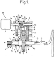
- a rotary assistance mechanism M suitable for being coupled to a rotary receiving member 1, such as a rack and pinion steering gear C for a motor vehicle.
- the receiving member 1 is capable of rotating alternately in both directions in response to the rotation of a coaxial operating shaft 2.
- the connection in rotation between the receiving member 1 and the shaft 2 is ensured by any conventional coupling means 2a allowing axial sliding.
- the receiving member 1 is slidably mounted in bearings P1, P2 and has a toothing 1a, inclined relative to the direction of its axis, so that, during the transmission of a torque, the reaction of the toothing 1a against the cooperating teeth of the rack C has an axial component causing the sliding of the member 1, against elastic return means R.
- the mechanism M comprises a motor 3, preferably electric, capable of turning in a single direction, and means 4 for reducing the speed of the motor, so as to allow the rotary member 1 to be driven at a reduced speed.
- the speed reduction means 4 comprise a gear train whose wheel 5 which rotates the slowest is integral with the rotary member 1; the fastest pinion 6 is mounted idle directly on the output shaft 3a of the motor 3.
- This pinion 6 meshes with a toothed wheel 7 carried by an intermediate shaft 8 of the reducer.
- This toothed wheel 7 is integral with a coaxial pinion 9, of smaller diameter than it, which meshes with the wheel 5.
- the pinion 6 can be linked in rotation to the shaft 3a by means of a first clutch E1.
- Means 10 reversing the direction of rotation are further provided and comprise a gear return including a toothed wheel 11 meshes with a toothed wheel 12 of the same diameter, idle mounted on the shaft 3a; the toothed wheel 11 is integral with a pinion 13 of the same diameter as the pinion 6, and which meshes with the same toothed wheel 7.
- the toothed wheel 11 and the pinion 13 are carried by a return shaft 14, parallel to the shafts 3a and 8.
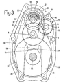
- the shaft 14 is offset transversely, as visible in FIG. 3, to ensure the meshes indicated.
- the toothed wheel 12 of the gear return can be linked in rotation to the shaft 3a by a second clutch E2.
- the receiving member 1 rotates in a first direction when the rotational movement is transmitted, from the shaft 3a, by the clutch E1, the pinion 6, the wheel 7, the pinion 9 and the wheel 5.
- the receiving member 1 rotates in the opposite direction, with the same absolute speed, when the rotational movement is transmitted, from the shaft 3a, by the clutch E2 and the reversing means 10 to the wheel 7.
- the clutches E1, E2 respectively comprise a plate 6a, integral with the pinion 6, and a plate 12a, integral with the wheel 12, capable of being alternately driven in rotation by friction rings 6b, 12b, integral in rotation d 'a player 15 mounted to slide freely on the shaft 3a of the engine; this player 15 is linked in rotation to the shaft 3a by a set of grooves and complementary ribs, parallel to the axis of the shaft 3a.
- the clutch control means E1, E2 comprise a sliding part 16, coaxial with the receiving member 1.
- the part 16 is mounted to rotate freely on the member 1 but is linked in translation to this member.
- the sliding, in the axial direction, of the part 16 and of the member 1 takes place against elastic return means formed by two helical return springs 17, 18.
- the clutch control means E1, E2 further comprise connecting means L between the sliding part 16 and the clutches.
- connecting means L are formed by a movable plate 19, cooperating with the sliding part 16.
- the plate 19 is integral with the part 16. A connection in translation of the plate 19 and the player 15 is ensured by engagement with little or no play, of the corresponding end 19a of the plate in a recess, such as a groove 15a, of the sliding device 15.
- the part 16 can form an integral part of the plate 19, or be fixed to the latter, in particular by screwing or crimping.
- the plate 19 transmits any translation of the part 16 to the player 15.
- the spring 17 is disposed between the bearing P1 and the part 16, with the interposition of the ring 16a.
- the other spring 18 is disposed between the bearing P2 and the wheel 5.
- the operation of the assistance mechanism of FIG. 1 is as follows.
- the part 16 and the plate 19 move in translation with the receiving member 1. This movement is transmitted to the player 15.
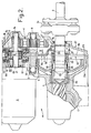
- Figures 2 and 3 illustrate an alternative embodiment in which elements similar to those already described with reference to Figure 1, or playing similar roles, are designated by the same references, possibly supplemented by the letter c, without their description being repeated in detail.
- a free wheel 21 is disposed between the sliding gear 15 and the shaft 3a.
- the arrangement of this freewheel 21 is such that it ensures the rotational drive of the player 15 and therefore of the receiving member 1 by the motor 3 and the shaft 3a in the direction in which this motor 3 can rotate.
- the freewheel 21 prevents the drive 3 in reverse from the motor 15 (and therefore by the drive shaft 2) when the motor 3 is not running.
- the receiving member 1, in the embodiment of FIG. 2, is immobilized axially while remaining free to rotate.
- a cylindrical body 22, coaxial with the member 1 is slidably mounted in the axial direction, in a blind bore of the member 1; this body 22 can slide on either side of a rest position against elastic return means formed by a single double-acting spring 23, depending on whether the operating torque exerted on the shaft 2 is directed one way or the other.
- the axial thrust of the body 22, in response to the exercise of a torque on the shaft 2, is obtained by reaction, against the inclined edges of slots 24 formed in the rotary member 1, of rollers 25 carried by an axis 26 engaged in a diametrical bore of the cylindrical body 22; the axis 26 is integral in rotation and in translation with the body 22.
- the sliding part 16c is formed by the outer ring of a ball bearing 27 whose inner ring is fixed in translation and in rotation on the body 22. The part 16c is therefore free to rotate relative to the body 22 but linked in translation to this body.
- connection plate 19c comprises a curved intermediate portion 28, a border of which is engaged in a recess 29 of the part 16c, as visible in FIGS. 2 and 3.
- the other end portion of the plate 19c also forms a fork 34 (fig.3) with two branches 35, 36, the ends of which are immobilized between two elements 37a, 37b (fig.2) of the casing 37 containing the means reduction and shafts of the mechanism.
- the branches 35, 36 are relatively thin and long so as to have sufficient flexibility to allow the middle portion 28 to accompany any sliding of the part 16c by tilting slightly, so that the fork 30, located at the other end, transmits to the player 15 an amplified translational movement relative to that of the part 16c.
- FIGS. 2 and 3 The operation of the assistance mechanism in FIGS. 2 and 3 is similar to that in FIG. 1.
- the exercise of a torque on the operating shaft 2 causes the body 22 to slide axially against the elastic return means 23.
- the part 16c moves with the body 22.
- This translational movement is amplified by the connection plate 19c and transmitted to the player 15.
- the clutch E1 or E2, associated with the direction of movement, is put into action if this movement is sufficient.
- the assistance of the rotation of the member 1 is then ensured by the motor.
- the clutches E1, E2 of FIGS. 1 and 2, and the freewheel 21 of FIG. 2 can be reduced in size. In fact, they have only a small torque to transmit since they are arranged on a shaft rotating faster than the rotary member 1 and therefore subjected to a lower torque.
- the clutches E1, E2 and the freewheel 21 are provided directly on the shaft 3a, that is to say at the input of the reduction means, therefore on the fastest shaft .
- the ratio of the torque on the rotary member 1 to the torque supported by the clutches E1, E2 and the freewheel 21 is therefore equal to the reduction ratio of the reduction means (input speed / output speed).
- the movable plate 19, 19 c which exerts this thrust is therefore only subjected to minor efforts; it can be of light construction and only introduces negligible resistance to the rotation of the member 1 by axial thrust of the part 16 against the support rings 16a, 16b or by axial thrust of the part 16c formed by the outer ring of a bearing.
- connections of the movable plate 19, 19c with the player 15, the part 16 or 16c and the housing 37 could form joints.
- the branches 35, 36 of the fork 34 (fig. 3) could be rigid, the plate 19c then constituting an articulated lever.
Landscapes
- Engineering & Computer Science (AREA)
- Chemical & Material Sciences (AREA)
- Combustion & Propulsion (AREA)
- Transportation (AREA)
- Mechanical Engineering (AREA)
- Transmission Devices (AREA)
- Power Steering Mechanism (AREA)
Claims (9)
Applications Claiming Priority (2)
| Application Number | Priority Date | Filing Date | Title |
|---|---|---|---|
| FR8022967 | 1980-10-27 | ||
| FR8022967A FR2492759A1 (fr) | 1980-10-27 | 1980-10-27 | Perfectionnements apportes aux mecanismes d'assistance rotative, notamment pour direction de vehicule |
Publications (2)
| Publication Number | Publication Date |
|---|---|
| EP0051515A1 EP0051515A1 (de) | 1982-05-12 |
| EP0051515B1 true EP0051515B1 (de) | 1984-06-13 |
Family
ID=9247360
Family Applications (1)
| Application Number | Title | Priority Date | Filing Date |
|---|---|---|---|
| EP81401619A Expired EP0051515B1 (de) | 1980-10-27 | 1981-10-15 | Rotationsservogetriebe, insbesondere für Fahrzeuglenkungen |
Country Status (5)
| Country | Link |
|---|---|
| US (1) | US4416345A (de) |
| EP (1) | EP0051515B1 (de) |
| JP (1) | JPS5799467A (de) |
| DE (1) | DE3164214D1 (de) |
| FR (1) | FR2492759A1 (de) |
Families Citing this family (31)
| Publication number | Priority date | Publication date | Assignee | Title |
|---|---|---|---|---|
| US4576056A (en) * | 1982-07-16 | 1986-03-18 | Automobiles Citroen | Rotary assistance mechanism, particularly for vehicle steering |
| JPS5970257A (ja) * | 1982-10-14 | 1984-04-20 | Aisin Seiki Co Ltd | 電動パワ−ステアリング装置 |
| JPS59100059A (ja) * | 1982-11-30 | 1984-06-09 | Aisin Seiki Co Ltd | 電動パワ−ステアリング装置 |
| JPS59130781A (ja) * | 1983-01-17 | 1984-07-27 | Aisin Seiki Co Ltd | 電動パワ−ステアリング装置 |
| JPS6053463A (ja) * | 1983-09-01 | 1985-03-27 | Aisin Seiki Co Ltd | 操舵力伝達装置 |
| FR2556681B1 (fr) * | 1983-12-16 | 1988-04-08 | Citroen Sa | Direction de vehicule automobile a commande assistee par un moteur electrique |
| JPS6133367A (ja) * | 1984-07-25 | 1986-02-17 | Aisin Seiki Co Ltd | 電動パワ−ステアリングの動力伝達装置 |
| JPH0412863Y2 (de) * | 1984-12-05 | 1992-03-26 | ||
| JPH0615331B2 (ja) * | 1985-06-12 | 1994-03-02 | 株式会社日立製作所 | 電動式パワ−ステアリング装置 |
| DE3714833A1 (de) * | 1986-05-14 | 1987-11-19 | Zahnradfabrik Friedrichshafen | Hilfskraftlenkung fuer kraftfahrzeuge |
| FR2639598B1 (fr) * | 1988-11-29 | 1993-05-14 | Renault | Dispositif de braquage des roues arriere d'un vehicule a quatre roues directrices |
| JPH02189270A (ja) * | 1989-01-19 | 1990-07-25 | Atsugi Unisia Corp | 電動パワーステアリング装置 |
| DE3933771A1 (de) * | 1989-10-10 | 1991-04-18 | Bosch Gmbh Robert | Elektromotorische servolenkung |
| DE4025697A1 (de) * | 1990-08-14 | 1992-02-20 | Danfoss As | Lenkeinrichtung |
| FR2670456B1 (fr) * | 1990-12-14 | 1995-07-07 | Cartier Systemes G | Mecanisme d'assistance temporaire pour colonne de direction de vehicules a roues directrices. |
| DE4321670C1 (de) * | 1993-06-30 | 1994-12-01 | Jungheinrich Ag | Elektromotorische Servolenkung |
| KR100204643B1 (ko) * | 1993-09-20 | 1999-06-15 | 홍순영 | 전자식 동력조향장치 |
| DE4438930C1 (de) * | 1994-10-31 | 1995-10-26 | Daimler Benz Ag | Zahnstangenlenkung bzw. -steuerung mit Servomotor |
| JP3411726B2 (ja) * | 1995-05-01 | 2003-06-03 | 光洋精工株式会社 | 電動パワーステアリング装置 |
| US6026925A (en) * | 1995-12-19 | 2000-02-22 | Denso Corporation | Electrically driven power assisting device |
| JPH09226607A (ja) * | 1995-12-19 | 1997-09-02 | Denso Corp | パワーステアリング装置用電動機およびこの電動機を用いたパワーステアリング装置 |
| DE19743961A1 (de) * | 1997-10-04 | 1999-04-15 | Mercedes Benz Lenkungen Gmbh | Lenkhelfeinrichtung für ein Kraftfahrzeug |
| DE19827869A1 (de) * | 1998-06-23 | 1999-12-30 | Bosch Gmbh Robert | Lenkvorrichtung für ein Fahrzeug |
| CN1144712C (zh) * | 1999-03-30 | 2004-04-07 | 泰森克鲁普普里斯塔股份公司 | 带有紧凑的正齿轮变速器装置的电力转向助力器 |
| JP2001301630A (ja) * | 2000-04-25 | 2001-10-31 | Showa Corp | 電動パワーステアリング装置 |
| DE10342681B3 (de) * | 2003-09-16 | 2005-04-21 | Thyssenkrupp Automotive Ag | Fahrzeuglenkung mit einer Übersetzungsverhältnisänderungseinrichtung |
| US20060042861A1 (en) * | 2004-08-24 | 2006-03-02 | Ovshinsky Stanford R | Steering assist mechanism |
| DE102004059461A1 (de) * | 2004-12-10 | 2006-06-14 | Zf Lenksysteme Gmbh | Lenkung |
| US11022200B2 (en) | 2014-06-06 | 2021-06-01 | Delbert Tesar | Simplified parallel eccentric rotary actuator |
| US11166864B2 (en) | 2016-12-06 | 2021-11-09 | Delbert Tesar | Actuators for patient mobility devices, patient healthcare devices and human prosthetics |
| US10793183B2 (en) * | 2017-12-22 | 2020-10-06 | Trw Automotive U.S. Llc | Torque overlay steering apparatus |
Family Cites Families (10)
| Publication number | Priority date | Publication date | Assignee | Title |
|---|---|---|---|---|
| US2833154A (en) * | 1952-09-27 | 1958-05-06 | William B Barnes | Torque amplifier unit |
| US2736208A (en) * | 1953-03-17 | 1956-02-28 | Follow-up mechanism | |
| FR1540365A (fr) * | 1967-04-13 | 1968-09-27 | Piat Ets | Perfectionnements aux commandes sensitives |
| GB1205223A (en) * | 1967-11-29 | 1970-09-16 | Lansing Bagnall Ltd | Improvements in or relating to power-assisted steering mechanisms. |
| BE756029R (fr) * | 1969-09-12 | 1971-03-11 | Ciba Geigy | Procede de preparation de substances solides hautement dispersees, constituees par des produits de polycondensation reticules a base d'uree etde |
| JPS4893037A (de) * | 1972-03-14 | 1973-12-01 | ||
| JPS492730A (de) * | 1972-04-26 | 1974-01-11 | ||
| GB1590629A (en) * | 1976-09-23 | 1981-06-03 | Cam Gears Ltd | Powerassisted gear system |
| DE2746919A1 (de) * | 1977-10-19 | 1979-04-26 | Zahnradfabrik Friedrichshafen | Servolenkvorrichtung fuer kraftfahrzeuge |
| DE2806307A1 (de) * | 1978-02-15 | 1979-08-23 | Bosch Gmbh Robert | Kraftuebertragungseinrichtung |
-
1980
- 1980-10-27 FR FR8022967A patent/FR2492759A1/fr active Granted
-
1981
- 1981-10-15 EP EP81401619A patent/EP0051515B1/de not_active Expired
- 1981-10-15 DE DE8181401619T patent/DE3164214D1/de not_active Expired
- 1981-10-23 JP JP16993281A patent/JPS5799467A/ja active Pending
- 1981-10-26 US US06/315,048 patent/US4416345A/en not_active Expired - Fee Related
Also Published As
| Publication number | Publication date |
|---|---|
| FR2492759A1 (fr) | 1982-04-30 |
| DE3164214D1 (en) | 1984-07-19 |
| JPS5799467A (en) | 1982-06-21 |
| US4416345A (en) | 1983-11-22 |
| FR2492759B1 (de) | 1983-01-21 |
| EP0051515A1 (de) | 1982-05-12 |
Similar Documents
| Publication | Publication Date | Title |
|---|---|---|
| EP0051515B1 (de) | Rotationsservogetriebe, insbesondere für Fahrzeuglenkungen | |
| EP0148664B1 (de) | Durch elektrischen Motor unterstützte Kraftfahrzeuglenkung | |
| FR2620185A1 (fr) | Embrayage pour dispositif de direction assistee electrique | |
| EP4247657A1 (de) | Elektrische antriebsvorrichtung für eine fahrzeugachse | |
| FR2706004A1 (fr) | Frein à disque utilisable sur les véhicules industriels. | |
| EP0081025B1 (de) | Rotationsservomechanismus, insbesondere für eine Fahrzeuglenkung | |
| EP0011579A1 (de) | Vorrichtung zur Steuerung der Drehung eines drehenden Empfangsgliedes | |
| EP3959449A1 (de) | Getriebegehäuse und radfahrzeug mit einem solchen getriebegehäuse | |
| FR3056160A1 (fr) | Transmission pour vehicule automobile a propulsion electrique | |
| FR2728528A1 (fr) | Direction a cremaillere | |
| EP0321335B1 (de) | Differentialsystem mit veränderlichem gesteuertem Schlupf | |
| FR2837773A1 (fr) | Appareil de direction du vehicule | |
| FR2838176A1 (fr) | Commande interne de boite de vitesses | |
| FR2917797A1 (fr) | Transmission entre un organe moteur et des roues et engin comportant une telle transmission | |
| EP0819864B1 (de) | Kompakte Synchronisiereinrichtung für ein Zahnradwechselgetriebe, insbesondere für ein Kraftfahrzeug | |
| EP0390688B1 (de) | Servosteuerungseinrichtung für durch ein Torsionselement verbundene Ober- und Unterwelle, insbesondere für die Lenkwelle eines Fahrzeuges | |
| EP1538051B1 (de) | Notbetätigungseinrichtung für eine elektromechanische Betriebsbremse | |
| FR2883061A1 (fr) | Boite de vitesses a double arbre primaire comprenant un systeme de butees axiales et vehicule automobile comprenant une telle boite de vitesses | |
| EP1490945A1 (de) | Bremsscheiben- und drehmomentnockenantrieb | |
| FR2830301A1 (fr) | Dispositif d'entrainement en rotation alternatif de deux arbres menes montes concentriques a partir d'un seul arbre d'entrainement | |
| EP1631750B1 (de) | Mit einer schrauben-/mutteranordnung versehener betätigungshebel | |
| FR2745348A3 (fr) | Dispositif d'embrayage ameliore, destine a l'embrayage et au debrayage de deux arbres | |
| FR2742205A1 (fr) | Dispositif de rattrapage de jeu d'engrenage | |
| FR2568387A1 (fr) | Dispositif de commande a cable pour crabotage, notamment pour groupes de transmission de vehicules automobiles et groupe de transmission de vehicule automobile comportant un tel dispositif de commande | |
| FR2638500A1 (fr) | Differentiel autobloquant a train epicycloidal |
Legal Events
| Date | Code | Title | Description |
|---|---|---|---|
| PUAI | Public reference made under article 153(3) epc to a published international application that has entered the european phase |
Free format text: ORIGINAL CODE: 0009012 |
|
| AK | Designated contracting states |
Designated state(s): DE GB IT SE |
|
| 17P | Request for examination filed |
Effective date: 19820521 |
|
| ITF | It: translation for a ep patent filed |
Owner name: UFFICIO TECNICO ING. A. MANNUCCI |
|
| GRAA | (expected) grant |
Free format text: ORIGINAL CODE: 0009210 |
|
| AK | Designated contracting states |
Designated state(s): DE GB IT SE |
|
| REF | Corresponds to: |
Ref document number: 3164214 Country of ref document: DE Date of ref document: 19840719 |
|
| PLBE | No opposition filed within time limit |
Free format text: ORIGINAL CODE: 0009261 |
|
| STAA | Information on the status of an ep patent application or granted ep patent |
Free format text: STATUS: NO OPPOSITION FILED WITHIN TIME LIMIT |
|
| 26N | No opposition filed | ||
| ITPR | It: changes in ownership of a european patent |
Owner name: OFFERTA DI LICENZA AL PUBBLICO |
|
| REG | Reference to a national code |
Ref country code: GB Ref legal event code: 746 |
|
| PGFP | Annual fee paid to national office [announced via postgrant information from national office to epo] |
Ref country code: GB Payment date: 19921009 Year of fee payment: 12 |
|
| PGFP | Annual fee paid to national office [announced via postgrant information from national office to epo] |
Ref country code: SE Payment date: 19921028 Year of fee payment: 12 |
|
| ITTA | It: last paid annual fee | ||
| PGFP | Annual fee paid to national office [announced via postgrant information from national office to epo] |
Ref country code: DE Payment date: 19921104 Year of fee payment: 12 |
|
| PG25 | Lapsed in a contracting state [announced via postgrant information from national office to epo] |
Ref country code: GB Effective date: 19931015 |
|
| PG25 | Lapsed in a contracting state [announced via postgrant information from national office to epo] |
Ref country code: SE Effective date: 19931016 |
|
| GBPC | Gb: european patent ceased through non-payment of renewal fee |
Effective date: 19931015 |
|
| PG25 | Lapsed in a contracting state [announced via postgrant information from national office to epo] |
Ref country code: DE Effective date: 19940701 |
|
| EUG | Se: european patent has lapsed |
Ref document number: 81401619.2 Effective date: 19940510 |