EP0051199A1 - Vorrichtung zum Kartonieren eines in etwa halbkugelförmigen Zellen angeordneten Produktes - Google Patents
Vorrichtung zum Kartonieren eines in etwa halbkugelförmigen Zellen angeordneten Produktes Download PDFInfo
- Publication number
- EP0051199A1 EP0051199A1 EP19810108492 EP81108492A EP0051199A1 EP 0051199 A1 EP0051199 A1 EP 0051199A1 EP 19810108492 EP19810108492 EP 19810108492 EP 81108492 A EP81108492 A EP 81108492A EP 0051199 A1 EP0051199 A1 EP 0051199A1
- Authority
- EP
- European Patent Office
- Prior art keywords
- plates
- carriage
- plate
- cutting
- receiving
- Prior art date
- Legal status (The legal status is an assumption and is not a legal conclusion. Google has not performed a legal analysis and makes no representation as to the accuracy of the status listed.)
- Granted
Links
Images


Classifications
-
- B—PERFORMING OPERATIONS; TRANSPORTING
- B65—CONVEYING; PACKING; STORING; HANDLING THIN OR FILAMENTARY MATERIAL
- B65B—MACHINES, APPARATUS OR DEVICES FOR, OR METHODS OF, PACKAGING ARTICLES OR MATERIALS; UNPACKING
- B65B35/00—Supplying, feeding, arranging or orientating articles to be packaged
- B65B35/30—Arranging and feeding articles in groups
- B65B35/50—Stacking one article, or group of articles, upon another before packaging
-
- B—PERFORMING OPERATIONS; TRANSPORTING
- B65—CONVEYING; PACKING; STORING; HANDLING THIN OR FILAMENTARY MATERIAL
- B65B—MACHINES, APPARATUS OR DEVICES FOR, OR METHODS OF, PACKAGING ARTICLES OR MATERIALS; UNPACKING
- B65B5/00—Packaging individual articles in containers or receptacles, e.g. bags, sacks, boxes, cartons, cans, jars
- B65B5/06—Packaging groups of articles, the groups being treated as single articles
-
- B—PERFORMING OPERATIONS; TRANSPORTING
- B65—CONVEYING; PACKING; STORING; HANDLING THIN OR FILAMENTARY MATERIAL
- B65B—MACHINES, APPARATUS OR DEVICES FOR, OR METHODS OF, PACKAGING ARTICLES OR MATERIALS; UNPACKING
- B65B5/00—Packaging individual articles in containers or receptacles, e.g. bags, sacks, boxes, cartons, cans, jars
- B65B5/10—Filling containers or receptacles progressively or in stages by introducing successive articles, or layers of articles
- B65B5/108—Article support means temporarily arranged in the container
-
- B—PERFORMING OPERATIONS; TRANSPORTING
- B65—CONVEYING; PACKING; STORING; HANDLING THIN OR FILAMENTARY MATERIAL
- B65B—MACHINES, APPARATUS OR DEVICES FOR, OR METHODS OF, PACKAGING ARTICLES OR MATERIALS; UNPACKING
- B65B61/00—Auxiliary devices, not otherwise provided for, for operating on sheets, blanks, webs, binding material, containers or packages
- B65B61/04—Auxiliary devices, not otherwise provided for, for operating on sheets, blanks, webs, binding material, containers or packages for severing webs, or for separating joined packages
- B65B61/06—Auxiliary devices, not otherwise provided for, for operating on sheets, blanks, webs, binding material, containers or packages for severing webs, or for separating joined packages by cutting
- B65B61/065—Auxiliary devices, not otherwise provided for, for operating on sheets, blanks, webs, binding material, containers or packages for severing webs, or for separating joined packages by cutting by punching out
Definitions
- the present invention relates to an apparatus : canning from precut plates forming the support of a product, for example ice cream at low temperature, filling pseudo-hemispherical cells arranged on said plates, and staggered arrangement of the latter of said plates inside said box.
- the present invention overcomes this insufficiency by providing a boxing device according to the three dimensions of objects with a round body and more particularly pseudo-hemispherical objects having a flat face and housed in cells formed on precut plates.
- objects may be, for example, already solidified ice cream scoops.
- the apparatus according to the invention is essentially characterized by the fact that it comprises: a platform forming a support for a carriage, on which are mounted two plates for receiving pre-cut wafers and movable in horizontal translation alternately between two extreme positions one corresponding to a loading position, and the other to a position for cutting said plates into elementary portions and ejecting said portions, said plates themselves being movable in horizontal translation relative to the carriage in a direction inclined to 45 ° relative to the direction of translation of said carriage between two extreme positions separated by a distance equal to the half-diagonal of the square formed by joining the centers of four contiguous cells; a horizontal plate for receiving the successive layers of elementary portions of wafers thus cut, movable in vertical translation alternately between two extreme positions, the upward translation being carried out continuously, while the downward translation, is carried out, in successive steps, at the inside a package along the internal walls of which it moves; and a device for controlling said receiving plate cooperating with a set of control and automatic coordination members for the various movements of the entire device.
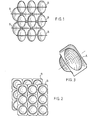
- the product to be canned by means of the apparatus according to the invention is for example constituted by "balls" of ice cream previously conditioned in the form of elementary portions , that is to say solids conforming to the shape of pseudo-hemispherical cells, regularly arranged in length and in width. on “plates” (B) made of sheet plastic. Said cells and, consequently, the "balls” of ice cream have a shape such that they have on one side a circular transverse planar face and on the opposite side the shape of a pseudo-hemispherical cap and a lateral connection face. substantially frustoconical, as shown in particular in Figures 1 and 3.
- the centers of cells A represent the vertices of a square mesh network.
- the length of the side of the base square is chosen so that, taking into account the height of a cell, it can be placed, inverted, between four cells of the adjacent plate so that its lateral face is tangent to each of the lateral faces of said four cells, as shown in FIGS. 1 and 2.
- the number of pairs of plates that can be stacked in the same box can be any number, but the pairs of plates of even rank from the bottom of the box are all offset in the manner indicated above with respect to the pairs of plates. of odd rank.
- each plate can advantageously be of square shape and include nine cells regularly spaced apart in two dimensions, the centers of the circles forming their flat faces thus being arranged at the vertices of the squares forming a network with regular square meshes of nine squares.
- each receiver box can contain, for example, five pairs of two plates each joined by their plane faces, that is to say in total ten plates of nine balls each, the pairs of plates of even rank being offset from that of odd rank, along the same diagonal of the square and of a length equal to the half-diagonal of an elementary square.
- the apparatus essentially comprises mounted on chassis 1: a platform 2 on which can move in horizontal rectilinear translation and in both directions, a carriage 3 forming a support for two plates 4 and 5 platelet receptors; an assembly 6 for cutting said wafers, and for evacuating the latter in a box, below and plumb with which the two said trays loaded with a wafer are placed alternately; a plate 7 forming a support for the boxes, which cooperates with a mechanism which causes it to descend step by step as and when the plates are stacked in the receiving box; and, a set of means for closing and evacuating the filled boxes.
- a carriage 3 On the horizontal platform 2 can move by means of guide members of any suitable known type, a carriage 3 on which are arranged at each of its two ends, the two plates 4 and 5.
- Each of these two trays 4 and 5 is shaped to receive such wafers, the cells of which have been previously filled with ice cream. To this end, it includes as many cells for receiving cells as there are cells in a wafer of ice cream "balls", that is to say nine in this case and arranged in the same way as said cells as shown in Figure 6.
- the two plates which are integral with the carriage move at the same time as it in horizontal translation, straight bars or rails 2a and 2b forming a guide for rollers 3a and 3b integral with the carriage constituting, for example, the bodies of guiding this movement.
- the device is assumed to be viewed from the front, that is to say as shown in FIG. 4, so that the plate 4 is the plate on the left and the plate 5 is the plate on the right.
- This horizontal translation movement takes place between two extreme positions, sometimes from the right to the left, sometimes from the left to the right, and in such a way that, when the left plate 4 is in the extreme position, it is in the receiving position of a plate of "balls", while the right plate 5 previously loaded with a plate is directly above the assembly 6 for cutting and evacuating the plates. Similarly, when the right tray is in the extreme position, the left tray previously loaded with a wafer, is plumb with the cutting assembly.
- each of the plates 4 and 5 is mounted in a known manner on two slides 5a which are integral with it and cooperate with, for example, guide rods 5b fixed relative to the carriage, as shown in FIG. 6.
- both of the carriage and of the plates are obtained by means, for example, of jacks (not shown), the ends of the rods of which are made respectively integral both with the carriage and with each of the two plates, said movements being coordinated with each other by means of any suitable known device, and as described below.
- the plates situated on the same side of the carriage are loaded, for example manually, so that the concavity of the cells of the plates placed on a plate are always oriented in the same direction, and the concavity of the cells of the plates, placed in place on the plate opposite to the previous one are oriented in the opposite direction.
- the cells of the wafers placed on the right tray always have their concavity turned upwards, said cells thus being housed on the tray so that each of them is placed in a box of the corresponding tray, while that the cells of the wafers placed on the left plate are arranged so that their concavity is turned downwards, said cells then having their flat face arranged opposite the boxes of the corresponding plate.
- the plates are provided with lateral claws for retaining the plates which are placed there, and the positioning of which is controlled automatically upon setting in motion, in order to avoid any unwanted displacement of the latter.
- the plates pre-cut and whose cells have been filled, with ice cream, in the solid state, are placed on the plates 4 and 5 as just indicated, said plates occupying the same extreme position on the carriage.
- the carriage in a first phase, is moved so that the right plate comes to be placed directly above the assembly 6 for cutting the wafers and that, as explained below, it can be discharged through a member of this set m m e - 6 in a receiving box.
- the carriage is moved in the opposite direction to the previous one until the left plate comes to place itself in line with the assembly 6, then after cutting of the wafer which it supports, evacuated by means of the ejection members associated with the cutting device in the receiving box, directly above the wafer which has been previously arranged there, the two wafers then being exactly symmetrical l ' one of the other, compared to the common plane by which they face each other.
- the device for cutting and ejecting the elementary portions of cut wafers is mounted on the carriage so that it is kept stationary during the overall movement of the carriage and that it can, on the contrary, move obliquely relative to the direction of the latter at the same time as the two plates, so that it is always plumb with one or the other plate, in the cutting phase.
- the plate 7, which, as indicated below in more detail, is integral with a column 8 formed of two support rods, is movable between two extreme positions, one upper, the other lower.
- the boxes 9 for receiving the wafers which, most often are made of a material capable of supporting folding along. rectilinear parts, such as for example cardboard, have a square cross section so that two successive plates placed in staggered rows with respect to each other each bear on two of their adjacent sides on the internal wall of the corresponding box.
- the plate 7 is located at level 10 of an evacuation device (not shown) of the filled box.
- edges 9a, 9b, 9c, and 9d of the upper part of the box 9 are folded down along the corresponding external lateral faces of the latter and held in this position as follows: the edges 9a and 9b are kept folded down respectively by the edge 9b of the empty box preceding the box to be filled and by the edge 9a of the box which has just been filled, while the edges 9c and 9a are kept folded down by and between flanges 11a and 11b integral with the machine frame.
- edges 9e, 9f, 9g and 9h of the lower part of the box are folded outwards at 90 °, have their internal faces applied on the upper face of level 10 and are held by means of the angles 12a and 12b secured to the frame of the machine, while the edges 9g, 9h are folded outwardly and maintained, like the corresponding edges of the upper part of the box, by the lower edges of the adjacent boxes.
- the plate 7 When the box ready to be filled has been thus placed, the plate 7, is raised from level 10 in the manner indicated below, until it is flush with the upper contour of the box as shown in Figures 4 and 5; the box is then ready to receive the layers of platelets for their installation, after cutting into elementary portions, with the staggered arrangement as described above.
- the right tray On which the ball plates are placed so that the concavity of their cells faces upwards, is brought loaded directly above the cutting assembly 6 and ejection of said plates.
- This assembly 6 essentially comprises, mounted on the upper part of the chassis 1, at least one, but preferably two cylinders 13a and 13b, fluid under pressure, for example hydraulic, with vertical longitudinal axes, and whose rods, placed on the bottom side, have their ends rigidly secured to a cutting block 14.
- the latter comprises two groups of pairs of blades arranged parallel to each other and regularly spaced; the two parallel blades of a pair, the cutting edges of which are at the same level, have a length equal to that of the side of the square forming the outline of a compartment of a platelet receiving tray and cover the parts of the platelets not affected by the precut between two adjacent cells.
- the planes containing the blades of the first group are perpendicular to the direction of movement of the carriage 3, while the planes containing the blades of the second group are parallel to the direction of movement of this same carriage. Furthermore, this cutting block is provided on each of its four sides with two guide rods.
- each of the pairs of the cutting block is then placed directly above a partition separation of the cells, a blade of each pair then being plumb with a partition dividing two adjacent boxes of the corresponding tray.
- each of the upper parts of the partitions dividing the cells of the platelet receiving tray comprises, opposite the corresponding blade, a cavity of complementary shape of this same blade over a certain depth, into which the coresponding blade can sink, after having crossed the wafer and having made the cutting notch there.
- the corresponding simultaneous vertical movements of the different blades are caused by the simultaneous extensions of the rods of the cutting cylinders 13a and 13b.
- the wafer is then cut into nine parts or elements of general square contour each comprising a cell, these elements no longer resting then by the edge of their contour on the walls of the corresponding box of the receiving tray 4 or 5.
- the set 6 for cutting the plates further comprises a tool for ejecting the portions of square contour plates resting on the plate 7 where they have been cut out of this plate.
- This tool is constituted by a set of ejectors 16 formed by pushers integral with a common support 17 arranged on this support respectively opposite the cells.
- the support for the ejectors is made integral with the end of the rod of an actuator 18 integral with a frame of longitudinal axis parallel to the longitudinal axes of the actuating cylinders for cutting tools for the inserts on the plates, said actuator being placed at a height such that the distance separating the point of its course corresponding to the contact of the free end of an ejector with the corresponding ice cream cell and the point of its race corresponding to that where said cell was ejected of the tray and pushed back into the box is equal to the height of a cell, the level at which the vertices of the nine cells alternately or their flat face being that of the orifice of the ball receiving box.
- This ejection operation and introduction into the receiving box 9 of the nine cells simultaneously is made possible by the fact that the support material for the ice cream balls provided with such cells is a flexible sheet material and elastic at the same time.
- the edges of the nine cavities forming the nine cells filled with ice cream which, before the ejection rested on the edge of the square contour cavities of the corresponding platelet receiving tray, fold back under the effect of the thrust of the ejection corespondant thanks to their flexibility, which allows them to cross folded said cavities by resting on the inner faces of the latter, and to resume thanks to their elasticity their initial planar shape once this crossing made.
- the plate of the ice cream scoop is pushed down the height of a cell in the manner indicated below.
- the square tray 7 receiving boxes 9 is supported in its central region by an olonnne 8 formed by a set of two vertical rods 19 of the same length.
- These rods 19 are interconnected by bars 20 forming notches regularly staggered together and the number of which is at least equal to the number of layers of balls stacked in staggered rows in a box.
- these rods are guided in vertical axial translation by means of at least two groups of two rollers 21 each carried by yokes 22 made integral with the chassis of the device by any suitable known means.
- each group of two guide rollers the rollers which can rotate freely around their axes are placed so that they are opposite to each other, their grooves or raceway bearing on the outer lateral faces of the rods 19, that is to say those opposite the inner side faces connected together by the bars 20 and can rotate without sliding when the rods move.
- the two rods 19 are secured to each other at their ends by a spacer plate 23.
- the two rods 19 are also in permanent contact with a brake, the two jaws 24 and 25 of which bear by their internal faces respectively on the two rods 20.
- These jaws are joined together by two rods 26 and 27 secured to the chassis.
- the device and arranged horizontally and parallel to the vertical plane containing the vertical axes of the rods 20. At least one of these two jaws can slide along the support rods, the other being kept pressed on the corresponding rod 20, the jaw sliding then being pressed against the corresponding rod by any suitable known means by means of a compressible elastic member, for example a compressible spring bearing directly or indirectly on the one hand on the jaw and, on the other hand, on the device chassis.
- each of the two jaws can be mounted so as to bear on the corresponding rod by means of a compressible spring.
- the mechanical characteristics of the compression springs are chosen such that. the friction forces exerted in contact with the jaws and the rods are sufficient to prevent the descent against these forces under the effect of its own weight of the assembly formed by the plate .7, the rods 19 and their connecting elements 20 and 23 as well as the weight of the total maximum load of the platform 7, but that, on the other hand, this descent can be obtained by means of a thrust of appropriate value added to the weight of this assembly, as for example, the thrust exerted by the actuator for ejecting the ice cream scoops out of their support plate, this movement of descent of the plate 7 and of all the elements which are linked to it ceasing as soon as this thrust ceases.
- a pawl 28 articulated around an axis 29 parallel to the rods 26 and 27 forming their supports.
- This pawl comprises on one side of the axis 28, one end cooperating with the various bars 20 as the descent of the packaging carrier plate 7 and on the other side of this same axis a connected end 28b, by means of an elastic extensible member, for example, a spring 30, to a ratchet clevis 31, also articulated around the axis 29 of said pawl.
- This yoke cooperates with the rod 32 of a jack 33 secured to the chassis of the apparatus for its maintenance in a fixed position during the downward movement of the plate 7, a housing being provided for this purpose for the end of the rod of said cylinder.
- the ratchet yoke comprises, on its face opposite to the rods 19 tray holder 7 and on the other side of its axis 29 relative to these same rods, a part provided with a fork 34 with two branches, open on the side opposite to said rods 19, the role of which will be explained later.
- the device for lowering the plate 7 as described above further comprises a vertical pendulum 35 articulated around a horizontal axis parallel to the axis of rotation 29 of the pawl, integral with the chassis of the apparatus and disposed at a level lower than that of said axis 29.
- This balance comprises, at its upper end, a ratchet guide formed by a cylindrical rod 35a, which is engaged in the fork 34 of the ratchet yoke, when said balance is. in vertical rest position.
- This balance comprises, in addition, at its lower end a roller 35b whose axis of rotation, parallel to its own axis of oscillation is eccentric with respect to it and disposed on the side of the rods 19, the axis of said roller being secured to the balance rod via a yoke 35c which is made integral with any suitable known means, for example, by welding.
- the balance rod is connected to the chassis of the device by an elastic elastic member 36 which urges it under traction, so that naturally and apart from any other constraint, the part of said pendulum placed above its axis of rotation is attracted to the side of this chassis, that is to say moves away from the rods 19, this displacement remaining however limited by a length stop adjustable 37, while the part situated above this axis, and consequently, the roller 35b, approaches it, the pawl guide then not being, in this position, no longer engaged with the pawl yoke by the fork 34.
- This part of the device finally comprises a jack 38 whose body is secured to the frame by any suitable known means and whose rod 38a, provided at its end with a pusher 38b is extendable downwards and retractable upwards.
- Said pusher cooperates on the one hand, by its plate when the cylinder rod is in the extended position, with the roller 35b to maintain the balance in the vertical position, which has the effect of returning, by means of the ratchet guide 35a, the clevis of the pawl in the working position and thus obtain the locking, by means of the rod 32, of the jack 33, and, on the other hand, also by this same plate, with the spacer plate of the rods 19 to reassemble the said rods and consequently the plate 7, when, after its descending movements in successive steps, it is lowered by a height equal to that of its stroke, which corresponds to the height of a box 9.
- the rod of the jack 38 returns as indicated below, in position extension, position in which, after having attacked the roller 35b of the pendulum 35, the pusher 38b brings it back then maintains it in the vertical position, which has the effect of bringing the ratchet yoke and, consequently, the ratchet in position working position in which the end of the rod 32 of the jack 33 is placed in the housing provided for this purpose in the ratchet yoke to keep it fixed throughout the duration of the new descent of the plate 7.
- the reception box At the end of the descent of the plate 7, that is to say when the reception box is filled, it is pushed out of the plate onto a packaging machine, by an empty box which then takes its place on the tray, a jack whose end of the rod is provided with a pusher being provided for this purpose, and the empty box in turn pushing the full box.
- control of the running and / or stopping of the various pressurized fluid cylinders ensuring the movements m ents of the various organs described above and the coordination of said movements is obtained by means of any suitable control device of known type which can implement various means, for example, electrical, electronic, electromagnetic, mechanical, pneumatic or a combination of these various means.
- the spacer 23 connecting the rods 19 forms the support of a part provided with cams cooperating with a movable member, along which said cams travel as the descent of the plate 7.
- the support of said cams is constituted, for example, by a square-shaped piece 39 having as plane of symmetry the vertical plane containing the longitudinal axes of the two rods 29, fixed by any suitable known means, by its horizontal branch 39a to the spacer 23, while its vertical branch 39b, at the free upper end, is provided with cams constituted, for example, by a series of notches 39c and redents 39d regularly spaced apart over part of the height of said upper end and cooperating with a roller 40 movable both in rotation about its axis and in rotation around an axis of rotation parallel to the previous one, fixed relative to the chassis, the link arm of the yoke of the roller to this axis being constrained by a .organ elastic return, so that the roller finds its natural position in the notches 39c and the spring is constrained when the roller is pushed on a redent 39d between two notches 39c.
- This laision arm is integral with closing (and opening) members of the control circuits of the various members of the apparatus, which therefore
- the control member of the actuator 1 3 controls the starting of its rods 13a and 13b, an operation which results in the complete cutting of the precut plate. in place on the tray 5.
- This operation causes said balls to pass through the tray, a push and a descent of the tray 7 on which the first layer of balls then rests inside the box 9 previously put in place, over a height equal to the height separating the plane of the flat face of a plate from that of the flat face of one of the two plates which are adjacent to it in the stacking of the box.
- the control circuits of the organs of the apparatus are chosen in such a way that in this new position, the actuators for controlling the oblique translation of the assembly of the carriage 2 tray holders and of the assembly 6 for cutting and ejection of the ice cream balls linked to the previous one, move the said sets in a direction inclined at 45 ° in the direction of movement of the plates 4 and 5 on the carriage and over a length equal to half the length of a diagonal of the square formed by the centers of four adjacent cells two by two on the same wafer.
- the right-hand plate 5 which was loading during the previous operation of introducing the second wafer into the receiving box, is then brought into line with the cutting assembly, the wafer which it supports having on this right tray the same orientation as that of the wafer which was previously supported by the same tray.
- the box arranged in two sets of two layers each, in each of which the flat face of a cell of one is opposite that of a cell of the other, the two so-called layers, which are identical, being offset from each other along a diagonal of the square forming the outline of initial plates and of a length equal to the half-diagonal of the square having for vertices the centers of four adjacent cells two by two.
- the roller cooperating with the camshaft is in the same position as that in which it was at the end of the first cycle; therefore, the circuit for controlling the translation of the assembly formed by the carriage 2 tray carriers. 4 and 5 and by the cutting and ejection assembly which is integral therewith is placed in the closed position which has the effect of bringing these two assemblies linked to the position they occupied at the start of the first cycle, in which the outline of the wafer-holding trays is then, directly above the outline of the first layer of two wafers pressed into the reception box.
- the sequence of operations described with regard to the first two layers of platelet portions is repeated once more and continues automatically, until a predetermined number of layers, for example five (this which corresponds to the boxing of ten layers of portions of ball platelets in total) has been stored in the box.
- a predetermined number of layers for example five (this which corresponds to the boxing of ten layers of portions of ball platelets in total) has been stored in the box.
Landscapes
- Engineering & Computer Science (AREA)
- Mechanical Engineering (AREA)
- Container Filling Or Packaging Operations (AREA)
- Stacking Of Articles And Auxiliary Devices (AREA)
Applications Claiming Priority (2)
| Application Number | Priority Date | Filing Date | Title |
|---|---|---|---|
| FR8023587 | 1980-11-05 | ||
| FR8023587A FR2493269A1 (fr) | 1980-11-05 | 1980-11-05 | Appareil de mise en boite d'un produit dispose dans des alveoles pseudo-hemispheriques |
Publications (2)
| Publication Number | Publication Date |
|---|---|
| EP0051199A1 true EP0051199A1 (de) | 1982-05-12 |
| EP0051199B1 EP0051199B1 (de) | 1984-08-15 |
Family
ID=9247690
Family Applications (1)
| Application Number | Title | Priority Date | Filing Date |
|---|---|---|---|
| EP19810108492 Expired EP0051199B1 (de) | 1980-11-05 | 1981-10-19 | Vorrichtung zum Kartonieren eines in etwa halbkugelförmigen Zellen angeordneten Produktes |
Country Status (9)
| Country | Link |
|---|---|
| EP (1) | EP0051199B1 (de) |
| JP (1) | JPS57114405A (de) |
| AR (1) | AR230411A1 (de) |
| AU (1) | AU545738B2 (de) |
| BR (1) | BR8107146A (de) |
| DE (1) | DE3165577D1 (de) |
| ES (1) | ES506826A0 (de) |
| FR (1) | FR2493269A1 (de) |
| MX (1) | MX153710A (de) |
Cited By (1)
| Publication number | Priority date | Publication date | Assignee | Title |
|---|---|---|---|---|
| WO1990011934A2 (de) * | 1989-04-07 | 1990-10-18 | Heinrich Stauffacher | Verfahren zur herstellung von in streifen verpackten portionen speiseeis, hiermit gefüllte verpackungen, sowie vorrichtung zu deren ausgabe |
Families Citing this family (2)
| Publication number | Priority date | Publication date | Assignee | Title |
|---|---|---|---|---|
| JPH0452330U (de) * | 1990-09-10 | 1992-05-01 | ||
| CN109484725A (zh) * | 2018-11-02 | 2019-03-19 | 安徽金龙山葛业有限公司 | 一种野生葛根的防碎包装工艺 |
Citations (2)
| Publication number | Priority date | Publication date | Assignee | Title |
|---|---|---|---|---|
| FR2228667A1 (de) * | 1973-05-10 | 1974-12-06 | Bauer Eberhard | |
| FR2299216A1 (fr) * | 1975-01-31 | 1976-08-27 | Crinos Industria Farmaco | Procede et dispositif pour la mise en place d'objets dans les bulles d'emballage |
-
1980
- 1980-11-05 FR FR8023587A patent/FR2493269A1/fr active Granted
-
1981
- 1981-10-19 DE DE8181108492T patent/DE3165577D1/de not_active Expired
- 1981-10-19 EP EP19810108492 patent/EP0051199B1/de not_active Expired
- 1981-10-23 AU AU76760/81A patent/AU545738B2/en not_active Ceased
- 1981-11-03 MX MX18993581A patent/MX153710A/es unknown
- 1981-11-03 AR AR28731781A patent/AR230411A1/es active
- 1981-11-04 BR BR8107146A patent/BR8107146A/pt not_active IP Right Cessation
- 1981-11-04 ES ES506826A patent/ES506826A0/es active Granted
- 1981-11-05 JP JP17779281A patent/JPS57114405A/ja active Granted
Patent Citations (2)
| Publication number | Priority date | Publication date | Assignee | Title |
|---|---|---|---|---|
| FR2228667A1 (de) * | 1973-05-10 | 1974-12-06 | Bauer Eberhard | |
| FR2299216A1 (fr) * | 1975-01-31 | 1976-08-27 | Crinos Industria Farmaco | Procede et dispositif pour la mise en place d'objets dans les bulles d'emballage |
Cited By (2)
| Publication number | Priority date | Publication date | Assignee | Title |
|---|---|---|---|---|
| WO1990011934A2 (de) * | 1989-04-07 | 1990-10-18 | Heinrich Stauffacher | Verfahren zur herstellung von in streifen verpackten portionen speiseeis, hiermit gefüllte verpackungen, sowie vorrichtung zu deren ausgabe |
| WO1990011934A3 (de) * | 1989-04-07 | 1990-11-29 | Heinrich Stauffacher | Verfahren zur herstellung von in streifen verpackten portionen speiseeis, hiermit gefüllte verpackungen, sowie vorrichtung zu deren ausgabe |
Also Published As
| Publication number | Publication date |
|---|---|
| BR8107146A (pt) | 1982-07-20 |
| AU545738B2 (en) | 1985-08-01 |
| ES8207471A1 (es) | 1982-10-01 |
| AU7676081A (en) | 1982-05-13 |
| ES506826A0 (es) | 1982-10-01 |
| MX153710A (es) | 1986-12-22 |
| DE3165577D1 (en) | 1984-09-20 |
| JPS57114405A (en) | 1982-07-16 |
| EP0051199B1 (de) | 1984-08-15 |
| FR2493269B1 (de) | 1985-03-08 |
| AR230411A1 (es) | 1984-04-30 |
| JPS6144724B2 (de) | 1986-10-04 |
| FR2493269A1 (fr) | 1982-05-07 |
Similar Documents
| Publication | Publication Date | Title |
|---|---|---|
| CA2004409C (fr) | Machine, notamment encartonneuse, pour mettre automatiquement un article, en particulier un flacon, dans un etui | |
| EP3263469B1 (de) | Maschine zum extrahieren, auffalten, füllen und schliessen einer faltschachtel | |
| EP0051199B1 (de) | Vorrichtung zum Kartonieren eines in etwa halbkugelförmigen Zellen angeordneten Produktes | |
| FR2560173A1 (fr) | Appareil pour decharger des palettes portant des couches d'articles | |
| EP0334769B1 (de) | Vorrichtung zum Be- und Entladen von in Schichten angeordneten Gegenständen | |
| FR2812281A1 (fr) | Dispositif de chargement et/ou de dechargement de support de pile et poste de chargement et/ou dechargement correspondant | |
| EP0093645B1 (de) | Vorrichtung zum automatischen Verpacken von Artikeln in liegender Stellung in Kartons | |
| EP0497689A1 (de) | Vorrichtung zum Verpacken von Portionsverpackungen in Kisten | |
| EP2582514B1 (de) | Werkzeughaltermodul zur herstellung von zumindest einem kartonausschnitt | |
| FR2926287A1 (fr) | Dispositif d'emballage | |
| FR2573401A1 (fr) | Procede d'empilage de couches horizontales superposees d'objets sur une palette et installation pour la mise en oeuvre de ce procede | |
| WO2020254464A1 (fr) | Dispositif de prehension de produits, et procede de convoyage au sein d'une ligne industrielle de production | |
| FR2528008A1 (fr) | Machine de conditionnement d'objets allonges pour les grouper tete-beche | |
| EP0277844A1 (de) | Verfahren zum Einsetzen von Verpackungskleinprodukten in Behältern und System zur Anwendung des Verfahrens | |
| FR2581028A1 (fr) | Perfectionnements aux machines pour le montage de plateaux ou boites empilables | |
| FR2476597A1 (fr) | Machine d'emballage d'articles de forme spherique et facilement endommageables, notamment des fruits | |
| EP0671327B1 (de) | Verfahren und Anlage um pyramidenstumpfförmige Schalen handzuhaben und um diese in eine Verpackung einzusetzen | |
| FR2622534A1 (fr) | Procede de mise en conteneur couche par couche de produits de detail des conteneurs, et un systeme pour la mise en oeuvre du procede | |
| FR2480084A1 (fr) | Installation pour la preparation de poissons destines a la fabrication de conserves | |
| WO2008006962A2 (fr) | Machine de ficelage pour la mise en place de liens croisés autour de produits, notamment de produits carnés | |
| EP0045673B1 (de) | Automatische Verpackungsmaschine | |
| EP3939898A2 (de) | Maschine zum einfüllen von produkten in eine schachtel mit klappen vom typ faltkarton | |
| FR2682082A1 (fr) | Procede de groupage de pots dans une clayette et machine pour la mise en óoeuvre du procede. | |
| EP3934987A1 (de) | Verfahren und vorrichtung zum absetzen von obst oder gemüse auf gewölbten wabenförmigen ablagen | |
| FR2686314A1 (fr) | Dispositif de remplissage de caisses avec des objets fragiles en vrac. |
Legal Events
| Date | Code | Title | Description |
|---|---|---|---|
| PUAI | Public reference made under article 153(3) epc to a published international application that has entered the european phase |
Free format text: ORIGINAL CODE: 0009012 |
|
| 17P | Request for examination filed |
Effective date: 19811021 |
|
| AK | Designated contracting states |
Designated state(s): CH DE GB IT |
|
| ITF | It: translation for a ep patent filed |
Owner name: SPADINI MARUSCO |
|
| GRAA | (expected) grant |
Free format text: ORIGINAL CODE: 0009210 |
|
| AK | Designated contracting states |
Designated state(s): CH DE GB IT LI |
|
| REF | Corresponds to: |
Ref document number: 3165577 Country of ref document: DE Date of ref document: 19840920 |
|
| PLBE | No opposition filed within time limit |
Free format text: ORIGINAL CODE: 0009261 |
|
| STAA | Information on the status of an ep patent application or granted ep patent |
Free format text: STATUS: NO OPPOSITION FILED WITHIN TIME LIMIT |
|
| 26N | No opposition filed | ||
| ITTA | It: last paid annual fee | ||
| PGFP | Annual fee paid to national office [announced via postgrant information from national office to epo] |
Ref country code: CH Payment date: 19940818 Year of fee payment: 14 |
|
| PGFP | Annual fee paid to national office [announced via postgrant information from national office to epo] |
Ref country code: GB Payment date: 19941011 Year of fee payment: 14 |
|
| PGFP | Annual fee paid to national office [announced via postgrant information from national office to epo] |
Ref country code: DE Payment date: 19941027 Year of fee payment: 14 |
|
| PG25 | Lapsed in a contracting state [announced via postgrant information from national office to epo] |
Ref country code: GB Effective date: 19951019 |
|
| PG25 | Lapsed in a contracting state [announced via postgrant information from national office to epo] |
Ref country code: LI Effective date: 19951031 Ref country code: CH Effective date: 19951031 |
|
| REG | Reference to a national code |
Ref country code: CH Ref legal event code: PL |
|
| GBPC | Gb: european patent ceased through non-payment of renewal fee |
Effective date: 19951019 |
|
| PG25 | Lapsed in a contracting state [announced via postgrant information from national office to epo] |
Ref country code: DE Effective date: 19960801 |