EP0051199A1 - Boxing apparatus for a product arranged in quasi-hemispherical cavities - Google Patents
Boxing apparatus for a product arranged in quasi-hemispherical cavities Download PDFInfo
- Publication number
- EP0051199A1 EP0051199A1 EP19810108492 EP81108492A EP0051199A1 EP 0051199 A1 EP0051199 A1 EP 0051199A1 EP 19810108492 EP19810108492 EP 19810108492 EP 81108492 A EP81108492 A EP 81108492A EP 0051199 A1 EP0051199 A1 EP 0051199A1
- Authority
- EP
- European Patent Office
- Prior art keywords
- plates
- carriage
- plate
- cutting
- receiving
- Prior art date
- Legal status (The legal status is an assumption and is not a legal conclusion. Google has not performed a legal analysis and makes no representation as to the accuracy of the status listed.)
- Granted
Links
Images


Classifications
-
- B—PERFORMING OPERATIONS; TRANSPORTING
- B65—CONVEYING; PACKING; STORING; HANDLING THIN OR FILAMENTARY MATERIAL
- B65B—MACHINES, APPARATUS OR DEVICES FOR, OR METHODS OF, PACKAGING ARTICLES OR MATERIALS; UNPACKING
- B65B35/00—Supplying, feeding, arranging or orientating articles to be packaged
- B65B35/30—Arranging and feeding articles in groups
- B65B35/50—Stacking one article, or group of articles, upon another before packaging
-
- B—PERFORMING OPERATIONS; TRANSPORTING
- B65—CONVEYING; PACKING; STORING; HANDLING THIN OR FILAMENTARY MATERIAL
- B65B—MACHINES, APPARATUS OR DEVICES FOR, OR METHODS OF, PACKAGING ARTICLES OR MATERIALS; UNPACKING
- B65B5/00—Packaging individual articles in containers or receptacles, e.g. bags, sacks, boxes, cartons, cans, jars
- B65B5/06—Packaging groups of articles, the groups being treated as single articles
-
- B—PERFORMING OPERATIONS; TRANSPORTING
- B65—CONVEYING; PACKING; STORING; HANDLING THIN OR FILAMENTARY MATERIAL
- B65B—MACHINES, APPARATUS OR DEVICES FOR, OR METHODS OF, PACKAGING ARTICLES OR MATERIALS; UNPACKING
- B65B5/00—Packaging individual articles in containers or receptacles, e.g. bags, sacks, boxes, cartons, cans, jars
- B65B5/10—Filling containers or receptacles progressively or in stages by introducing successive articles, or layers of articles
- B65B5/108—Article support means temporarily arranged in the container
-
- B—PERFORMING OPERATIONS; TRANSPORTING
- B65—CONVEYING; PACKING; STORING; HANDLING THIN OR FILAMENTARY MATERIAL
- B65B—MACHINES, APPARATUS OR DEVICES FOR, OR METHODS OF, PACKAGING ARTICLES OR MATERIALS; UNPACKING
- B65B61/00—Auxiliary devices, not otherwise provided for, for operating on sheets, blanks, webs, binding material, containers or packages
- B65B61/04—Auxiliary devices, not otherwise provided for, for operating on sheets, blanks, webs, binding material, containers or packages for severing webs, or for separating joined packages
- B65B61/06—Auxiliary devices, not otherwise provided for, for operating on sheets, blanks, webs, binding material, containers or packages for severing webs, or for separating joined packages by cutting
- B65B61/065—Auxiliary devices, not otherwise provided for, for operating on sheets, blanks, webs, binding material, containers or packages for severing webs, or for separating joined packages by cutting by punching out
Definitions
- the present invention relates to an apparatus : canning from precut plates forming the support of a product, for example ice cream at low temperature, filling pseudo-hemispherical cells arranged on said plates, and staggered arrangement of the latter of said plates inside said box.
- the present invention overcomes this insufficiency by providing a boxing device according to the three dimensions of objects with a round body and more particularly pseudo-hemispherical objects having a flat face and housed in cells formed on precut plates.
- objects may be, for example, already solidified ice cream scoops.
- the apparatus according to the invention is essentially characterized by the fact that it comprises: a platform forming a support for a carriage, on which are mounted two plates for receiving pre-cut wafers and movable in horizontal translation alternately between two extreme positions one corresponding to a loading position, and the other to a position for cutting said plates into elementary portions and ejecting said portions, said plates themselves being movable in horizontal translation relative to the carriage in a direction inclined to 45 ° relative to the direction of translation of said carriage between two extreme positions separated by a distance equal to the half-diagonal of the square formed by joining the centers of four contiguous cells; a horizontal plate for receiving the successive layers of elementary portions of wafers thus cut, movable in vertical translation alternately between two extreme positions, the upward translation being carried out continuously, while the downward translation, is carried out, in successive steps, at the inside a package along the internal walls of which it moves; and a device for controlling said receiving plate cooperating with a set of control and automatic coordination members for the various movements of the entire device.
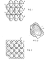
- the product to be canned by means of the apparatus according to the invention is for example constituted by "balls" of ice cream previously conditioned in the form of elementary portions , that is to say solids conforming to the shape of pseudo-hemispherical cells, regularly arranged in length and in width. on “plates” (B) made of sheet plastic. Said cells and, consequently, the "balls” of ice cream have a shape such that they have on one side a circular transverse planar face and on the opposite side the shape of a pseudo-hemispherical cap and a lateral connection face. substantially frustoconical, as shown in particular in Figures 1 and 3.
- the centers of cells A represent the vertices of a square mesh network.
- the length of the side of the base square is chosen so that, taking into account the height of a cell, it can be placed, inverted, between four cells of the adjacent plate so that its lateral face is tangent to each of the lateral faces of said four cells, as shown in FIGS. 1 and 2.
- the number of pairs of plates that can be stacked in the same box can be any number, but the pairs of plates of even rank from the bottom of the box are all offset in the manner indicated above with respect to the pairs of plates. of odd rank.
- each plate can advantageously be of square shape and include nine cells regularly spaced apart in two dimensions, the centers of the circles forming their flat faces thus being arranged at the vertices of the squares forming a network with regular square meshes of nine squares.
- each receiver box can contain, for example, five pairs of two plates each joined by their plane faces, that is to say in total ten plates of nine balls each, the pairs of plates of even rank being offset from that of odd rank, along the same diagonal of the square and of a length equal to the half-diagonal of an elementary square.
- the apparatus essentially comprises mounted on chassis 1: a platform 2 on which can move in horizontal rectilinear translation and in both directions, a carriage 3 forming a support for two plates 4 and 5 platelet receptors; an assembly 6 for cutting said wafers, and for evacuating the latter in a box, below and plumb with which the two said trays loaded with a wafer are placed alternately; a plate 7 forming a support for the boxes, which cooperates with a mechanism which causes it to descend step by step as and when the plates are stacked in the receiving box; and, a set of means for closing and evacuating the filled boxes.
- a carriage 3 On the horizontal platform 2 can move by means of guide members of any suitable known type, a carriage 3 on which are arranged at each of its two ends, the two plates 4 and 5.
- Each of these two trays 4 and 5 is shaped to receive such wafers, the cells of which have been previously filled with ice cream. To this end, it includes as many cells for receiving cells as there are cells in a wafer of ice cream "balls", that is to say nine in this case and arranged in the same way as said cells as shown in Figure 6.
- the two plates which are integral with the carriage move at the same time as it in horizontal translation, straight bars or rails 2a and 2b forming a guide for rollers 3a and 3b integral with the carriage constituting, for example, the bodies of guiding this movement.
- the device is assumed to be viewed from the front, that is to say as shown in FIG. 4, so that the plate 4 is the plate on the left and the plate 5 is the plate on the right.
- This horizontal translation movement takes place between two extreme positions, sometimes from the right to the left, sometimes from the left to the right, and in such a way that, when the left plate 4 is in the extreme position, it is in the receiving position of a plate of "balls", while the right plate 5 previously loaded with a plate is directly above the assembly 6 for cutting and evacuating the plates. Similarly, when the right tray is in the extreme position, the left tray previously loaded with a wafer, is plumb with the cutting assembly.
- each of the plates 4 and 5 is mounted in a known manner on two slides 5a which are integral with it and cooperate with, for example, guide rods 5b fixed relative to the carriage, as shown in FIG. 6.
- both of the carriage and of the plates are obtained by means, for example, of jacks (not shown), the ends of the rods of which are made respectively integral both with the carriage and with each of the two plates, said movements being coordinated with each other by means of any suitable known device, and as described below.
- the plates situated on the same side of the carriage are loaded, for example manually, so that the concavity of the cells of the plates placed on a plate are always oriented in the same direction, and the concavity of the cells of the plates, placed in place on the plate opposite to the previous one are oriented in the opposite direction.
- the cells of the wafers placed on the right tray always have their concavity turned upwards, said cells thus being housed on the tray so that each of them is placed in a box of the corresponding tray, while that the cells of the wafers placed on the left plate are arranged so that their concavity is turned downwards, said cells then having their flat face arranged opposite the boxes of the corresponding plate.
- the plates are provided with lateral claws for retaining the plates which are placed there, and the positioning of which is controlled automatically upon setting in motion, in order to avoid any unwanted displacement of the latter.
- the plates pre-cut and whose cells have been filled, with ice cream, in the solid state, are placed on the plates 4 and 5 as just indicated, said plates occupying the same extreme position on the carriage.
- the carriage in a first phase, is moved so that the right plate comes to be placed directly above the assembly 6 for cutting the wafers and that, as explained below, it can be discharged through a member of this set m m e - 6 in a receiving box.
- the carriage is moved in the opposite direction to the previous one until the left plate comes to place itself in line with the assembly 6, then after cutting of the wafer which it supports, evacuated by means of the ejection members associated with the cutting device in the receiving box, directly above the wafer which has been previously arranged there, the two wafers then being exactly symmetrical l ' one of the other, compared to the common plane by which they face each other.
- the device for cutting and ejecting the elementary portions of cut wafers is mounted on the carriage so that it is kept stationary during the overall movement of the carriage and that it can, on the contrary, move obliquely relative to the direction of the latter at the same time as the two plates, so that it is always plumb with one or the other plate, in the cutting phase.
- the plate 7, which, as indicated below in more detail, is integral with a column 8 formed of two support rods, is movable between two extreme positions, one upper, the other lower.
- the boxes 9 for receiving the wafers which, most often are made of a material capable of supporting folding along. rectilinear parts, such as for example cardboard, have a square cross section so that two successive plates placed in staggered rows with respect to each other each bear on two of their adjacent sides on the internal wall of the corresponding box.
- the plate 7 is located at level 10 of an evacuation device (not shown) of the filled box.
- edges 9a, 9b, 9c, and 9d of the upper part of the box 9 are folded down along the corresponding external lateral faces of the latter and held in this position as follows: the edges 9a and 9b are kept folded down respectively by the edge 9b of the empty box preceding the box to be filled and by the edge 9a of the box which has just been filled, while the edges 9c and 9a are kept folded down by and between flanges 11a and 11b integral with the machine frame.
- edges 9e, 9f, 9g and 9h of the lower part of the box are folded outwards at 90 °, have their internal faces applied on the upper face of level 10 and are held by means of the angles 12a and 12b secured to the frame of the machine, while the edges 9g, 9h are folded outwardly and maintained, like the corresponding edges of the upper part of the box, by the lower edges of the adjacent boxes.
- the plate 7 When the box ready to be filled has been thus placed, the plate 7, is raised from level 10 in the manner indicated below, until it is flush with the upper contour of the box as shown in Figures 4 and 5; the box is then ready to receive the layers of platelets for their installation, after cutting into elementary portions, with the staggered arrangement as described above.
- the right tray On which the ball plates are placed so that the concavity of their cells faces upwards, is brought loaded directly above the cutting assembly 6 and ejection of said plates.
- This assembly 6 essentially comprises, mounted on the upper part of the chassis 1, at least one, but preferably two cylinders 13a and 13b, fluid under pressure, for example hydraulic, with vertical longitudinal axes, and whose rods, placed on the bottom side, have their ends rigidly secured to a cutting block 14.
- the latter comprises two groups of pairs of blades arranged parallel to each other and regularly spaced; the two parallel blades of a pair, the cutting edges of which are at the same level, have a length equal to that of the side of the square forming the outline of a compartment of a platelet receiving tray and cover the parts of the platelets not affected by the precut between two adjacent cells.
- the planes containing the blades of the first group are perpendicular to the direction of movement of the carriage 3, while the planes containing the blades of the second group are parallel to the direction of movement of this same carriage. Furthermore, this cutting block is provided on each of its four sides with two guide rods.
- each of the pairs of the cutting block is then placed directly above a partition separation of the cells, a blade of each pair then being plumb with a partition dividing two adjacent boxes of the corresponding tray.
- each of the upper parts of the partitions dividing the cells of the platelet receiving tray comprises, opposite the corresponding blade, a cavity of complementary shape of this same blade over a certain depth, into which the coresponding blade can sink, after having crossed the wafer and having made the cutting notch there.
- the corresponding simultaneous vertical movements of the different blades are caused by the simultaneous extensions of the rods of the cutting cylinders 13a and 13b.
- the wafer is then cut into nine parts or elements of general square contour each comprising a cell, these elements no longer resting then by the edge of their contour on the walls of the corresponding box of the receiving tray 4 or 5.
- the set 6 for cutting the plates further comprises a tool for ejecting the portions of square contour plates resting on the plate 7 where they have been cut out of this plate.
- This tool is constituted by a set of ejectors 16 formed by pushers integral with a common support 17 arranged on this support respectively opposite the cells.
- the support for the ejectors is made integral with the end of the rod of an actuator 18 integral with a frame of longitudinal axis parallel to the longitudinal axes of the actuating cylinders for cutting tools for the inserts on the plates, said actuator being placed at a height such that the distance separating the point of its course corresponding to the contact of the free end of an ejector with the corresponding ice cream cell and the point of its race corresponding to that where said cell was ejected of the tray and pushed back into the box is equal to the height of a cell, the level at which the vertices of the nine cells alternately or their flat face being that of the orifice of the ball receiving box.
- This ejection operation and introduction into the receiving box 9 of the nine cells simultaneously is made possible by the fact that the support material for the ice cream balls provided with such cells is a flexible sheet material and elastic at the same time.
- the edges of the nine cavities forming the nine cells filled with ice cream which, before the ejection rested on the edge of the square contour cavities of the corresponding platelet receiving tray, fold back under the effect of the thrust of the ejection corespondant thanks to their flexibility, which allows them to cross folded said cavities by resting on the inner faces of the latter, and to resume thanks to their elasticity their initial planar shape once this crossing made.
- the plate of the ice cream scoop is pushed down the height of a cell in the manner indicated below.
- the square tray 7 receiving boxes 9 is supported in its central region by an olonnne 8 formed by a set of two vertical rods 19 of the same length.
- These rods 19 are interconnected by bars 20 forming notches regularly staggered together and the number of which is at least equal to the number of layers of balls stacked in staggered rows in a box.
- these rods are guided in vertical axial translation by means of at least two groups of two rollers 21 each carried by yokes 22 made integral with the chassis of the device by any suitable known means.
- each group of two guide rollers the rollers which can rotate freely around their axes are placed so that they are opposite to each other, their grooves or raceway bearing on the outer lateral faces of the rods 19, that is to say those opposite the inner side faces connected together by the bars 20 and can rotate without sliding when the rods move.
- the two rods 19 are secured to each other at their ends by a spacer plate 23.
- the two rods 19 are also in permanent contact with a brake, the two jaws 24 and 25 of which bear by their internal faces respectively on the two rods 20.
- These jaws are joined together by two rods 26 and 27 secured to the chassis.
- the device and arranged horizontally and parallel to the vertical plane containing the vertical axes of the rods 20. At least one of these two jaws can slide along the support rods, the other being kept pressed on the corresponding rod 20, the jaw sliding then being pressed against the corresponding rod by any suitable known means by means of a compressible elastic member, for example a compressible spring bearing directly or indirectly on the one hand on the jaw and, on the other hand, on the device chassis.
- each of the two jaws can be mounted so as to bear on the corresponding rod by means of a compressible spring.
- the mechanical characteristics of the compression springs are chosen such that. the friction forces exerted in contact with the jaws and the rods are sufficient to prevent the descent against these forces under the effect of its own weight of the assembly formed by the plate .7, the rods 19 and their connecting elements 20 and 23 as well as the weight of the total maximum load of the platform 7, but that, on the other hand, this descent can be obtained by means of a thrust of appropriate value added to the weight of this assembly, as for example, the thrust exerted by the actuator for ejecting the ice cream scoops out of their support plate, this movement of descent of the plate 7 and of all the elements which are linked to it ceasing as soon as this thrust ceases.
- a pawl 28 articulated around an axis 29 parallel to the rods 26 and 27 forming their supports.
- This pawl comprises on one side of the axis 28, one end cooperating with the various bars 20 as the descent of the packaging carrier plate 7 and on the other side of this same axis a connected end 28b, by means of an elastic extensible member, for example, a spring 30, to a ratchet clevis 31, also articulated around the axis 29 of said pawl.
- This yoke cooperates with the rod 32 of a jack 33 secured to the chassis of the apparatus for its maintenance in a fixed position during the downward movement of the plate 7, a housing being provided for this purpose for the end of the rod of said cylinder.
- the ratchet yoke comprises, on its face opposite to the rods 19 tray holder 7 and on the other side of its axis 29 relative to these same rods, a part provided with a fork 34 with two branches, open on the side opposite to said rods 19, the role of which will be explained later.
- the device for lowering the plate 7 as described above further comprises a vertical pendulum 35 articulated around a horizontal axis parallel to the axis of rotation 29 of the pawl, integral with the chassis of the apparatus and disposed at a level lower than that of said axis 29.
- This balance comprises, at its upper end, a ratchet guide formed by a cylindrical rod 35a, which is engaged in the fork 34 of the ratchet yoke, when said balance is. in vertical rest position.
- This balance comprises, in addition, at its lower end a roller 35b whose axis of rotation, parallel to its own axis of oscillation is eccentric with respect to it and disposed on the side of the rods 19, the axis of said roller being secured to the balance rod via a yoke 35c which is made integral with any suitable known means, for example, by welding.
- the balance rod is connected to the chassis of the device by an elastic elastic member 36 which urges it under traction, so that naturally and apart from any other constraint, the part of said pendulum placed above its axis of rotation is attracted to the side of this chassis, that is to say moves away from the rods 19, this displacement remaining however limited by a length stop adjustable 37, while the part situated above this axis, and consequently, the roller 35b, approaches it, the pawl guide then not being, in this position, no longer engaged with the pawl yoke by the fork 34.
- This part of the device finally comprises a jack 38 whose body is secured to the frame by any suitable known means and whose rod 38a, provided at its end with a pusher 38b is extendable downwards and retractable upwards.
- Said pusher cooperates on the one hand, by its plate when the cylinder rod is in the extended position, with the roller 35b to maintain the balance in the vertical position, which has the effect of returning, by means of the ratchet guide 35a, the clevis of the pawl in the working position and thus obtain the locking, by means of the rod 32, of the jack 33, and, on the other hand, also by this same plate, with the spacer plate of the rods 19 to reassemble the said rods and consequently the plate 7, when, after its descending movements in successive steps, it is lowered by a height equal to that of its stroke, which corresponds to the height of a box 9.
- the rod of the jack 38 returns as indicated below, in position extension, position in which, after having attacked the roller 35b of the pendulum 35, the pusher 38b brings it back then maintains it in the vertical position, which has the effect of bringing the ratchet yoke and, consequently, the ratchet in position working position in which the end of the rod 32 of the jack 33 is placed in the housing provided for this purpose in the ratchet yoke to keep it fixed throughout the duration of the new descent of the plate 7.
- the reception box At the end of the descent of the plate 7, that is to say when the reception box is filled, it is pushed out of the plate onto a packaging machine, by an empty box which then takes its place on the tray, a jack whose end of the rod is provided with a pusher being provided for this purpose, and the empty box in turn pushing the full box.
- control of the running and / or stopping of the various pressurized fluid cylinders ensuring the movements m ents of the various organs described above and the coordination of said movements is obtained by means of any suitable control device of known type which can implement various means, for example, electrical, electronic, electromagnetic, mechanical, pneumatic or a combination of these various means.
- the spacer 23 connecting the rods 19 forms the support of a part provided with cams cooperating with a movable member, along which said cams travel as the descent of the plate 7.
- the support of said cams is constituted, for example, by a square-shaped piece 39 having as plane of symmetry the vertical plane containing the longitudinal axes of the two rods 29, fixed by any suitable known means, by its horizontal branch 39a to the spacer 23, while its vertical branch 39b, at the free upper end, is provided with cams constituted, for example, by a series of notches 39c and redents 39d regularly spaced apart over part of the height of said upper end and cooperating with a roller 40 movable both in rotation about its axis and in rotation around an axis of rotation parallel to the previous one, fixed relative to the chassis, the link arm of the yoke of the roller to this axis being constrained by a .organ elastic return, so that the roller finds its natural position in the notches 39c and the spring is constrained when the roller is pushed on a redent 39d between two notches 39c.
- This laision arm is integral with closing (and opening) members of the control circuits of the various members of the apparatus, which therefore
- the control member of the actuator 1 3 controls the starting of its rods 13a and 13b, an operation which results in the complete cutting of the precut plate. in place on the tray 5.
- This operation causes said balls to pass through the tray, a push and a descent of the tray 7 on which the first layer of balls then rests inside the box 9 previously put in place, over a height equal to the height separating the plane of the flat face of a plate from that of the flat face of one of the two plates which are adjacent to it in the stacking of the box.
- the control circuits of the organs of the apparatus are chosen in such a way that in this new position, the actuators for controlling the oblique translation of the assembly of the carriage 2 tray holders and of the assembly 6 for cutting and ejection of the ice cream balls linked to the previous one, move the said sets in a direction inclined at 45 ° in the direction of movement of the plates 4 and 5 on the carriage and over a length equal to half the length of a diagonal of the square formed by the centers of four adjacent cells two by two on the same wafer.
- the right-hand plate 5 which was loading during the previous operation of introducing the second wafer into the receiving box, is then brought into line with the cutting assembly, the wafer which it supports having on this right tray the same orientation as that of the wafer which was previously supported by the same tray.
- the box arranged in two sets of two layers each, in each of which the flat face of a cell of one is opposite that of a cell of the other, the two so-called layers, which are identical, being offset from each other along a diagonal of the square forming the outline of initial plates and of a length equal to the half-diagonal of the square having for vertices the centers of four adjacent cells two by two.
- the roller cooperating with the camshaft is in the same position as that in which it was at the end of the first cycle; therefore, the circuit for controlling the translation of the assembly formed by the carriage 2 tray carriers. 4 and 5 and by the cutting and ejection assembly which is integral therewith is placed in the closed position which has the effect of bringing these two assemblies linked to the position they occupied at the start of the first cycle, in which the outline of the wafer-holding trays is then, directly above the outline of the first layer of two wafers pressed into the reception box.
- the sequence of operations described with regard to the first two layers of platelet portions is repeated once more and continues automatically, until a predetermined number of layers, for example five (this which corresponds to the boxing of ten layers of portions of ball platelets in total) has been stored in the box.
- a predetermined number of layers for example five (this which corresponds to the boxing of ten layers of portions of ball platelets in total) has been stored in the box.
Abstract
Description
La présente invention concerne un appareil : mise en boite à partir de plaques prédécoupées formant le support d'un produit, par exemple de la crème glacée à basse température, remplissant des alvéoles pseudo-hémisphérique méénagés sur lesdites plaques, et de disposition en quinconce des ces dernières desdites plaques à l'intérieur de ladite boite.The present invention relates to an apparatus : canning from precut plates forming the support of a product, for example ice cream at low temperature, filling pseudo-hemispherical cells arranged on said plates, and staggered arrangement of the latter of said plates inside said box.
On sait depuis longtemps juxtaposer et disposer en. quinconce des objets à corps rond identiques entre eux. Ces objets sont généralement des bouteilles ou des boites cylindriques dont le fond, sensiblement plan et circulaire repose sur un plateau ou le fond horizontal d'une caisse ou d'un carton d'emballage. Juxtaposés de cette manière, ces objets se calent mutuellement, occupent alors la surface la plus faible possible, ce qui a pour effet, d'une part, de réduire l'encombrement, de faciliter les opérations de manutention, et, d'autre part, de réduire l'importance ces emballages.We have known for a long time to juxtapose and dispose of. stagger objects with identical round bodies between them. These objects are generally cylindrical bottles or cans, the bottom, substantially planar and circular rests on a tray or the horizontal bottom of a box or a cardboard packaging. Juxtaposed in this way, these objects wedge each other, then occupy the smallest possible surface, which has the effect, on the one hand, of reducing the bulk, of facilitating the handling operations, and, on the other hand , reduce the importance of this packaging.
Pour réaliser de telles opérations de rengement en. quinconce, il existe au moins deux sortes de machines. L'une d'entre elles est plus spécialement adaptée au condi- ticonnement de bouteilles et possède, à cet effet, ces pinces perrmettant d'en saisir le goulot de diamètre plus faible que soin corps pour l'amener dans la position qui lui est assignée dams l'ensemble. Une machine de ce type est coûteuse et compliquée et elle ne peut être commodément employée pour la juxtaposition en quinconce d'objets tels que des boites de conserve, à cause de l'encombrement des pinces. Une autre machine, adaptée à de nombreuses formes particulières d'objets à corps rond, les dispose par files guidées dans des couloirs, forme des files juxtaposées dont elle décale ensuite une sur deux d'un demi-diamètra, puis applique aux filles décalées une poussée transversale pour accoler les objets.To carry out such re-farming operations in. staggered, there are at least two kinds of machines. One of them is more specially adapted for the packaging of bottles and has, for this purpose, these clamps allowing to grasp the neck of smaller diameter than body care to bring it into the position which it is assigned to the whole. A machine of this type is expensive and complicated and it cannot be conveniently used for staggered juxtaposition of objects such as cans, because of the size of the clamps. Another machine, adapted to many particular forms of objects with a round body, arranges them by guided lines in corridors, forms juxtaposed lines which it then shifts one in two by half a diameter, then applies to the offset girls a transverse thrust to attach objects.
Toutefois, une telle machine ne permet pas de procéder au rangement en quinconce, de tous les objets à corps rond suivant les trois dimensions.However, such a machine does not allow staggered storage of all round-body objects according to the three dimensions.
La présente invention obvie à cette insuffisance en fournissant un appareil de mise en boite suivant les trois dimensions d'objets à corps rond et plus particulièrement d'objets pseudo-hémisphériques présentant une face plane et logés dans des alvéoles ménagés sur des plaquettes prédécoupées. De tels objets peuvent être, par exemple, des boules de crème glacée déjà solidifiée.The present invention overcomes this insufficiency by providing a boxing device according to the three dimensions of objects with a round body and more particularly pseudo-hemispherical objects having a flat face and housed in cells formed on precut plates. Such objects may be, for example, already solidified ice cream scoops.
L'appareil selon l'invention est essentiellement caractérisé par lè fait qu'il comporte : une plate-forme formant support d'un chariot, sur lequel sont montés deux plateaux de réception de plaquettes prédécoupées et mobile en translation horizontale alternativement entre deux positions extrêmes correspondant l'une à une position de chargement, et l'autre à une position de découpage desdites plaquettes en portions élémentaires et d'éjection desdites portions, lesdits plateaux étant eux-mêmes mobiles en translation horizontale par rapport au chariot suivant une direction inclinée à 45° par rapport à la direction de translation dudit chariot entre deux positions extrêmes séparées par une distance égale à la demi-diagonale du carré formé en joignant les centres de quatre alvéoles contigus ; un plateau horizontal de réception des couches successives de portions élémentaires de plaquettes ainsi découpées, mobile en translation verticale alternativement entre deux positions extrêmes, la translation ascendante étant réalisée de manière continue, tandis que la translation descendante, est réalisée, par pas successifs, à l'intérieur d'un emballage le long des parois internes duquel il se déplace ; et un dispositif de commande dudit plateau de réception coopérant avec un ensemble d'organes de commande et de coordination automatique des différents mouvements de l'ensemble de l'appareil.The apparatus according to the invention is essentially characterized by the fact that it comprises: a platform forming a support for a carriage, on which are mounted two plates for receiving pre-cut wafers and movable in horizontal translation alternately between two extreme positions one corresponding to a loading position, and the other to a position for cutting said plates into elementary portions and ejecting said portions, said plates themselves being movable in horizontal translation relative to the carriage in a direction inclined to 45 ° relative to the direction of translation of said carriage between two extreme positions separated by a distance equal to the half-diagonal of the square formed by joining the centers of four contiguous cells; a horizontal plate for receiving the successive layers of elementary portions of wafers thus cut, movable in vertical translation alternately between two extreme positions, the upward translation being carried out continuously, while the downward translation, is carried out, in successive steps, at the inside a package along the internal walls of which it moves; and a device for controlling said receiving plate cooperating with a set of control and automatic coordination members for the various movements of the entire device.
Les caractéristiques et avantages de l'invention ressortiront mieux de la description faite ci-après à titre d'exemple non limitatif et en regard des dessins annexés sur lesquels :
- - la figure 1 représente une vue de côté d'un empilage de plaquettes de "boules" de produit tel qu'il se présente dans une boite réceptrice ;
- - la figure 2 représente l'empilage de la figure 1 vu de dessus ; ,
- - la figure 3 représente une vue en perspective d'une portion de plaquette après découpage et telle qu'ensuite emballée, et montrant l'alvéole de réception du produit ;
- - la figure 4 représente une vue d'ensemble de face de l'appareil selon l'invention ;
- - la figure 5 représente une vue d'ensemble de côté de l'appareil de la figure 4 ; et
- - la figure 6 représente une vue de dessus du chariot porte-plateaux de l'appareil des figures 5 et 6.
- - Figure 1 shows a side view of a stack of platelets of "balls" of product as it occurs in a receiving box;
- - Figure 2 shows the stack of Figure 1 seen from above; ,
- - Figure 3 shows a perspective view of a portion of wafer after cutting and as then packaged, and showing the cell for receiving the product;
- - Figure 4 shows an overall front view of the apparatus according to the invention;
- - Figure 5 shows an overall side view of the apparatus of Figure 4; and
- FIG. 6 represents a top view of the trolley carrying the trays of the apparatus of FIGS. 5 and 6.
Sur ces différentes figures, les mêmes références représentent les mêmes éléments.In these different figures, the same references represent the same elements.
En se référant tout d'abord aux figures 1, 2 et 3, le produit à mettre en boites au moyen de l'appareil selon l'invention est par exemple constitué par des "boules" de crème glacée préalablement conditionnées sous forme de portions élémentaires, c'est-à-dire de solides épousant la forme d'alvéoles (A) pseudo-hémisphériques, disposés régulièrement en longueur et en largeur.sur des "plaquettes" (B) réalisées en une matière plastique en feuille. Lesdits alvéoles et, par suite, les "boules" de crème glacée ont une forme telle qu'elles présentent d'un côté une face plane transversale circulaire et du côté opposé la forme d'une calotte pseudo-hémisphérique et une face latérale de raccordement sensiblement tronconique, comme représenté en particulier sur les figures 1 et 3. Les centres des alvéoles A représentent les sommets d'un réseau à maille carrée. La longueur du côté du carré de base est choisie de telle manière que, compte tenu de la hauteur d'un alvéole, celui-ci puisse être placé, renversé, entre quatre alvéoles de la plaque adjacente de manière que sa face latérale soit tangente à chacune des faces latérales desdits quatre alvéoles, comme représenté sur les figures 1 et 2. De cette manière, il est possible d'empiler les uns sur les autres des ensembles de deux plaquettes dont les faces planes coïncident, chaque paire de plaquettes ainsi constituée étant décalée de la précédente de manière à former un empilement en quinconce dans les trois dimensions. Le nombre des paires de plaquettes que l'on empile dans une même boite peut être quelconque mais, les paires de plaquettes de rang pair à partir du fond de la boite sont toutes décalées de la manière ci-dessus indiquée par rapport aux paires de plaquettes de rang impair.Referring first to Figures 1, 2 and 3, the product to be canned by means of the apparatus according to the invention is for example constituted by "balls" of ice cream previously conditioned in the form of elementary portions , that is to say solids conforming to the shape of pseudo-hemispherical cells, regularly arranged in length and in width. on "plates" (B) made of sheet plastic. Said cells and, consequently, the "balls" of ice cream have a shape such that they have on one side a circular transverse planar face and on the opposite side the shape of a pseudo-hemispherical cap and a lateral connection face. substantially frustoconical, as shown in particular in Figures 1 and 3. The centers of cells A represent the vertices of a square mesh network. The length of the side of the base square is chosen so that, taking into account the height of a cell, it can be placed, inverted, between four cells of the adjacent plate so that its lateral face is tangent to each of the lateral faces of said four cells, as shown in FIGS. 1 and 2. In this way, it is possible to stack on top of each other sets of two plates whose plane faces coincide, each pair of plates thus formed being offset from the previous one so as to form a staggered stack in three dimensions. The number of pairs of plates that can be stacked in the same box can be any number, but the pairs of plates of even rank from the bottom of the box are all offset in the manner indicated above with respect to the pairs of plates. of odd rank.
Ainsi, par exemple, chaque plaquette peut avantageusement être de forme carrée et comporter neuf alvéoles régulièrement espacés entre eux dans les deux dimensions, les centres des cercles formant leurs faces planes étant ainsi disposés aux sommets des carrés formant un réseau à mailles carrées régulières de neuf carrés. Avantageusement, dans ce cas, chaque boîte réceptrice peut contenir par exemple, cinq paires de deux plaquettes chacune accolées par leurs faces planes, c'est-à-dire au total dix plaquettes de neuf boules chacune, les paires de plaquettes de rang pair étant décalées par rapport à celle de rang impair, le long d'une même diagonale du carrée et d'une longueur égale à la demi-diagonale d'un carré élémentaire.Thus, for example, each plate can advantageously be of square shape and include nine cells regularly spaced apart in two dimensions, the centers of the circles forming their flat faces thus being arranged at the vertices of the squares forming a network with regular square meshes of nine squares. Advantageously, in this case, each receiver box can contain, for example, five pairs of two plates each joined by their plane faces, that is to say in total ten plates of nine balls each, the pairs of plates of even rank being offset from that of odd rank, along the same diagonal of the square and of a length equal to the half-diagonal of an elementary square.
Comme représenté sur les figures 4, 5 et 6, l'appareil comporte essentiellement monté sur châssis 1 : une plate-forme 2 sur laquelle peut se déplacer en translation rectiligne horizontale et dans les deux sens, un chariot 3 formant support de deux plateaux 4 et 5 récepteurs de plaquettes ; un ensemble 6 de découpage desdites plaquettes, et d'évacuation de ces dernièrs dans une boite, en dessous et à l'aplomb duquel les deux dits plateaux chargés d'une plaquette viennent alternativement se placer ; un plateau 7 formant support des boites, lequel coopère avec un mécanisme qui en provoque la descente pas par pas au fur et à mesure que les plaquettes sont empilées dans la boite réceptrice ; et, un ensemble de moyens de fermeture et d'évacuation des boites remplies.As shown in FIGS. 4, 5 and 6, the apparatus essentially comprises mounted on chassis 1: a
Sur la plate-forme horizontale 2 peut se déplacer au moyen d'organes de guidage de tout type connu approprié, un chariot 3 sur lequel sont disposés à chacune de ses deux extrémités, les deux plateaux 4 et 5. Chacun de ces deux plateaux 4 et 5 est conformé pour recevoir de telles plaquettes dont les alvéoles ont été préalablement remplis de crème glacée. Il comporte à cet effet, autant de cases de réception des alvéoles qu'il y a d'alvéoles dans une plaquette de "boules" de crème glacée, soit neuf dans le cas présent et disposées de la même manière que lesdits alvéoles comme représenté sur la figure 6. Les deux plateaux qui sont solidaires du chariot se déplacent en même temps que lui en translation horizontale, des barres ou rails rectilignes 2a et 2b formant guide pour des galets 3a et 3b solidaires du chariot constituant, par exemple, les organes de guidage de ce mouvement.On the
Dans ce qui suit, l'appareil est supposé être regardé de face, c'est-à-dire comme représenté à la figure 4 si bien que le plateau 4 est le plateau de gauche et le plateau 5 le plateau de droite.In what follows, the device is assumed to be viewed from the front, that is to say as shown in FIG. 4, so that the
Ce mouvement de translation horizontale s'effectue entre deux positions exrêmes, tantôt de la droite vers la gauche, tantôt de la gauche vers la droite, et de telle manière que, lorsque le plateau de gauche 4 se trouve dans la position extrême, il soit en position de réception d'une plaquette de "boules", tandis que le plateau de droite 5 préalablement chargé d'une plaquette se trouve à l'aplomb de l'ensemble 6 de découpage et d'évacuation des plaquettes. De même, lorsque le plateau de droite se trouve dans la position extrême, le plateau de gauche préalablement chargé d'une plaquette, se trouve à l'aplomb de l'ensemble de découpage.This horizontal translation movement takes place between two extreme positions, sometimes from the right to the left, sometimes from the left to the right, and in such a way that, when the
Outre le mouvement de translation rectiligne horizontale alternatif d'entraînement par le chariot qui les supporte, les deux plateaux sont montés sur celui-ci de manière à pouvoir se mouvoir simultanément par rapport à lui suivant un mouvement de translation rectiligne horizontale alternatif entre deux positions extrêmes et dont la direction fait avec celle du mouvement de chariot un angle de 45°, l'amplitude de ce mouvement relatif ayant une valeur égale à celle de la demi-diagonale du carré formant une maille élémentaire du réseau suivant lequel se répartissent les alvéoles d'une plaquette. A cet effet, chacun des plateaux 4 et 5, est monté de manière connue sur deux coulisseaux 5a qui en sont solidaires et coopèrent avec, par exemple, des tiges de guidage 5b fixes par rapport au chariot, comme repréenté sur la figure 6. Ces différents mouvements de translation, tant du chariot que des plateaux sont obtenus au moyen par exemple, de vérins (non représentés), dont les extrémités des tiges sont rendues solidaires respectivement tant du chariot que de chacun des deux plateaux, lesdits mouvements étant coordonnés entre eux au moyen de tout dispositif connu approprié, et de la manière décrite plus loin. Les plateaux situés d'un même côté du chariot sont chargés, par exemple manuellement, de manière que la concavité des alvéoles des plaquettes mises en place sur un plateau soient orientées toujours dans le même sens, et que la concavité des alvéoles des plaquettes, mises en place sur le plateau opposé au précédent soient orientées en sens contraire. Ainsi, par exemple, les alvéoles des plaquettes placées sur le plateau de droite ont toujours leur concavité tournée vers le haut, lesdits alvéoles venant ainsi se loger sur le plateau de manière que chacun d'eux soit placé dans une case du plateau correspondant, tandis que les alvéoles des plaquettes mises en place sur le plateau de gauche sont disposés de façon que leur concavité soit tournée vers le bas, lesdits alvéoles ayant alors leur face plane disposée en regard des cases du plateau correspondant. Avantageusement, les plateaux sont munis de griffes latérales de retenue des plaquettes qui y sont placées, et dont la mise en place est commandée automatiquement à la mise en mouvement, afin d'éviter tout déplacement non souhaité de celles-ci.In addition to the reciprocating horizontal rectilinear translational movement by the carriage which supports them, the two plates are mounted on the latter so as to be able to move simultaneously with respect to it in an alternating horizontal rectilinear translational movement between two extreme positions. and whose direction makes with that of the carriage movement an angle of 45 °, the amplitude of this relative movement having a value equal to that of the half-diagonal of the square forming an elementary mesh of the network along which the alveoli of a wafer. To this end, each of the
Les plaquettes, préalablement prédécoupées et dont les alvéoles ont été remplis, de crème glacée, à l'état solide, sont placées sur les plateaux 4 et 5 comme il vient d'être indiqué, lesdits plateaux occupant sur le chariot la même position extrême. Le chariot, dans une première phase, est déplacé de manière que le plateau de droite vienne se placer à l'aplomb de l'ensemble 6 de découpage des plaquettes et que, comme expliqué plus loin, il puisse être évacué par un organe de ce mëme ensemble - 6 dans une boite réceptrice. A l'issue de ces opérations et dans une seconde phase, le chariot est déplacé en sens inverse du précédennt jusqu'à ce que le plateau de gauche vienne se placer à son tour à l'aplomb de l'ensemble 6, puis après découpage de la plaquette qu'il supporte, évacué au moyen des organes d'éjection associés au dispositif de découpage dans la boite réceptrice, à l'aplomb de la plaquette qui y a été précédemment disposée, les deux plaquettes se trouvant alors exactement symétriques l'une de l'autre, par rapport au plan commun par lequel elles se font alors face.The plates, pre-cut and whose cells have been filled, with ice cream, in the solid state, are placed on the
Au cours du cycle suivant, les mêmes opérations sont répétées, mais les plateaux occupent pendant toute la durée de ce cycle la seconde position extrême qu'ils peuvent avoir par rapport au chariot, c'est-à-dire après une translation suivant un axe incliné à 45° sur la direction de déplacement dudit chariot et sur une longueur égale à la demi-diagonale du carré formant le contour d'une case de plateau, comme ci-dessus déjà mentionné.During the following cycle, the same operations are repeated, but the plates occupy during the entire duration of this cycle the second extreme position that they can have relative to the carriage, that is to say after a translation along an axis inclined at 45 ° to the direction of movement of said carriage and over a length equal to the half-diagonal of the square forming the outline of a tray space, as above already mentioned.
Le- dispositif de découpage et d'éjection des portions élémentaires de plaquettes découpées est monté sur le chariot de façon qu'il soit maintenu immobile lors du déplacement d'ensemble du chariot et qu'il puisse au contraire se déplacer obliquement par rapport à la direction de celui-ci en même temps que les deux plateaux, de manière qu'il se trouve toujours à l'aplomb de l'un ou l'autre plateau, dans la phase de découpage.The device for cutting and ejecting the elementary portions of cut wafers is mounted on the carriage so that it is kept stationary during the overall movement of the carriage and that it can, on the contrary, move obliquely relative to the direction of the latter at the same time as the two plates, so that it is always plumb with one or the other plate, in the cutting phase.
Le plateau 7, qui, comme indiqué plus loin plus en détail est solidaire d'une colonne 8 formée de deux tiges- supports, est mobile entre deux positions extrêmes, l'une supérieure, l'autre inférieure. Les boites 9 de réception des plaquettes qui, le plus souvent sont réalisées en une matière pouvant supporter le pliage le long de. parties rectilignes, comme par exemple du carton, ont une section droite carrée de manière que deux plaquettes successives placées en quinconce l'une par rapport à l'autre prennent chacune appui par deux de leurs côtés adjacents sur la paroi interne de la boite correspondante. A la fin du cycle de remplissage d'une boîte, le platau 7 se trouve au niveau 10 d'un appareil d'évacuation (non représenté) de la boite remplie. Lorsque cette boite a été évacuée, une nouvelle boite vide est poussée à l'aplomb de l'ensemble 6 de découpage, le contour intérieur de la boîte étant alors placé le long du contour extérieur du plateau 9 dont elle épouse la forme. Pour ce faire, les bords 9a, 9b, 9c, et 9d de la partie supérieure de la boîte 9 sont rabattus le long des faces latérales extérieures correspondantes de celle-ci et maintenus dans cette position de la façon suivante : les bords 9a et 9b sont maintenus rabattus respectivement par le bord 9b de la boite vide précédant la boite à remplir et par le bord 9a de la boîte qui vient d'être remplie, tandis que les bords 9c et 9a sont maintenus rabattus par et entre des flasques lla et llb solidaires du bâti de la machine. De la même manière, parmi les bords 9e, 9f, 9g et 9h de la partie inférieure de la boite, les bords 9e et 9f sont repliés vers l'extérieur à 90°, ont leurs faces internes appliquées sur la face supérieure du niveau 10 et sont maintenus au moyen des cornières 12a et 12b solidaires du bâti de la machine, tandis que les bords 9g, 9h sont rabattus extérieurement et maintenus, comme les bords correspondants de la partie supérieure de la boîte, par les bords inférieurs des boîtes adjacentes. Lorsque la boite prête à être remplie a été ainsi placée, le platau 7, est remonté à partir du niveau 10 de la manière indiquée plus loin, jusqu'à ce qu'il affleure le contour supérieur de la boite comme représenté sur les figures 4 et 5 ; la boîte est alors prête à recevoir les couches de plaquettes pour leur mise en place, après découpage en portions élémentaires, avec la disposition en quinconce telle que ci-dessus décrite.The plate 7, which, as indicated below in more detail, is integral with a column 8 formed of two support rods, is movable between two extreme positions, one upper, the other lower. The boxes 9 for receiving the wafers which, most often are made of a material capable of supporting folding along. rectilinear parts, such as for example cardboard, have a square cross section so that two successive plates placed in staggered rows with respect to each other each bear on two of their adjacent sides on the internal wall of the corresponding box. At the end of the filling a box, the plate 7 is located at level 10 of an evacuation device (not shown) of the filled box. When this box has been evacuated, a new empty box is pushed perpendicular to the
Lorsqu'une boite est ainsi disposée, le plateau de droite, sur lequel les plaquettes de boules sont placées de manière que la concavité de leurs alvéoles soit tournée vers le haut, est amené chargé à l'aplomb de l'ensemble 6 de découpage et d'éjection desdites plaquettes.When a box is thus arranged, the right tray, on which the ball plates are placed so that the concavity of their cells faces upwards, is brought loaded directly above the cutting
Cet ensemble 6 comporte essentiellement, montés sur la partie supérieure la du châssis 1, au moins un, mais de préférence deux vérins 13a et 13b, à fluide sous pression, par exemple hydrauliques, d'axes longitudinaux verticaux, et dont les tiges, placées du côté du bas, ont leurs extrémités rigidement solidaires d'un bloc de découpage 14. Celui-ci comporte deux groupes de paires de lames disposées parallèlement entre elles et régulièrement espacées ; les deux lames parallèles d'une paire dontles tranchants sont au même niveau ont une longueur égale à celle du côté du carré formant le contour d'une case d'un plateau de réception des plaquettes et recouvrent les parties des plaquettes non touchées par le prédécoupage entre deux alvéoles adjacents. Les plans contenant les lames du premier groupe sont perpendiculaires à la direction de déplacement du chariot 3, tandis que les plans contenant les lames du second groupe sont parallèles à la direction de déplacement de ce même chariot. Par ailleurs, ce bloc de découpage est muni sur chacun de ses quatre côtés, de deux tiges guides.This
Lorsqu'un plateau du chariot 3 supportant une plaquette dont les alvéoles sont remplis de produit est amené à l'aplomb de l'ensemble 6 de découpage, chacune des paires du bloc de découpage se trouve alors disposée à l'aplomb d'une cloison de séparation des alvéoles, une lame de chaque paire se trouvant alors à l'aplomb d'une cloison de séparation de deux cases adjacentes du plateau correspondant.When a tray of the
Dans cette même position du chariot 3, les tiges guides montées sur le bloc de découpage se trouvent à l'aplomb des encoches en forme de V correspondantes de la plaquette en place sur le plateau placé à l'aplomb de l'ensemble 6. En outre, chacune des parties supérieures des cloisons de séparation des alvéoles du plateau de réception des plaquetes comporte en regard de la lame correspondante une cavité de forme complémentaire de cette même lame sur une certaine profondeur, dans laquelle la lame corespondante peut s'enfoncer, après avoir traversé la plaquette et y avoir fait l'entaille de découpage. Les mouvements verticaux simultanés correspondants des différentes lames sont provoqués par les extensions simultanées des tiges des vérins de coupe 13a et 13b.In this same position of the
Lorsque cette opération de découpage des plaquettes est terminée, la plaquette se trouve alors découpée en neuf parties ou éléments de contour général carré comportant chacune un alvéole, ces éléments ne reposant plus alors que par le bord de leur contour sur les parois de la case correspondante du plateau de réception 4 ou 5.When this cutting operation of the wafers is finished, the wafer is then cut into nine parts or elements of general square contour each comprising a cell, these elements no longer resting then by the edge of their contour on the walls of the corresponding box of the receiving
L'ensemble 6 -de découpage des plaquettes comporte en outre un outil d'éjection des portions de plaquetes de contour carré reposant sur le plateau 7 où elles ont été découpés hors de ce plateau. Cet outil est constitué par un ensemble d'éjecteurs 16 formés par des poussoirs solidaires d'un support commun 17 disposés sur ce support respectivement en regard des alvéoles. Le support des éjecteurs est rendu solidaire de l'extrémité de la tige d'un vérin 18 solidaire dû bâti d'axe longitudinal parallèle aux axes longitudinaux des vérins de manoeuvre des outils de découpage des plaquettes sur les plateaux, ledit vérin étant placé à une hauteur telle que la distance séparant le point de sa course correspondant à la prise de contact de l'extrémité libre d'un éjecteur avec l'alvéole de crème glacée correespondant et le point de sa course.correspondant à celui où ledit alvéole a été éjecté du plateau et repoussé dans la boite soit égale à la hauteur d'un alvéole, le niveau auquel affleurent alternativement les sommets des neuf alvéoles ou leur face plane étant celui de l'orifice de la boite réceptrice des boules. Cette opération d'éjection et d'introduction dans la boite réceptrice 9 des neuf alvéoles simultanément est rendue possible par le fait que la matière support des boules de crème glacée munie de tels alvéoles est une matière en feuille souple et élastique à la fois. Les bords des neuf cavités formant les neuf alvéoles remplis de crème glacée, qui, avant l'éjection reposaient sur le bord des cavités de contour carré du plateau de réception correspondant des plaquettes, se replient sous l'effet de la poussée de l'éjection corespondant grâce à leur souplesse, ce qui leur permet de traverser repliés lesdites cavités en prenant appui sur les faces intérieures de celles-ci, et de reprendre grâce à leur élasticité leur-forme plane initiale une fois cette traversée effectuée.The
Lors de cette opération d'éjection, le platau récepteur des boules de crème glacée est repoussé vers le bas de la hauteur d'un alvéole de la manière ci-après indiquée.During this ejection operation, the plate of the ice cream scoop is pushed down the height of a cell in the manner indicated below.
Le plateau carré 7 récepteur des boites 9 est supporté dans sa région centrale par une olonnne 8 formée par un ensemble de deux tiges verticales 19 de même longueur. Ces tiges 19 sont reliées entre.elles par des barreaux 20 formant crantage régulièrement échelonnés entre eux et dont le nombre est au moins égal au nombre de couches de boules empilées en quinconce dans une boite. En outre, ces tiges sont guidées en translation axiale verticale au moyen d'au moins deux groupes de deux galets 21 chacun porté par des chapes 22 rendues solidaires du châssis de l'appareil par tous moyens connus appropriés. Dans chaque groupe de deux galets-guides, les galets qui peuvent tourner librement autour de leurs axes sont placés de manière qu'ils soient opposés l'un à l'autre, leurs gorges ou chemin de roulement prenant appui sur les faces latérales extérieures des tiges 19, c'est-à-dire à celles opposées aux faces latérales intérieures reliées entre elles par les barreaux 20 et peuvent tourner sans glisser lorsque les tiges se déplacent. Les deux tiges 19 enfin sont solidaires entre elles à leurs extrémités par une plaque entretoise 23.The square tray 7 receiving boxes 9 is supported in its central region by an olonnne 8 formed by a set of two
Les deux tiges 19 se trouvent en outre en contact permanent avec un frein dont les deux mâchoires 24 et 25 prennent appui par leurs faces intérieures respectivement sur les deux tiges 20. Ces mâchoires sont réunies entre elles par deux tiges 26 et 27 solidaires du châssis de l'appareil et disposées horizontalement et parallèlement au plan vertical contenant les axes verticaux des tiges 20. Au moins l'une de ces deux mâchoires peut coulisser le long des tiges support, l'autre étant maintenue appuyée sur la tige 20 correspondante, la mâchoire coulissante étant alors mise en appui contre la tige correspondante par tout moyen connu approprié au moyen d'un organe élastique compressible, par exemple un ressort compressible prenant appui directement ou indirectement d'une part sur la mâchoire et, d'autre part, sur le châssis de l'appareil. Toutefois, chacune des deux mâchoires peut être montée de manière à prendre appui sur la tige correspondante au moyen d'un ressort compressible. Dans un cas comme dans l'autre, les caractéristiques mécaniques des ressorts de compression sont choisies de manière telle que les. forces de frottement s'exerçant au contact des mâchoires et des tiges soient suffisantes pour empêcher la descente à l'encontre de ces forces sous l'effet de son.propre poids de l'ensemble formé par le plateau .7, les tiges 19 et leurs éléments de liaison 20 et 23 ainsi que le poids de la charge maximum totale du plateau 7, mais que, par contre, cette descente puisse être obtenue au moyen d'une poussée de valeur appropriée venant s'ajouter au poids de cet ensemble, comme par exemple, la poussée exercée par le vérin d'éjection des boules de crème glacée hors de leur plateau support, ce mouvement de descente du plateau 7 et de tous les éléments qui lui sont liés cessant dès lors que cesse cette poussée.The two
Entre les deux mâchoires 24 et 25 est disposé un cliquet 28 articulé autour d'un axe 29 parallèle aux tiges 26 et 27 formant leurs supports. Ce cliquet comporte d'un côté de l'axe 28, une extrémité coopérant avec les différents barreaux 20 au fur et à mesure de la descente du plateau 7 porte-emballage et de l'autre côté de ce même axe une extrémité 28b reliée, par l'intermédiaire d'un organe élastique extensible, par exemple, un ressort 30, à une chape 31 porte- cliquet, également articulée autour de l'axe 29 dudit cliquet. Cette chape, coopère avec la tige 32 d'un vérin 33 solidaire du châssis de l'appareil pour son maintien en position fixe pendant le mouvement de descente du plateau 7, un logement étant pévu à cet effet pour l'extrémité de la tige dudit vérin. Par ailleurs, la chape de cliquet comporte, sur sa face opposée aux tiges 19 porte-plateau 7 et de l'autre côté de son axe 29 par rapport à ces mêmes tiges, une pièce munie d'une fourche 34 à deux branches, ouverte sur le côté opposé auxdites tiges 19, dont le rôle sera précisé plus loin. Le dispositif de descente du plateau 7 tel que ci-dessus décrit comporte en outre un balancier vertical 35 articulé autour d'un axe horizontal parallèle à l'axe de rotation 29 du cliquet, solidaire du châssis de l'appareil et disposé à un niveau inférieur à celui dudit axe 29. Ce balancier comporte, à son extrémité supérieure, un guide cliquet formé par une tige cylindrique 35a, laquelle est engagée dans la fourche 34 de la chape de cliquet, lorsque ledit balancier est. en position verticale de repos. Ce balancier comporte, en outre, à son extrémité inférieure un galet 35b dont l'axe de rotation, parallèle à son propre axe d'oscillation est excentré par rapport à lui et disposé du côté des tiges 19, l'axe dudit galet étant solidarisé à la tige du balancier par l'intermédiaire d'une chape 35c qui en est rendue solidaire par tout moyen connu approprié, par exemple, par soudure. Entre le niveau de son axe de rotation et celui de son extrémité supérieure, la tige du balancier est reliée au châssis de l'appareil par un organe élastique extensible 36 qui la sollicite à la traction, si bien que naturellement et en dehors de toute autre contrainte, la partie dudit balancier placée au-dessus de son axe de rotation est attirée du côté de ce châssis, c'est-à-dire s'éloigne des tiges 19, ce déplacement restant toutefois limité par une butée d'arrêt de longueur réglable 37, tandis que la partie située au-dessus de cet axe, et par suite, le galet 35b, s'en rapproche, le guide cliquet n'étant alors, dans cette position, plus en prise avec la chape de cliquet par l'intermédiaire de la fourche 34.Between the two
Cette partie de l'appareil comporte enfin un vérin 38 dont le corps est solidarisé au bâti par tout moyen connu approprié et dont la tige 38a, munie à son extrémité d'un poussoir 38b est extensible vers le bas et rétractable vers le haut. Ledit poussoir coopére d'une part, par sa plaque lorsque la tige du vérin est en position d'extension, avec le galet 35b pour maintenir le balancier en position verticale, ce qui a pour effet de remettre, par l'intermédiaire du guide cliquet 35a, la chape du cliquet en position de travail et obtenir ainsi le verrouillage, au moyen de la tige 32, du vérin 33, et, d'autre part, également par cette même plaque, avec la plaque entretoise des tiges 19 pour remonter lesdites tiges et par suite le plateau 7, lorsque, après ses mouvements de descente par pas successifs, il est descendu d'une hauteur égale à celle de sa course, laquelle correspond à la hauteur d'une boîte 9. Comme expliqué ci-après, la position de la tige du vérin 33 pendant la descente du plateau 7 est sa position d'extension, le balancier étant, de ce fait maintenu vertical pendant toute la durée de ce mouvement de descente, et par suite, le guide-cliquet engagé dans la fourche 34 de la chape de cliquet maintenue fixe par la tige 32 du vérin 33,* jusqu!à ce que l'entretoise 23 vienne prendre contact avec le poussoir 38b, ce qui a pour effet de provoquer presque simultanément le retrait de la tige du vérin 38, la libération du balancier, qui bascule autour de son axe et libère la chape du cliquet, laquelle, basculant à son tour autour de son axe, provoque l'effacement du cliquet, la position d'effacement correspondante étant telle qu'au cours de la remontée du plateau et de ses tiges support 19, les barreaux 20 n'aient aucun contact avec l'extrémité du cliquet, cette remontée étant obtenue par la poussée qu'exerce le poussoir du vérin sur l'entretoise 23 à l'encontre des forces de frottement exercées par le frein sur les tiges 19. En fin de course, la tige du vérin 38 revient comme indiqué plus loin, en position d'extension, position dans laquelle, après avoir attaqué le galet 35b du balancier 35, le poussoir 38b le ramène puis le maintient en position verticale, ce qui a pour effet de ramener la chape de cliquet et, par suite, le cliquet en position de travail, position dans laquelle, l'extrémité de la tige 32 du vérin 33 vient se placer dans le logement prévu à cet effet dans la chape de cliquet pour la maintenir fixe pendant toute la durée de la nouvelle descente du plateau 7.This part of the device finally comprises a
En fin de descente du plateau 7, c'est-à-dire lorsque la boite de réception est remplie, celle-ci est poussée hors du plateau jusque sur une machine à empaqueter, par une boîte vide qui vient alors prendre sa place sur le plateau, un vérin dont-lextrémité de la tige est munie d'un poussoir étant prévu à cet effet, et la boite vide repoussant à son tour la boite pleine.At the end of the descent of the plate 7, that is to say when the reception box is filled, it is pushed out of the plate onto a packaging machine, by an empty box which then takes its place on the tray, a jack whose end of the rod is provided with a pusher being provided for this purpose, and the empty box in turn pushing the full box.
La commande de la marche et/ou de l'arrêt des différents vérins à fluide sous pression assurant les mouve- ments des différents organes ci-dessus décrits et la coordination desdits mouvements est obtenue au moyen de tout dispositif de commande approprié de type connu pouvant mettre en oeuvre des moyens divers, par exemple, électriques, électroniques, électromagnétiques, mécaniques, pneumatiques ou une combinaison de ces divers moyens. A cet effet, l'entretoise 23 reliant les tiges 19 forme le support d'une pièce munie de cames coopérant avec un organe mobile, le long duquel défilent lesdites cames au fur et à mesure de la descente du plateau 7. Le support desdites cames est constituée, par exemple, par une pièce en forme d'équerre 39 ayant comme plan de symétrie le plan vertical contenant les axes longitudinaux des deux tiges 29, fixée par tout moyen connu approprié, par sa branche horizontale 39a à l'entretoise 23, tandis que sa branche verticale 39b, à l'extrémité supérieure libre, est munie de cames constituées, par exemple, par une suite d'échancrures 39c et de redents 39d régulièrement espacés entre eux sur une partie de la hauteur de ladite extrémité supérieure et coopérant avec un galet 40 mobile à la fois en rotation autour de son axe et en rotation autour d'un axe de rotation parallèle au précédent, fixe par rapport au châssis, le bras de liaison de la chape du galet à cet axe étant contraint par un.organe élastique de rappel, de telle manière que le galet trouve sa position naturelle dans les échancrures 39c et que le ressort soit contraint lorsque le galet se trouve repoussé sur un rédent 39d compris entre deux échancrures 39c. Ce bras de laision est solidaire d'organes de fermeture (et d'ouverture) des circuits de commande des différents organes de l'appareil, qui, dès lors, fonctionne comme ci-après indiqué.The control of the running and / or stopping of the various pressurized fluid cylinders ensuring the movements m ents of the various organs described above and the coordination of said movements is obtained by means of any suitable control device of known type which can implement various means, for example, electrical, electronic, electromagnetic, mechanical, pneumatic or a combination of these various means. To this end, the
Un des plateaux, celui de gauche 4, par exemple, chargé d'une plaquette de boules de crème glacée étant supposé se trouver à l'aplomb de l'ensemble de découpage, les alvéoles ainsi remplis étant également supposés présenter leur concavité vers le haut et le plateau récepteur supposé à son niveau le plus élevé, l'organe de commande du vérin 13 commande la mise en marche de ses tiges 13a et 13b, opération qui aboutit au découpage complet de la plaquette prédécoupée en place sur le plateau 5. Une fois cette opération terminée, clest-à-dire lorsque les tiges 13a et 13b ont atteint leur position d'extension complète, l'organe de commande du vérin d'éjection des boules ainsi découpées actionné à son tour, provoque la descente des éjecteurs. Cette opération provoque le passage desdites boules à travers le plateau, une poussée et une descente du plateau 7 sur lequel repose alors la première couche de boules à l'intérieur de la boite 9 préa- lablment mise en place, sur une hauteur égale à la hauteur séparant le plan de la face plane d'une plaquette de celui de la face plane de l'une des deux plaquettes qui lui sont adjacentes dans l'empilage de la boite. Le déplacement vers le bas du plateau 7 de cette hauteur provoque le déplacement vers le bas sur la même hauteur de la tige à cames 39b, si bien que le galet qui coopère avec elle vient en fin de parcours prendre place dans la première des échancrures 39c, ce qui a pour effet de provoquer en même temps que l'ouverture du circuit de commande précédemment fermé, l'ouverture du circuit de commande de la phase suivante des opérations, à savoir le retrait des tiges des vérins de découpage et d'éjection, et la translation de la gauche vers la droite, du chariot porte-plateaux 4 et 5, translation qui amène le plateau de droite 5 à l'aplomb de l'ensemble de découpage et d'éjection, ce plateau ayant été chargé, manuellement ou mécaniquement pendant l'opération précédente avec une plaquette dont les alvéoles sont tournés en sens contraire des alvéoles de la plaquette précédemment découpée et éjectée, de manière qu'une fois en place dans la boite réceptrice, les deux plaquettes se trouvent en contact par leurs faces planes et que les portions élémentaires de plaquettes de l'une et l'autre couche se trouvent ainsi en contact deux à deux par leur face plane. Lorsque ces différents organes arrivent ainsi dans les positions respectivement indiquées, un contact de fin de course du vérin d'entraînement du chariot en translation provoque à la fois l'arrêt de celui-ci et l'ouverture du circuit de commande des vérins de découpage et les mêmes opérations que celles ci-dessus indiquées se reproduisent et se déroulent de la même manière, le plateau de droite étant, à son tour et pendant leur durée, chargé d'une plaquette de boules disposée de la même manière que la plaquette précédemment placée sur le plateau 4, mais en sens contraire. Une fois le mouvement de descente du plateau 7 terminé, le redent 39d qui suit l'échancrure 39c dans laquelle se trouvait le galet coopérant avec la tige à cames 39b au début de cette seconde série d'opérations, se trouve en fin de cycle en contact avec ledit galet, ce qui a pour effet, de modifier la position de l'organe de contact porté par le bras porte-galet. Les circuits de commande des organes de l'appareil sont choisis de telle manière que dans cette nouvelle position, les vérins de commande de la translation oblique de l'ensemble du chariot 2 porte-plateaux et de l'ensemble 6 de découpage et d'éjection des boules de crème glacée lié au précédent, déplacent lesdits ensembles suivant une direction inclinée à 45° sur la direction du déplacement des plateaux 4 et 5 sur le chariot et sur une longueur égale à la demi-longueur d'une diagonale du carré formé par les centres de quatre alvéoles deux à deux adjacents sur une même plaquette. Une fois ce déplacement oblique effectué, ou éventuellement simultanément avec lui, le plateau de droite 5, qui était en chargement durant l'opération précédente d'introduction de la deuxième plaquette dans la boite réceptrice, est ensuite amené à l'aplomb de l'ensemble de découpage, la plaquette qu'il supporte ayant sur ce plateau de droite la même orientation que celle de la plaquette qui était précédemment supportée par le même plateau. Une fois ces positions relatives des différents organes atteintes, la succession des opérations se reproduit identique à celle ayant abouti précédemment aux mises en place des deux premières couches de boules, si bien qu'en fin de cycle quatre couches de boules de crème glacée se trouvent introduites dans la boite, disposées en deux ensembles de deux couches chacune, dans chacun desquels la face plane d'un alvéole de l'un se trouve en regard de celle d'un alvéole de l'autre, les deux dites couches, qui sont identiques, étant décalées l'une de l'autre le long d'une diagonale du carré formant le contour des plaquettes initiales et d'une longueur égale à la demi-diagonale du carré ayant pour sommets les centres de quatre alvéoles adjacents deux à deux.One of the trays, the one on the
Lorsque toutes les opérations aboutissant à la fin du deuxième cycle sont terminées, le galet coopérant avec la tige à cames se trouve dans la même position que celle dans laquelle il se trouvait à la fin du premier cycle ; de ce fait, le circuit de commande de la translation de l'ensemble formé par le chariot 2 porte-plateaux. 4 et 5 et par l'ensemble de découpage et d'éjection qui en est solidaire est placé en position de fermeture ce qui a pour effet de ramener ces deux ensembles liés à la position qu'ils occupaient au début du premier cycle, dans laquelle le contour des plateaux porte-plaquettes se trouve alors, à l'aplomb du contour de la première couche de deux plaquettes enfoncées dans la boite de réception. Dès que cette position est atteinte, la suite des opérations décrites à propos des deux premières couches de portions de plaquettes se répètent une fois de plus et se poursuivent automatiquement, jusqu'au moment où un nombre prédéterminé des couches, par exemple, cinq (ce qui correspond à la mise en boite de dix couches de portions de plaquettes de boules au total) a été emmagasiné dans la boite. Lorsqu'une boite a été ainsi entièrement remplie et qu'ainsi le galet coopérant avec la tige à cames arive en fin de course, le processus d'évacuation de ladite boite vers le poste de conditionnement définitif et de remplacement de celle-ci par une boite vide est déclenché par l'intermédiaire dudit galet, tandis qu'est engagé le processus de remontée du plateau 7, tel que ci-dessus décrit, en vue de la répétition, une nouvelle fois de l'ensemble des opérations aboutissant au remplissage d'une boite.When all the operations leading to the end of the second cycle are completed, the roller cooperating with the camshaft is in the same position as that in which it was at the end of the first cycle; therefore, the circuit for controlling the translation of the assembly formed by the
Il est bien entendu que la présente invention n'a été décrite et représentée qu'à titre d'exemple préférentiel et qu'on pourra apporter des équivalences techniques à ses divers éléments constitutifs sans pour autant sortir du cadre de ladite invention, tel que ci-après revendiqué.It is understood that the present invention has only been described and shown as a preferred example and that technical equivalences can be made to its various constituent elements without going beyond the ambit of said invention, as shown below. - after claimed.
Claims (6)
Applications Claiming Priority (2)
| Application Number | Priority Date | Filing Date | Title |
|---|---|---|---|
| FR8023587A FR2493269A1 (en) | 1980-11-05 | 1980-11-05 | APPARATUS FOR CANNING A PRODUCT DISPOSED IN PSEUDO-HEMISPHERIC ALVEOLES |
| FR8023587 | 1980-11-05 |
Publications (2)
| Publication Number | Publication Date |
|---|---|
| EP0051199A1 true EP0051199A1 (en) | 1982-05-12 |
| EP0051199B1 EP0051199B1 (en) | 1984-08-15 |
Family
ID=9247690
Family Applications (1)
| Application Number | Title | Priority Date | Filing Date |
|---|---|---|---|
| EP19810108492 Expired EP0051199B1 (en) | 1980-11-05 | 1981-10-19 | Boxing apparatus for a product arranged in quasi-hemispherical cavities |
Country Status (9)
| Country | Link |
|---|---|
| EP (1) | EP0051199B1 (en) |
| JP (1) | JPS57114405A (en) |
| AR (1) | AR230411A1 (en) |
| AU (1) | AU545738B2 (en) |
| BR (1) | BR8107146A (en) |
| DE (1) | DE3165577D1 (en) |
| ES (1) | ES8207471A1 (en) |
| FR (1) | FR2493269A1 (en) |
| MX (1) | MX153710A (en) |
Cited By (1)
| Publication number | Priority date | Publication date | Assignee | Title |
|---|---|---|---|---|
| WO1990011934A2 (en) * | 1989-04-07 | 1990-10-18 | Heinrich Stauffacher | Process for making portions of ice cream packaged in strips, packages filled with said portions, and device for dispensing them |
Families Citing this family (2)
| Publication number | Priority date | Publication date | Assignee | Title |
|---|---|---|---|---|
| JPH0452330U (en) * | 1990-09-10 | 1992-05-01 | ||
| CN109484725A (en) * | 2018-11-02 | 2019-03-19 | 安徽金龙山葛业有限公司 | A kind of breakage-proof packing technique of Wild Pueraria |
Citations (2)
| Publication number | Priority date | Publication date | Assignee | Title |
|---|---|---|---|---|
| FR2228667A1 (en) * | 1973-05-10 | 1974-12-06 | Bauer Eberhard | |
| FR2299216A1 (en) * | 1975-01-31 | 1976-08-27 | Crinos Industria Farmaco | Packing machine for pharmaceuticals etc. to be packed in foil sheets - by means of a cross over of the two sheets at the packing station |
-
1980
- 1980-11-05 FR FR8023587A patent/FR2493269A1/en active Granted
-
1981
- 1981-10-19 DE DE8181108492T patent/DE3165577D1/en not_active Expired
- 1981-10-19 EP EP19810108492 patent/EP0051199B1/en not_active Expired
- 1981-10-23 AU AU76760/81A patent/AU545738B2/en not_active Ceased
- 1981-11-03 MX MX18993581A patent/MX153710A/en unknown
- 1981-11-03 AR AR28731781A patent/AR230411A1/en active
- 1981-11-04 ES ES506826A patent/ES8207471A1/en not_active Expired
- 1981-11-04 BR BR8107146A patent/BR8107146A/en not_active IP Right Cessation
- 1981-11-05 JP JP17779281A patent/JPS57114405A/en active Granted
Patent Citations (2)
| Publication number | Priority date | Publication date | Assignee | Title |
|---|---|---|---|---|
| FR2228667A1 (en) * | 1973-05-10 | 1974-12-06 | Bauer Eberhard | |
| FR2299216A1 (en) * | 1975-01-31 | 1976-08-27 | Crinos Industria Farmaco | Packing machine for pharmaceuticals etc. to be packed in foil sheets - by means of a cross over of the two sheets at the packing station |
Cited By (2)
| Publication number | Priority date | Publication date | Assignee | Title |
|---|---|---|---|---|
| WO1990011934A2 (en) * | 1989-04-07 | 1990-10-18 | Heinrich Stauffacher | Process for making portions of ice cream packaged in strips, packages filled with said portions, and device for dispensing them |
| WO1990011934A3 (en) * | 1989-04-07 | 1990-11-29 | Heinrich Stauffacher | Process for making portions of ice cream packaged in strips, packages filled with said portions, and device for dispensing them |
Also Published As
| Publication number | Publication date |
|---|---|
| AU7676081A (en) | 1982-05-13 |
| FR2493269B1 (en) | 1985-03-08 |
| FR2493269A1 (en) | 1982-05-07 |
| AR230411A1 (en) | 1984-04-30 |
| JPS6144724B2 (en) | 1986-10-04 |
| BR8107146A (en) | 1982-07-20 |
| AU545738B2 (en) | 1985-08-01 |
| JPS57114405A (en) | 1982-07-16 |
| ES506826A0 (en) | 1982-10-01 |
| MX153710A (en) | 1986-12-22 |
| EP0051199B1 (en) | 1984-08-15 |
| ES8207471A1 (en) | 1982-10-01 |
| DE3165577D1 (en) | 1984-09-20 |
Similar Documents
| Publication | Publication Date | Title |
|---|---|---|
| CA2004409C (en) | Cartoning machine used to automatically put an item, especially a vial, in a case | |
| EP3263469B1 (en) | Machine for extracting, shaping, filling and closing an american box | |
| EP0051199B1 (en) | Boxing apparatus for a product arranged in quasi-hemispherical cavities | |
| FR2560173A1 (en) | APPARATUS FOR DISCHARGING PALLETS CARRYING LAYERS OF ARTICLES | |
| EP0334769B1 (en) | Machine for loading and unloading articles, arranged in layers | |
| FR2812281A1 (en) | BATTERY SUPPORT LOADING AND/OR UNLOADING DEVICE AND CORRESPONDING LOADING AND/OR UNLOADING STATION | |
| EP0093645B1 (en) | Device for the automatic packaging of a crate with objects in a lying position | |
| EP2582514B1 (en) | Tool-holder module for shaping at least one cardboard cut-out | |
| FR2926287A1 (en) | Packaging device e.g. gantry robot, for e.g. placing quantity of case on sliding vane, has set of positioning devices arranged to allow placing objects on support elements or object layer in upper part of frame | |
| FR2573401A1 (en) | Method of stacking superimposed horizontal layers of objects on a pallet and installation for implementing this method | |
| EP0497689A1 (en) | Apparatus for packing portions packs in cases | |
| WO2020254464A1 (en) | Device for gripping products, and method for conveying within an industrial production line | |
| FR2528008A1 (en) | Packing feed for bottles - uses elevator to receive group suspended by neck and inverter feed gripping bottle bodies | |
| EP0277844A1 (en) | Method for putting small products from containers into a container, and system for performing the method | |
| FR2581028A1 (en) | IMPROVEMENTS ON MACHINES FOR MOUNTING STACKABLE TRAYS OR BOXES | |
| FR2476597A1 (en) | Packager for soft fruit - has head with tubes extended and retracted radially to deposit layer inside container | |
| EP0671327B1 (en) | Method and apparatus for handling pyramid stump-shaped trays and placing these in a package | |
| FR2622534A1 (en) | Method for placing retail products, layer by layer, in a container, containers, and a system for implementing the method | |
| FR2480084A1 (en) | Machine to nob, tail, gut, wash and pack fish in cans - has horizontal transporter chain to convey fish through all operations | |
| WO2008006962A2 (en) | Trussing machine for placing crossed ties around products, especially meat products | |
| EP0045673B1 (en) | Automatic packaging machine | |
| EP3939898A2 (en) | Machine for packing products in a box with flaps such as an american box | |
| FR2682082A1 (en) | Method of grouping pots in a rack (tray) and machine for implementing the method | |
| WO2020178392A1 (en) | Method and device for depositing fruit or vegetables on curved alveolate trays | |
| FR2483359A1 (en) | Bottle box packer feed - has feed conveyor into two lines collecting into groups for transfer to boxes and delivery conveyor |
Legal Events
| Date | Code | Title | Description |
|---|---|---|---|
| PUAI | Public reference made under article 153(3) epc to a published international application that has entered the european phase |
Free format text: ORIGINAL CODE: 0009012 |
|
| 17P | Request for examination filed |
Effective date: 19811021 |
|
| AK | Designated contracting states |
Designated state(s): CH DE GB IT |
|
| ITF | It: translation for a ep patent filed |
Owner name: SPADINI MARUSCO |
|
| GRAA | (expected) grant |
Free format text: ORIGINAL CODE: 0009210 |
|
| AK | Designated contracting states |
Designated state(s): CH DE GB IT LI |
|
| REF | Corresponds to: |
Ref document number: 3165577 Country of ref document: DE Date of ref document: 19840920 |
|
| PLBE | No opposition filed within time limit |
Free format text: ORIGINAL CODE: 0009261 |
|
| STAA | Information on the status of an ep patent application or granted ep patent |
Free format text: STATUS: NO OPPOSITION FILED WITHIN TIME LIMIT |
|
| 26N | No opposition filed | ||
| ITTA | It: last paid annual fee | ||
| PGFP | Annual fee paid to national office [announced via postgrant information from national office to epo] |
Ref country code: CH Payment date: 19940818 Year of fee payment: 14 |
|
| PGFP | Annual fee paid to national office [announced via postgrant information from national office to epo] |
Ref country code: GB Payment date: 19941011 Year of fee payment: 14 |
|
| PGFP | Annual fee paid to national office [announced via postgrant information from national office to epo] |
Ref country code: DE Payment date: 19941027 Year of fee payment: 14 |
|
| PG25 | Lapsed in a contracting state [announced via postgrant information from national office to epo] |
Ref country code: GB Effective date: 19951019 |
|
| PG25 | Lapsed in a contracting state [announced via postgrant information from national office to epo] |
Ref country code: LI Effective date: 19951031 Ref country code: CH Effective date: 19951031 |
|
| REG | Reference to a national code |
Ref country code: CH Ref legal event code: PL |
|
| GBPC | Gb: european patent ceased through non-payment of renewal fee |
Effective date: 19951019 |
|
| PG25 | Lapsed in a contracting state [announced via postgrant information from national office to epo] |
Ref country code: DE Effective date: 19960801 |