EP0051008B2 - Verfahren zum trägen verzögerten, ununterbrochenen Kühlen vonGetreide - Google Patents
Verfahren zum trägen verzögerten, ununterbrochenen Kühlen vonGetreide Download PDFInfo
- Publication number
- EP0051008B2 EP0051008B2 EP81401565A EP81401565A EP0051008B2 EP 0051008 B2 EP0051008 B2 EP 0051008B2 EP 81401565 A EP81401565 A EP 81401565A EP 81401565 A EP81401565 A EP 81401565A EP 0051008 B2 EP0051008 B2 EP 0051008B2
- Authority
- EP
- European Patent Office
- Prior art keywords
- grain
- column
- air
- silo
- drying
- Prior art date
- Legal status (The legal status is an assumption and is not a legal conclusion. Google has not performed a legal analysis and makes no representation as to the accuracy of the status listed.)
- Expired
Links
- 238000000034 method Methods 0.000 title claims abstract description 17
- 238000001816 cooling Methods 0.000 title claims abstract description 16
- 230000008569 process Effects 0.000 title claims description 11
- 238000001035 drying Methods 0.000 claims description 26
- 238000009423 ventilation Methods 0.000 claims description 7
- 238000010583 slow cooling Methods 0.000 abstract description 7
- 235000013339 cereals Nutrition 0.000 description 77
- 238000000605 extraction Methods 0.000 description 10
- 238000009434 installation Methods 0.000 description 8
- 230000003111 delayed effect Effects 0.000 description 7
- 230000005012 migration Effects 0.000 description 5
- 238000013508 migration Methods 0.000 description 5
- 230000000694 effects Effects 0.000 description 4
- 230000008901 benefit Effects 0.000 description 3
- 240000008042 Zea mays Species 0.000 description 2
- 238000004891 communication Methods 0.000 description 2
- 238000009833 condensation Methods 0.000 description 2
- 230000005494 condensation Effects 0.000 description 2
- 238000005265 energy consumption Methods 0.000 description 2
- 230000009467 reduction Effects 0.000 description 2
- 230000001105 regulatory effect Effects 0.000 description 2
- 230000033764 rhythmic process Effects 0.000 description 2
- 230000035939 shock Effects 0.000 description 2
- 238000010276 construction Methods 0.000 description 1
- 230000001276 controlling effect Effects 0.000 description 1
- 238000010438 heat treatment Methods 0.000 description 1
- 230000006872 improvement Effects 0.000 description 1
- 238000002347 injection Methods 0.000 description 1
- 239000007924 injection Substances 0.000 description 1
- 235000000396 iron Nutrition 0.000 description 1
- 238000012986 modification Methods 0.000 description 1
- 230000004048 modification Effects 0.000 description 1
- 239000012466 permeate Substances 0.000 description 1
- 238000011084 recovery Methods 0.000 description 1
- 229920006395 saturated elastomer Polymers 0.000 description 1
- 238000012549 training Methods 0.000 description 1
- 238000011144 upstream manufacturing Methods 0.000 description 1
- 235000020985 whole grains Nutrition 0.000 description 1
Images

Classifications
-
- F—MECHANICAL ENGINEERING; LIGHTING; HEATING; WEAPONS; BLASTING
- F26—DRYING
- F26B—DRYING SOLID MATERIALS OR OBJECTS BY REMOVING LIQUID THEREFROM
- F26B25/00—Details of general application not covered by group F26B21/00 or F26B23/00
-
- F—MECHANICAL ENGINEERING; LIGHTING; HEATING; WEAPONS; BLASTING
- F26—DRYING
- F26B—DRYING SOLID MATERIALS OR OBJECTS BY REMOVING LIQUID THEREFROM
- F26B17/00—Machines or apparatus for drying materials in loose, plastic, or fluidised form, e.g. granules, staple fibres, with progressive movement
- F26B17/12—Machines or apparatus for drying materials in loose, plastic, or fluidised form, e.g. granules, staple fibres, with progressive movement with movement performed solely by gravity, i.e. the material moving through a substantially vertical drying enclosure, e.g. shaft
- F26B17/14—Machines or apparatus for drying materials in loose, plastic, or fluidised form, e.g. granules, staple fibres, with progressive movement with movement performed solely by gravity, i.e. the material moving through a substantially vertical drying enclosure, e.g. shaft the materials moving through a counter-current of gas
-
- F—MECHANICAL ENGINEERING; LIGHTING; HEATING; WEAPONS; BLASTING
- F26—DRYING
- F26B—DRYING SOLID MATERIALS OR OBJECTS BY REMOVING LIQUID THEREFROM
- F26B3/00—Drying solid materials or objects by processes involving the application of heat
- F26B3/02—Drying solid materials or objects by processes involving the application of heat by convection, i.e. heat being conveyed from a heat source to the materials or objects to be dried by a gas or vapour, e.g. air
- F26B3/14—Drying solid materials or objects by processes involving the application of heat by convection, i.e. heat being conveyed from a heat source to the materials or objects to be dried by a gas or vapour, e.g. air the materials or objects to be dried being moved by gravity
- F26B3/16—Drying solid materials or objects by processes involving the application of heat by convection, i.e. heat being conveyed from a heat source to the materials or objects to be dried by a gas or vapour, e.g. air the materials or objects to be dried being moved by gravity in a counter-flow of the gas or vapour
Definitions
- the present invention relates to a method for the delayed slow cooling of the grain continuously.
- this method has a number of drawbacks. Indeed, it requires the use of several silos equipped with a delayed slow cooling system to follow the functional rhythm of a continuous dryer. In addition, the control of the operation must be rigorous to respect the necessary phases, which requires the training of specialized personnel who must also pay particular attention to the work.
- the object of the invention is to remedy the drawbacks of the known method.
- the invention is materialized, for this purpose, in a slow delayed cooling process of the grain still hot and still charged with excess moisture taken from a dryer, consisting, continuously, in ensuring the gradual descent of this grain to the interior of at least one column, first in non-ventilated conditions, then after a descent time corresponding to the time necessary to dry the internal moisture of the grain, to ensure the ventilation of this grain to complete drying and cooling while said grain continues its downward progression inside the column, and taking the dried and cooled grain from the column.
- the general known method of delayed slow cooling is implemented continuously during the progression of the grain in the same column, avoiding the drawbacks resulting from the storage capacity required according to the prior art.
- the grain is subjected to a very precise treatment sequence, which differs from that of a dryer in that no heating of the grain occurs for drying and that this grain is subjected simply to a time of rest or drying, then to a cooling ventilation.
- This process combines the advantages resulting from the removal from a drier of a grain which is not yet dried to the required degree and still hot, with the gain in throughput and the reduction in energy consumption associated therewith, and those resulting from drying. more complete and longer grain, with the advantages of continuous treatment in a device with a significantly reduced size compared to existing installations.
- the grain is ensured during its progression in the column by the passage of air against the current with respect to the direction of progress. grain. It is thus possible, according to the invention, to admit air in the vicinity of the point of exit of the grain relative to the column, that is to say at the place where the grain is already sufficiently cooled, which avoids the thermal shock of the grain, by preventing cracks.
- the pressure of the grain is ventilated, ensuring the admission of cold air in the vicinity of the point of exit of the grain relative to the column and the evacuation of the air at a level intermediate of this column, chosen according to the drying time required.
- This energy recovery can be done in any desired way, for example by means of a heat exchanger, with condensation of the humidity contained in the air.
- Yet another advantage of the process according to the invention lies in the fact that the homogeneity of the dried grain is improved as a result of its regular and continuous progression in the column. It then establishes between the grains of contact changes compared to neighboring grains, which promotes exchanges with air and consequently increases the efficiency of ventilation.
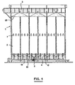
- FIGs. 1 and 2 there is shown in Figs. 1 and 2 an embodiment of a slow delayed cooling installation of the grain continuously.
- This installation comprises a silo generally designated by the reference 1, having a modular construction and providing chambers or columns 2 for cooling the grain.
- This silo is combined at its upper part with a grain feed device, indicated diagrammatically at 3 in FIGS. 1 and 2, capable of bringing grain to the silo from a grain dryer for example.
- a grain feed device indicated diagrammatically at 3 in FIGS. 1 and 2
- Cold air supply and distribution ducts indicated in 4 are provided towards the base of the silo, which will be described in more detail below and which ensure uniform air distribution throughout the base of the silo. These ducts 4 are supplied from fans 5.
- a system of ducts 7 forming an air collector which intercepts and evacuates towards the outside at 6 (Fig. 2) the drying and cooling air having penetrated into the silo by sheaths 4.
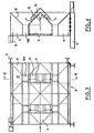
- FIGS. 3 and 4 There is shown in more detail in FIGS. 3 and 4 the lower part of the silo, with the air intake means.
- FIGs. 3 and 4 show a module generally designated by 8, with its support posts 9 and four cones directed downward for the outlet of the grain, the outlet orifices being indicated at 10a.
- the central part of the module is formed by the air inlet sheath 4, which constitutes a beam supporting the weight of the grain which is in the silo.
- Side parts 11 also constituting support beams complete the modular structure of the base of this silo.
- the upper part of the central sheath 4 has the shape of a roof, and there are provided towards the top of this part air outlet orifices, 12.
- This part provided with orifices 12 is covered with a cap 13 supported at a certain distance from the sheath 4 so that, as indicated by arrows in particular in FIG. 4, the air passing through this sheath 4 and exiting through the orifices 12 is deflected by the cap 13 to go up inside the grain substantially at the right of the flow orifices 10a of the discharge cones of the module.
- the sheath 4 ensuring the routing of air in a module communicates with the sheath 4 of the next module after the assembly of the modules, by rectangular orifices formed in the end flanks of the base, visible at 14 in FIG. . 2. This communication appears in FIG. 1.
- this structure supports the grain, avoiding a conventional beam with I and H profiles. It also allows simultaneous extraction by multi-cones in the entire horizontal cross section of the silo, a manner ensuring a descent of the grain in horizontal layers, which subjects all the fractions of the grain to a uniform slow cooling. Finally, by the ducts and caps described, it constitutes a ventilation and air injection network in the grain, with a direct distribution from one module to another.
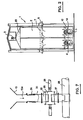
- each orifice 10a of an extraction cone 10 is extended downwards by a tube 15 to which another tube 16 is connected with the interposition of a flexible and watertight seal 17 which allows the deformations while preventing leaks d 'air.
- This tube 16 is in turn connected by a versatile connector 18 to a first sheath 19 in which is mounted a conveyor screw rotating at low speed.
- the speed of rotation of this screw is regulated by a variable speed drive which can, for example, be of the mechanical or electronic type, which makes possible a precise metering of the extraction of the grain.
- a variable speed drive which can, for example, be of the mechanical or electronic type, which makes possible a precise metering of the extraction of the grain.
- This arrangement of the extraction and evacuation system makes it possible to obtain a low overall height and it can be supported by bases as indicated at 22 in FIG. 5. This low height results in an appreciable gain in the cost of the posts and bracing irons are avoided because of the embedding of the side doors over the entire height of the bases.
- a two-screw extraction system of this type constitutes a substantially sealed extractor, which maintains the seal during extraction.
- Figs. 1 and 2 the grain embankment coming from a dryer and brought in by the feed device 3 is indicated at 23.
- the silo is filled with grain over its entire height. It is easily understood that there is produced by the cones 10 and tubes 15, 16, at the base of the silo, a sample of a certain amount of grain, depending on the speed of the screws. The mass of the grain then undergoes a gradual downward movement in the silo in horizontal layers. The screw speed can be adjusted according to the required residence time of the grain in the silo.
- the fans 5 send the entire base of the silo, via the ducts 4, cold air ensuring the cooling and the end of the drying of the grain.
- This air which enters the base of the silo rises inside the grain mass and is intercepted and evacuated to the outside by the duct system 7 located at an intermediate level.
- the grain in the upper part of the silo, the grain is not subjected to the effect of drying air. It therefore undergoes during its entire downward progression in the upper part of the silo a drying effect of internal humidity, similar to that obtained during its rest in a cell.
- a drying effect of internal humidity similar to that obtained during its rest in a cell.
- a tube 30 is connected to the base of the orifice 10a of the cone 10, this tube being here in two parts with the interposition of a flexible seal 24.
- This tube 23 is extended downwards by a nozzle 25 connecting to a lock body 26.
- An outlet nozzle 27 starting from this lock body 26 joins the sheath 28 of a collecting screw.
- a rotary lock of known type is mounted in the lock body 26. It is rotated by a shaft 29 whose speed is adjusted as a function of the output flow of the grain and consequently of the residence time of the grain in the silo .
- the means for removing the grain could be constituted by valves, pneumatic with register, which can be controlled all together or one after the other according to an opening rhythm determined here again as a function of the required residence time. for the grain inside the silo.
Landscapes
- Engineering & Computer Science (AREA)
- Mechanical Engineering (AREA)
- General Engineering & Computer Science (AREA)
- Life Sciences & Earth Sciences (AREA)
- Microbiology (AREA)
- Drying Of Solid Materials (AREA)
- Adjustment And Processing Of Grains (AREA)
- Water Treatment By Sorption (AREA)
Claims (4)
Priority Applications (1)
| Application Number | Priority Date | Filing Date | Title |
|---|---|---|---|
| AT81401565T ATE4840T1 (de) | 1980-10-09 | 1981-10-09 | Verfahren und vorrichtung zum traegen verzoegerten, ununterbrochenen kuehlen von getreide. |
Applications Claiming Priority (2)
| Application Number | Priority Date | Filing Date | Title |
|---|---|---|---|
| FR8021590A FR2491723A1 (fr) | 1980-10-09 | 1980-10-09 | Procede et installation pour le refroidissement lent differe du grain en continu |
| FR8021590 | 1980-10-09 |
Publications (3)
| Publication Number | Publication Date |
|---|---|
| EP0051008A1 EP0051008A1 (de) | 1982-05-05 |
| EP0051008B1 EP0051008B1 (de) | 1983-09-28 |
| EP0051008B2 true EP0051008B2 (de) | 1988-03-30 |
Family
ID=9246708
Family Applications (1)
| Application Number | Title | Priority Date | Filing Date |
|---|---|---|---|
| EP81401565A Expired EP0051008B2 (de) | 1980-10-09 | 1981-10-09 | Verfahren zum trägen verzögerten, ununterbrochenen Kühlen vonGetreide |
Country Status (7)
| Country | Link |
|---|---|
| US (1) | US4446630A (de) |
| EP (1) | EP0051008B2 (de) |
| AT (1) | ATE4840T1 (de) |
| BR (1) | BR8106511A (de) |
| CA (1) | CA1170419A (de) |
| DE (1) | DE3161043D1 (de) |
| FR (1) | FR2491723A1 (de) |
Families Citing this family (10)
| Publication number | Priority date | Publication date | Assignee | Title |
|---|---|---|---|---|
| FR2605851B1 (fr) * | 1986-11-05 | 1989-01-06 | Secemia | Procede et installation de traitement du grain sortant d'un sechoir, par refroidissement lent et extraction complementaire d'humidite |
| DE3639966A1 (de) * | 1986-11-22 | 1988-06-01 | Bergwerksverband Gmbh | Wirbelschichtreaktor aus edelstahlgussgehaeuse |
| FR2705442B1 (fr) * | 1993-05-13 | 1995-07-21 | Calmon Olivier | Dispositif de séchage en continu pour produits divisés en vrac. |
| US6202319B1 (en) * | 2000-01-13 | 2001-03-20 | Douglas Bening | Grain dryer heat exchanger |
| US7568297B2 (en) * | 2006-04-10 | 2009-08-04 | Woodhaven Capital Corp. | Grain drying aeration system |
| CN103628724B (zh) * | 2013-12-04 | 2016-06-22 | 河南工业大学 | 一种旋转抛物面形的地下粮仓 |
| US9950872B2 (en) | 2015-11-30 | 2018-04-24 | Superior Manufacturing LLC | Bin sweep auger unplugging system |
| CN111377155A (zh) * | 2020-04-03 | 2020-07-07 | 罗连巧 | 一种农业用谷物储存装置 |
| US11644237B2 (en) | 2020-09-18 | 2023-05-09 | LAW Iberica S.A. | Apparatus to process grain received from a dryer |
| US11304424B2 (en) | 2020-09-18 | 2022-04-19 | LAW Iberica S.A. | Method and apparatus to process grain process grain received from a dryer |
Family Cites Families (13)
| Publication number | Priority date | Publication date | Assignee | Title |
|---|---|---|---|---|
| US921395A (en) * | 1908-01-28 | 1909-05-11 | Hager Mfg Company | Grain-cooler. |
| GB256500A (en) * | 1925-09-11 | 1926-08-12 | Albin Klingler | Improvements in air distributing systems for drying kilns and the like |
| US1932830A (en) * | 1927-09-03 | 1933-10-31 | Koppers Co Inc | Apparatus for heating coal or the like |
| FR821091A (fr) * | 1937-01-30 | 1937-11-26 | Thomas Robinson & Son Ltd | Perfectionnements aux machines de séchage et de conditionnement pour céréales |
| FR912848A (fr) * | 1944-03-21 | 1946-08-21 | Gebru Der Bu Hler | Sécheur à cuve |
| GB647490A (en) * | 1945-07-19 | 1950-12-13 | Erie Mining Co | Heat-treating solids |
| US2560141A (en) * | 1948-06-21 | 1951-07-10 | James F Tipps | Means for cooling and drying grain and seed |
| US3302297A (en) * | 1964-09-09 | 1967-02-07 | Douglas L Graham | Drying apparatus and method |
| US3710449A (en) * | 1971-01-06 | 1973-01-16 | Gear Co M W | Grain dryer with improved grain deflector |
| US3721017A (en) * | 1971-05-10 | 1973-03-20 | L Niems | Apparatus for cooling particles |
| US3701203A (en) * | 1971-11-22 | 1972-10-31 | Andersons The | Particulate material drying apparatus |
| US4020561A (en) * | 1975-12-17 | 1977-05-03 | Mathews B C | Method and apparatus for drying grain |
| DE2744449C2 (de) * | 1976-10-05 | 1985-05-23 | Westlake Agricultural Engineering Inc., St. Marys, Ontario | Vorrichtung zur Steuerung der Strömung von körnigem Gut durch einen Trocknungsturm |
-
1980
- 1980-10-09 FR FR8021590A patent/FR2491723A1/fr active Granted
-
1981
- 1981-10-07 CA CA000387484A patent/CA1170419A/en not_active Expired
- 1981-10-08 BR BR8106511A patent/BR8106511A/pt unknown
- 1981-10-09 EP EP81401565A patent/EP0051008B2/de not_active Expired
- 1981-10-09 DE DE8181401565T patent/DE3161043D1/de not_active Expired
- 1981-10-09 US US06/310,067 patent/US4446630A/en not_active Expired - Fee Related
- 1981-10-09 AT AT81401565T patent/ATE4840T1/de not_active IP Right Cessation
Also Published As
| Publication number | Publication date |
|---|---|
| EP0051008B1 (de) | 1983-09-28 |
| EP0051008A1 (de) | 1982-05-05 |
| FR2491723B1 (de) | 1984-11-09 |
| CA1170419A (en) | 1984-07-10 |
| US4446630A (en) | 1984-05-08 |
| FR2491723A1 (fr) | 1982-04-16 |
| BR8106511A (pt) | 1982-06-29 |
| DE3161043D1 (en) | 1983-11-03 |
| ATE4840T1 (de) | 1983-10-15 |
Similar Documents
| Publication | Publication Date | Title |
|---|---|---|
| EP0051008B2 (de) | Verfahren zum trägen verzögerten, ununterbrochenen Kühlen vonGetreide | |
| EP0077715B1 (de) | Modultrockner zum Trocknen von Getreide | |
| FR2574810A1 (fr) | Reacteur a soles multiples et procede de traitement thermique de matieres carbonees | |
| EP0020260A1 (de) | Verfahren und Vorrichtung zum Trocknen verglasbarer verdichteter Mischungen | |
| CA1333520C (fr) | Mecanisme de chargement-dechargement d'une enceinte fermee utilisable comme cuve d'extraction d'une unite d'extraction en continu de vegetaux et procede d'extraction en comportantapplication | |
| FR2569471A1 (fr) | Sechoir a cereales | |
| EP0066661A1 (de) | Vorrichtung zum Trocknen von Bahnen durch Heissluft bei gleichzeitiger Unterstützung der Bahn, vorzugsweise von Papierbahnen aus Druckmaschinen | |
| FR2695988A1 (fr) | Procédé et dispositif de séchage de produits divisés, en vrac. | |
| FR2630621A1 (fr) | Sechoir a grain | |
| FR2563327A1 (fr) | Installation de sechage de produits par echange de chaleur avec un fluide de sechage | |
| EP0043324B1 (de) | Maschine zum Enthülsen, Rösten und Reinigen von Sesamsamen | |
| CN219698927U (zh) | 一种蔬菜脱水机 | |
| FR2476820A1 (fr) | Sechoir a cereales perfectionne | |
| CN2488024Y (zh) | 穿流干燥机 | |
| FR2488985A1 (fr) | Procede et appareil pour le refroidissement de granules | |
| FR2484203A1 (fr) | Perfectionnements aux sechoirs de matiere vegetale, notamment pour cereales | |
| FR2593900A1 (fr) | Procede et dispositif permettant de recuperer la chaleur sur des installations rejetant de l'air chaud charge de vapeur et d'accroitre la productivite de ces installations | |
| FR2564575A1 (fr) | Procede et dispositif de traitement thermique par reduction de la pression d'air regnant dans une chambre | |
| CN120052559A (zh) | 一种蔬菜风选干燥系统及方法 | |
| FR2564576A1 (fr) | Sechoir pour cereales, a systeme de rechauffage d'air perfectionne et systeme de rechauffage pour un tel sechoir | |
| EP0006799B1 (de) | Verfahren und Vorrichtung zur Erhöhung der Entwicklungsgeschwindigkeit in Diazokopiegeräten | |
| FR2556459A1 (fr) | Sechoir a cereales a entrees d'air reglables | |
| CH627545A5 (fr) | Procede et installation pour le sechage, a evaporation reglee de produits pulverulents moules. | |
| FR2539496A1 (fr) | Installation pour le traitement, notamment thermique, de produits ou matieres pulverulents, en grains, ou en morceaux de faible granulometrie | |
| EP0250297A2 (de) | Getreidetrockner |
Legal Events
| Date | Code | Title | Description |
|---|---|---|---|
| PUAI | Public reference made under article 153(3) epc to a published international application that has entered the european phase |
Free format text: ORIGINAL CODE: 0009012 |
|
| AK | Designated contracting states |
Designated state(s): AT DE GB IT SE |
|
| 17P | Request for examination filed |
Effective date: 19820809 |
|
| ITF | It: translation for a ep patent filed | ||
| GRAA | (expected) grant |
Free format text: ORIGINAL CODE: 0009210 |
|
| AK | Designated contracting states |
Designated state(s): AT DE GB IT SE |
|
| REF | Corresponds to: |
Ref document number: 4840 Country of ref document: AT Date of ref document: 19831015 Kind code of ref document: T |
|
| REF | Corresponds to: |
Ref document number: 3161043 Country of ref document: DE Date of ref document: 19831103 |
|
| PLBI | Opposition filed |
Free format text: ORIGINAL CODE: 0009260 |
|
| 26 | Opposition filed |
Opponent name: STE EUROGRAIN Effective date: 19840509 |
|
| PGFP | Annual fee paid to national office [announced via postgrant information from national office to epo] |
Ref country code: SE Payment date: 19840930 Year of fee payment: 4 |
|
| PGFP | Annual fee paid to national office [announced via postgrant information from national office to epo] |
Ref country code: AT Payment date: 19841031 Year of fee payment: 4 |
|
| PGFP | Annual fee paid to national office [announced via postgrant information from national office to epo] |
Ref country code: DE Payment date: 19841214 Year of fee payment: 4 |
|
| PG25 | Lapsed in a contracting state [announced via postgrant information from national office to epo] |
Ref country code: AT Effective date: 19851009 |
|
| PG25 | Lapsed in a contracting state [announced via postgrant information from national office to epo] |
Ref country code: SE Effective date: 19851010 |
|
| PG25 | Lapsed in a contracting state [announced via postgrant information from national office to epo] |
Ref country code: DE Effective date: 19860701 |
|
| PUAH | Patent maintained in amended form |
Free format text: ORIGINAL CODE: 0009272 |
|
| STAA | Information on the status of an ep patent application or granted ep patent |
Free format text: STATUS: PATENT MAINTAINED AS AMENDED |
|
| 27A | Patent maintained in amended form |
Effective date: 19880330 |
|
| AK | Designated contracting states |
Kind code of ref document: B2 Designated state(s): AT DE GB IT SE |
|
| ITF | It: translation for a ep patent filed | ||
| PGFP | Annual fee paid to national office [announced via postgrant information from national office to epo] |
Ref country code: GB Payment date: 19911004 Year of fee payment: 11 |
|
| ITTA | It: last paid annual fee | ||
| PG25 | Lapsed in a contracting state [announced via postgrant information from national office to epo] |
Ref country code: GB Effective date: 19921009 |
|
| GBPC | Gb: european patent ceased through non-payment of renewal fee |
Effective date: 19921009 |
|
| EUG | Se: european patent has lapsed |
Ref document number: 81401565.7 Effective date: 19860805 |