EP0051008B2 - Process for the slowly deferred continuous cooling of grain - Google Patents
Process for the slowly deferred continuous cooling of grain Download PDFInfo
- Publication number
- EP0051008B2 EP0051008B2 EP81401565A EP81401565A EP0051008B2 EP 0051008 B2 EP0051008 B2 EP 0051008B2 EP 81401565 A EP81401565 A EP 81401565A EP 81401565 A EP81401565 A EP 81401565A EP 0051008 B2 EP0051008 B2 EP 0051008B2
- Authority
- EP
- European Patent Office
- Prior art keywords
- grain
- column
- air
- silo
- drying
- Prior art date
- Legal status (The legal status is an assumption and is not a legal conclusion. Google has not performed a legal analysis and makes no representation as to the accuracy of the status listed.)
- Expired
Links
Images

Classifications
-
- F—MECHANICAL ENGINEERING; LIGHTING; HEATING; WEAPONS; BLASTING
- F26—DRYING
- F26B—DRYING SOLID MATERIALS OR OBJECTS BY REMOVING LIQUID THEREFROM
- F26B25/00—Details of general application not covered by group F26B21/00 or F26B23/00
-
- F—MECHANICAL ENGINEERING; LIGHTING; HEATING; WEAPONS; BLASTING
- F26—DRYING
- F26B—DRYING SOLID MATERIALS OR OBJECTS BY REMOVING LIQUID THEREFROM
- F26B17/00—Machines or apparatus for drying materials in loose, plastic, or fluidised form, e.g. granules, staple fibres, with progressive movement
- F26B17/12—Machines or apparatus for drying materials in loose, plastic, or fluidised form, e.g. granules, staple fibres, with progressive movement with movement performed solely by gravity, i.e. the material moving through a substantially vertical drying enclosure, e.g. shaft
- F26B17/14—Machines or apparatus for drying materials in loose, plastic, or fluidised form, e.g. granules, staple fibres, with progressive movement with movement performed solely by gravity, i.e. the material moving through a substantially vertical drying enclosure, e.g. shaft the materials moving through a counter-current of gas
-
- F—MECHANICAL ENGINEERING; LIGHTING; HEATING; WEAPONS; BLASTING
- F26—DRYING
- F26B—DRYING SOLID MATERIALS OR OBJECTS BY REMOVING LIQUID THEREFROM
- F26B3/00—Drying solid materials or objects by processes involving the application of heat
- F26B3/02—Drying solid materials or objects by processes involving the application of heat by convection, i.e. heat being conveyed from a heat source to the materials or objects to be dried by a gas or vapour, e.g. air
- F26B3/14—Drying solid materials or objects by processes involving the application of heat by convection, i.e. heat being conveyed from a heat source to the materials or objects to be dried by a gas or vapour, e.g. air the materials or objects to be dried being moved by gravity
- F26B3/16—Drying solid materials or objects by processes involving the application of heat by convection, i.e. heat being conveyed from a heat source to the materials or objects to be dried by a gas or vapour, e.g. air the materials or objects to be dried being moved by gravity in a counter-flow of the gas or vapour
Abstract
Description
La présente invention se rapporte à un procédé pour le refroidissement lent différé du grain en continu.The present invention relates to a method for the delayed slow cooling of the grain continuously.
Il est usuel de procéder à un séchage du grain récolté afin d'en éliminer l'humidité avant son entreposage. Cette opération est réalisée, actuellement, de façon courante dans des séchoirs trà- vaillant en continu, le grain étant introduit dans la partie supérieure du séchoir et étant prélevé à sa partie inférieure, des moyens étant prévus pour admettre dans le séchoir d'abord de l'air chaud, dans une ou plusieurs sections supérieures, puis de l'air froid, dans sa partie inférieure, afin de refroidir le grain avant son extraction du séchoir. Un tel procédé est décrit par exemple dans le document FR-A 2 367 259.It is customary to dry the harvested grain in order to remove moisture from it before storage. This operation is currently carried out, in a current manner in continuous working driers, the grain being introduced into the upper part of the drier and being taken from its lower part, means being provided for admitting into the drier first hot air, in one or more upper sections, then cold air, in its lower part, in order to cool the grain before its extraction from the dryer. Such a method is described for example in document FR-A 2 367 259.
Il est également connu de prévoir, dans un séchoir der ce type général, au moins une section dans laquelle il ne se produit aucune circulation d'air (Brevet FR-A 821 091, Brevet US-A 3 701203) de façon telle que la chaleur transmise au grain dans la zone de séchage (ou dans une zone de préséchage) puisse imprégner ce dernier en permettant une élévation de température de l'ensemble du grain.It is also known to provide, in a dryer of this general type, at least one section in which there is no air circulation (Patent FR-A 821,091, Patent US-A 3,701,203) so that the heat transmitted to the grain in the drying zone (or in a pre-drying zone) can permeate the latter by allowing a rise in temperature of the whole grain.
Il se produit alors dans le grain, pendant cette période, une migration de l'humidité intérieure vers la surface, ce qui favorise le séchage.During this period, there is a migration of interior moisture to the surface in the grain, which promotes drying.
Mais compte tenu du temps pendant lequel le grain demeure dans un séchoir entre son orifice d'entrée supérieure et sa base, la durée de séjour du grain dans ces zones de relaxation ou de ressuyage est nécessairement très limitée et elle est en fait trop courte pour permettre une migration suffisante de l'humidité du grain vers la surface pour rendre possible une terminaison du séchage au degré requis sous le seul effet de l'air de refroidissement.But taking into account the time during which the grain remains in a dryer between its upper inlet orifice and its base, the duration of the grain's stay in these relaxation or drying areas is necessarily very limited and it is in fact too short for allow sufficient migration of moisture from the grain to the surface to allow termination of drying to the required degree under the sole effect of cooling air.
Il est connu par ailleurs de sortir d'un séchoir du grain non totalement sec et encore chaud. Dans un tel cas, pour compléter le séchage, on utilise les calories contenues dans le grain à la sortie du séchoir, en assurant son repos dans une cellule. Il se produit, au cours de ce repos, un ressuyage de l'humité interne du grain, qui subit une migration vers l'extérieur ou vers la périphérie. Le phénomène qui se produit peut être comparé à celui intervenant dans la zone de relaxation d'un séchoir comme indiqué précédemment. Mais il est alors de durée nettement plus longue, ce qui permet une migration plus complète de l'humidité vers l'extérieur du grain, et en conséquence une extraction plus facile de cette humidité. Après cette migration, il suffit de procéder à une ventilation du grain avec un faible débit de renouvellement d'air pour compléter le séchage et le refroidissement, tel que décrit par exemple dans le US-A 2 560141:It is also known to come out of a grain dryer that is not completely dry and still hot. In such a case, to complete the drying, the calories contained in the grain at the outlet of the dryer are used, ensuring its rest in a cell. During this rest, a drying of the internal moisture of the grain takes place, which undergoes a migration towards the outside or towards the periphery. The phenomenon that occurs can be compared to that occurring in the relaxation zone of a dryer as previously indicated. But it is then significantly longer in duration, which allows a more complete migration of moisture towards the outside of the grain, and consequently an easier extraction of this moisture. After this migration, it suffices to ventilate the grain with a low air renewal rate to complete the drying and cooling, as described for example in US-A 2,560,141:
«Dans le document imprimé, référence ASAE Paper No. 77-3019 résultant d'une communication publique faite lors de la réunion annuelle de l'American Society of Agricultural Engineers, qui s'est tenue les 26 à 29 juin 1977 en Caroline du Nord (E.U.A.) il est décrit une installation de séchage comportant un séchoir concourant et une colonne de refroidissement dans laquelle le grain descend progressivement dans des conditions non ventilé puis, ensuite, selon un parcours ventilé jusqu'au bas de la colonne.»"In the printed document, reference ASAE Paper No. 77-3019 resulting from a public communication made at the annual meeting of the American Society of Agricultural Engineers, which was held on June 26-29, 1977 in North Carolina (EUA) there is described a drying installation comprising a concurrent dryer and a cooling column in which the grain descends progressively under non-ventilated conditions and then, according to a ventilated path to the bottom of the column. ”
Il résulte de ce procédé connu, dénommé procédé de refroidissement lent différé, outre un séchage plus homogène et plus efficace, comme indiqué précédemment, un gain de débit pour les séchoirs existants, une réduction de consommation d'énergie et une amélioration de la qualité du grain.It results from this known process, called the delayed slow cooling process, in addition to a more homogeneous and more efficient drying, as indicated above, a gain in throughput for existing dryers, a reduction in energy consumption and an improvement in the quality of the grain.
Tel qu'il est appliqué à l'heure actuelle, ce procédé présente toutefois un certain nombre d'in- convenients. En effet, il nécessite l'emploi de plusieurs silos équipés d'un système de refroidissement lent différé pour suivre le rythme fonctionnel d'un séchoir continu. En outre, le contrôle de l'opération doit être rigoureux pour respecter les phases nécessaires, ce qui exige la formation d'un personnel spécialisé qui doit également apporter une attention particulière au travail.As it is applied at present, however, this method has a number of drawbacks. Indeed, it requires the use of several silos equipped with a delayed slow cooling system to follow the functional rhythm of a continuous dryer. In addition, the control of the operation must be rigorous to respect the necessary phases, which requires the training of specialized personnel who must also pay particular attention to the work.
Le but de l'invention est de remédier aux inconvénients du procédé connu.The object of the invention is to remedy the drawbacks of the known method.
L'invention est matérialisée, à cet effet, dans un procédé de refroidissement lent différé du grain encore chaud et encore chargé d'humidité excédentaire prélevé à un séchoir, consistant, de façon continue, à assurer la descente progressive de ce grain à l'intérieur d'au moins une colonne, d'abord dans des conditions non ventilées, puis après un temps de descente correspondant au temps nécessaire au ressuyage de l'humidité interne du grain, à assurer la ventilation de ce grain pour compléter de séchage et le refroidissement tandis que ledit grain continue sa progression vers le bas à l'intérieur de la colonne, et à prélever le grain séché et refroidi à la colonne.The invention is materialized, for this purpose, in a slow delayed cooling process of the grain still hot and still charged with excess moisture taken from a dryer, consisting, continuously, in ensuring the gradual descent of this grain to the interior of at least one column, first in non-ventilated conditions, then after a descent time corresponding to the time necessary to dry the internal moisture of the grain, to ensure the ventilation of this grain to complete drying and cooling while said grain continues its downward progression inside the column, and taking the dried and cooled grain from the column.
Ainsi, le procédé général connu de refroidissement lent différé est mis en oeuvre d'une manière continue au cours de la progression du grain dans une même colonne, en évitant les inconvénients résultant de la capacité de stockage requise suivant la technique antérieure. A l'intérieur de la colonne, le grain est soumis à une séquence de traitement bien précise, qui différe de celle d'un séchoir en ce sens qu'aucun échauffement du grain ne se produit pour le séchage et que ce grain est soumis simplement à un temps de repos ou de ressuyage, puis à une ventilation de refroidissement.Thus, the general known method of delayed slow cooling is implemented continuously during the progression of the grain in the same column, avoiding the drawbacks resulting from the storage capacity required according to the prior art. Inside the column, the grain is subjected to a very precise treatment sequence, which differs from that of a dryer in that no heating of the grain occurs for drying and that this grain is subjected simply to a time of rest or drying, then to a cooling ventilation.
Ce procédé allie les avantages résultant du prélèvement à un séchoir d'un grain non encore séché au degré requis et encore chaud, avec le gain de débit et la réduction de consommation d'énergie qui y sont liés, et ceux résultant d'un ressuyage plus complet et plus long du grain, avec les avantages d'un traitement en continu dans un appareillage d'encrombrement nettement réduit par rapport aux installations existantes.This process combines the advantages resulting from the removal from a drier of a grain which is not yet dried to the required degree and still hot, with the gain in throughput and the reduction in energy consumption associated therewith, and those resulting from drying. more complete and longer grain, with the advantages of continuous treatment in a device with a significantly reduced size compared to existing installations.
Suivant un mode de mise en oeuvre préférentiel, on assure la ventilation du grain au cours de sa progression dans la colonne par passage d'air à contre-courant par rapport au sens de progression du grain. On peut ainsi, suivant l'invention, admettre de l'air au voisinage du point de sortie du grain par rapport à la colonne, c'est-à-dire à l'endroit où le grain est déjà suffisamment refroidi, ce qui évite le choc thermique du grain, en ré- suidant les fêlures.According to a preferred mode of implementation, the grain is ensured during its progression in the column by the passage of air against the current with respect to the direction of progress. grain. It is thus possible, according to the invention, to admit air in the vicinity of the point of exit of the grain relative to the column, that is to say at the place where the grain is already sufficiently cooled, which avoids the thermal shock of the grain, by preventing cracks.
Suivant une autre particularité de ce procédé, on effectue la ventilation du grain en pression, en assurant l'admission d'air froid au voisinage du point de sortie du grain par rapport à la colonne et l'évacuation de l'air à un niveau intermédiaire de cette colonne, choisi en fonction du temps de ressuyage requis. On peut alors récupérer l'énergie contenue dans l'air évacué de la colonne du fait du niveau enthalpique constant de cet air, qui est saturé et chaud et qui se trouve pratiquement à la même température que le grain après ressuyage. Cette récupération d'énergie peut se faire de toute manière désirée, par exemple au moyen d'un échangeur de chaleur, avec condensation de l'humidité contenue dans l'air.According to another particular feature of this process, the pressure of the grain is ventilated, ensuring the admission of cold air in the vicinity of the point of exit of the grain relative to the column and the evacuation of the air at a level intermediate of this column, chosen according to the drying time required. We can then recover the energy contained in the air evacuated from the column due to the constant enthalpy level of this air, which is saturated and hot and which is practically at the same temperature as the grain after drying. This energy recovery can be done in any desired way, for example by means of a heat exchanger, with condensation of the humidity contained in the air.
Un autre avantage encore du procédé suivant l'invention réside dans le fait que l'homogénéité du grain séché est améliorée par suite de sa progression régulière et continue dans la colonne. II s'établit alors entre les grains des modifications de contact par rapport aux grains voisins, ce qui favorise les échanges avec l'air et accroît en conséquence l'efficacité de la ventilation.Yet another advantage of the process according to the invention lies in the fact that the homogeneity of the dried grain is improved as a result of its regular and continuous progression in the column. It then establishes between the grains of contact changes compared to neighboring grains, which promotes exchanges with air and consequently increases the efficiency of ventilation.
La description qui va suivre faite en regard des dessins annexés, donnés à titre non limitatif, permettra de mieux comprendre l'invention.
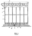
- La Fig. 1 est une vue schématique en élévation d'une installation de refroidissement lent différé du grain en continu.
- La Fig. 2 est une vue prise dans un plan perpendiculaire à celui de la Fig. 1.
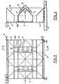
- La Fig. est une vue en plan de la partie inférieure d'un module.
- La Fig. 4 est une vue en coupe par la ligne IV-IV en Fig. 3.
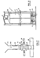
- La Fig.5 est une vue partielle schématique montrant la base d'un module de l'installation.
- La Fig. 6 est une vue analogue à la Fig. 5, mais en regardant dans une direction décalée de 90°.
- La Fig. 7 est une vue analogue à la Fig. mais correspondant à une variante de réalisation.
- Fig. 1 is a schematic elevation view of a slow delayed cooling installation of the grain continuously.
- Fig. 2 is a view taken in a plane perpendicular to that of FIG. 1.
- Fig. is a plan view of the lower part of a module.
- Fig. 4 is a sectional view through the line IV-IV in FIG. 3.
- Fig.5 is a partial schematic view showing the base of a module of the installation.
- Fig. 6 is a view similar to FIG. 5, but looking in a direction offset by 90 °.
- Fig. 7 is a view similar to FIG. but corresponding to an alternative embodiment.
On a représenté sur les Fig. 1 et 2 un mode de réalisation d'installation de refroidissement lent différé du grain en continu. Cette installation comprend un silo désigné d'une façon générale par la référence 1, présentant une construction modulaire et ménageant des enceintes ou colonnes 2 de refroidissement du grain.There is shown in Figs. 1 and 2 an embodiment of a slow delayed cooling installation of the grain continuously. This installation comprises a silo generally designated by the reference 1, having a modular construction and providing chambers or
Ce silo est combiné à sa partie supérieure avec un dispositif d'alimentation en grain, indiqué schématiquement en 3 sur les Fig. 1 et 2, capable d'amener du grain au silo depuis un séchoir à grain par exemple. On prévoit judicieusement des dispositifs de contrôle du niveau du grain dans le silo et un dispositif de régulation, ces dispositifs pouvant être de type en soi connu.This silo is combined at its upper part with a grain feed device, indicated diagrammatically at 3 in FIGS. 1 and 2, capable of bringing grain to the silo from a grain dryer for example. There are judiciously provided devices for controlling the level of the grain in the silo and a regulating device, these devices possibly being of a type known per se.
Il est prévu vers la base du silo des gaines d'alimentation en air froid et de distribution indiquées en 4, qui seront décrites plus en détail plus loin et qui assurent une répartition d'air uniforme dans toute la base du silo. Ces gaines 4 sont alimentées à partir de ventilateurs 5.Cold air supply and distribution ducts indicated in 4 are provided towards the base of the silo, which will be described in more detail below and which ensure uniform air distribution throughout the base of the silo. These
A un niveau intermédiaire du silo, il est prévu un système de gaines 7 formant un collecteur d'air qui intercepte et évacue vers l'extérieur en 6 (Fig.2) l'air de séchage et de refroidissement ayant pénétré dans le silo par les gaines 4.At an intermediate level of the silo, there is provided a system of
On a représenté de façon plus détaillée sur les Fig. 3 et 4 la partie inférieure du silo, avec les moyens d'admission de l'air.There is shown in more detail in FIGS. 3 and 4 the lower part of the silo, with the air intake means.
Ces Fig. 3 et 4 montrent un module désigné d'une façon générale par 8, avec ses poteaux de support 9 et quatre cônes dirigés vers le bas pour la sortie du grain, les orifices de sortie étant indiqués en 10a.These Figs. 3 and 4 show a module generally designated by 8, with its
La partie centrale du module est formée par la gaine 4 d'arrivée de l'air, qui constitue une poutre supportant le poids du grain qui se trouve dans le silo. Des parties latérales 11 constituant également des poutres de support complètent la structure modulaire de la base de ce silo.The central part of the module is formed by the
Comme indiqué sur les Fig. 3 et 4, la partie supérieure de la gaine centrale 4 a une forme de toit, et il est prévu vers le sommet de cette partie des orifices de sortie d'air, 12. Cette partie munie d'orifices 12 est recouverte d'un chapeau 13 soutenu à une certaine distance de la gaine 4 de telle sorte que, comme indiquée par des flèches en particulier sur la Fig. 4, l'air passant par cette gaine 4 et sortant par les orifices 12 soit dévié par le chapeau 13 pour remonter à l'intérieur du grain sensiblement au droit des orifices d'écoulement 10a des cônes d'évacuation du module.As shown in Figs. 3 and 4, the upper part of the
La gaine 4 assurant l'acheminement de l'air dans un module communique avec la gaine 4 du module suivant après l'assemblage des modules, par des orifices rectangulaires ménagés dans les flancs d'extrémité de la base, visibles en 14 sur la Fig. 2. Cette communication apparaît sur la Fig. 1.The
On voit que l'on obtient ainsi, pour la base du silo, une structure autoporteuse qui remplit trois fonctions différentes. En effet, cette structure supporte le grain, en évitant un poutrage classique avec des profilés en I et en H. Elle permet en outre une extraction simultanée par des mul- ti-cônes dans la totalité de la section droite horizontale du silo, d'une manière assurant une descente du grain en couches horizontales, ce qui soumet toutes les fractions du grain à un refroidissement lent uniforme. Enfin, elle constitue par les gaines et les chapeaux décrits un réseau de ventilation et d'injection d'air dans le grain, avec une répartition directe d'un module à l'autre.We see that we thus obtain, for the base of the silo, a self-supporting structure which fulfills three different functions. Indeed, this structure supports the grain, avoiding a conventional beam with I and H profiles. It also allows simultaneous extraction by multi-cones in the entire horizontal cross section of the silo, a manner ensuring a descent of the grain in horizontal layers, which subjects all the fractions of the grain to a uniform slow cooling. Finally, by the ducts and caps described, it constitutes a ventilation and air injection network in the grain, with a direct distribution from one module to another.
On a montré sur les Fig. 5 et 6 un mode de réalisation préférentiel de système d'extraction. Les éléments déjà visibles sur les Fig. 3 et 4 ont été désignés ici par les mêmes références. On voit que chaque orifice 10a d'un cône d'extraction 10 est prolongé vers le bas par un tube 15 auquel se raccorde un autre tube 16 avec interposition d'un joint souple et étanche 17 qui permet les déformations tout en évitant les fuites d'air. Ce tube 16 est reliée à son tour par un raccord polyvalent 18 à une première gaine 19 dans laquelle est montée une vis transporteuse tournant à faible vitesse. La vitesse de rotation de cette vis est réglée par un motovariateur qui peut être par exemple de type mécanique ou électronique, ce qui rend possible un dosage précis de l'extraction du grain. Il est prévu, au-dessous de cette première gaine 19, une autre gaine 20 réliée à la précédente par des raccords 21 et dans laquelle est montée une vis transporteuse collectrice à gros débit, assurant l'évacuation du grain par exemple vers un poste de stockage.We have shown in Figs. 5 and 6 a preferred embodiment of the extraction system. The elements already visible in Figs. 3 and 4 have been designated here by the same references. It can be seen that each
On voit en particulier à l'examen de la Fig. 6, sur laquelle des flèches indiquent le sens de transport du grain par les vis, que le grain de la gaine supérieure à faible débit tombe après un très court trajet dans la gaine inférieure à gros débit. Il va de soi d'ailleurs que les sens de transport dans le deux gaines pourraient être les mêmes au lieu d'être opposés.We see in particular on examining FIG. 6, in which arrows indicate the direction of grain transport by the screws, that the grain of the upper sheath at low flow rate falls after a very short journey in the lower sheath at high flow rate. It goes without saying, moreover, that the directions of transport in the two sheaths could be the same instead of being opposite.
Cet agencement du système d'extraction et d'évacuation permet d'obtenir une faible hauteur d'ensemble et il peut être soutenu par des embases comme indiqué en 22 sur la Fig. 5. Il résulte de cette faible hauteur un gain appréciable sur le coût des poteaux et on évite les fers de contreventement du fait de l'encastrement des por- teaux latéraux sur toute la hauteur des bases. En outre, un système d'extraction à deux vis de ce type constitue un extracteur sensiblement étanche, qui assure le maintient de l'étanchéité pendant l'extraction.This arrangement of the extraction and evacuation system makes it possible to obtain a low overall height and it can be supported by bases as indicated at 22 in FIG. 5. This low height results in an appreciable gain in the cost of the posts and bracing irons are avoided because of the embedding of the side doors over the entire height of the bases. In addition, a two-screw extraction system of this type constitutes a substantially sealed extractor, which maintains the seal during extraction.
On décrira maintenant le fonctionnement d'ensemble d'un silo de refroidissement lent différé en continu suivant l'invention.We will now describe the overall operation of a slow cooling silo continuously differed according to the invention.
Sur les Fig. 1 et 2, on a indiqué en 23 le talus de grain provenant d'un séchoir et amené par le dispositif d'alimentation 3. Le silo est rempli de grain sur toute sa hauteur. On conçoit aisément qu'il se produit par les cônes 10 et tubes 15, 16, à la base du silo, un prélèvement d'une certaine quantité de grain, en fonction de la vitesse des vis. La masse du grain subit alors dans le silo un déplacement progressif vers le bas par couches horizontales. La vitesse des vis peut être réglée en fonction du temps de séjour requis du grain dans le silo.In Figs. 1 and 2, the grain embankment coming from a dryer and brought in by the
Pendant le fonctionnement, les ventilateurs 5 envoient dans la totalité de la base du silo, par l'intermédiaire des gaines 4, de l'air froid assurant le refroidissement et le fin du séchage du grain. Cet air qui pénètre dans la base du silo s'éléve à l'intérieur de la masse du grain et il est intercepté et évacué vers l'extérieur par le système de gaines 7 situé à un niveau intermédiaire.During operation, the
Ainsi, dans la partie supérieure du silo, le grain n'est pas soumis à l'effet d'air de séchage. Il subit donc pendant toute sa progression vers le bas dans la partie supérieure du silo un effet de ressuyage de l'humidité interne, analogue à celui obtenu au cours de son repos dans une cellule. Quand le grain arrive, au cours de sa descente, au niveau intermédiaire du système de gaines 7 et le franchit, il commence à subir l'effet de l'air qui va compléter son séchage et son refroidissement.Thus, in the upper part of the silo, the grain is not subjected to the effect of drying air. It therefore undergoes during its entire downward progression in the upper part of the silo a drying effect of internal humidity, similar to that obtained during its rest in a cell. When the grain arrives, during its descent, at the intermediate level of the
Etant donné que l'air froid est introduit dans le silo par sa base, juste en amont des extracteurs, cet air froid vient en contact avec du grain en principe complètement refroidi, ce aqui évite tout choc thermique pour le grain. Au fur et à mesure de sa progression vers le haut à l'intérieur du grain, cet air se réchauffe en venant en contact avec du grain de plus chaud, et l'air quittant le silo se trouve sensiblement à la température du grain à la fin du stade de ressuyage. L'air s'échappant vers l'extérieur peut alors être traité pour la récupération des calories qu'il contient, avec condensation de l'humidité.Since cold air is introduced into the silo through its base, just upstream of the extractors, this cold air comes into contact with grain which is in principle completely cooled, this aqui avoids any thermal shock for the grain. As it progresses upwards inside the grain, this air heats up when it comes into contact with hotter grain, and the air leaving the silo is at substantially the temperature of the grain at the end of the drying stage. The air escaping to the outside can then be treated to recover the calories it contains, with condensation of humidity.
On a montré sur la Fig. 7 une variante de réalisation de moyens d'extraction du grain à la base du silo. Dans ce cas, un tube 30 est relié à la base de l'orifice 10a du cône 10, ce tube étant ici en deux parties avec interposition d'un joint souple 24. Ce tube 23 est prolongé vers le bas par une buse 25 se raccordant à un corps d'écluse 26. Une buse de sortie 27 partant de ce corps d'écluse 26 rejoint la gaine 28 d'une vis collectrice.We have shown in FIG. 7 an alternative embodiment of grain extraction means at the base of the silo. In this case, a
Une écluse rotative de type connu est montée dans le corps d'écluse 26. Elle est entraînée en rotation par un arbre 29 dont la vitesse est réglée en fonction du débit de sortie du grain et en conséquence du temps de séjour du grain dans le silo.A rotary lock of known type is mounted in the
Le fonctionnement d'ensemble d'un silo ainsi équipé est le même que précédemment.The overall operation of a silo thus equipped is the same as before.
Des modifications peuvent être apportées aux modes de réalisation décrits, dans le domaine des équivalences techniques. Ainsi, comme indiqué précédemment, les moyens de prélèvement du grain pourraient être constitués par des vannes, pneumatiques à registre, pouvant être commandées toutes ensemble ou les unes après les autres selon un ryhtme d'ouverture déterminé ici encore en fonction du temps de séjour requis pour le grain à l'intéieur du silo.Modifications can be made to the embodiments described, in the field of technical equivalences. Thus, as indicated above, the means for removing the grain could be constituted by valves, pneumatic with register, which can be controlled all together or one after the other according to an opening rhythm determined here again as a function of the required residence time. for the grain inside the silo.
Claims (4)
Priority Applications (1)
| Application Number | Priority Date | Filing Date | Title |
|---|---|---|---|
| AT81401565T ATE4840T1 (en) | 1980-10-09 | 1981-10-09 | METHOD AND DEVICE FOR CONDUCTING DELAYED CONTINUOUS COOLING OF GRAIN. |
Applications Claiming Priority (2)
| Application Number | Priority Date | Filing Date | Title |
|---|---|---|---|
| FR8021590 | 1980-10-09 | ||
| FR8021590A FR2491723A1 (en) | 1980-10-09 | 1980-10-09 | PROCESS AND PLANT FOR CONTINUOUSLY SLOW DELAY COOLING OF GRAIN |
Publications (3)
| Publication Number | Publication Date |
|---|---|
| EP0051008A1 EP0051008A1 (en) | 1982-05-05 |
| EP0051008B1 EP0051008B1 (en) | 1983-09-28 |
| EP0051008B2 true EP0051008B2 (en) | 1988-03-30 |
Family
ID=9246708
Family Applications (1)
| Application Number | Title | Priority Date | Filing Date |
|---|---|---|---|
| EP81401565A Expired EP0051008B2 (en) | 1980-10-09 | 1981-10-09 | Process for the slowly deferred continuous cooling of grain |
Country Status (7)
| Country | Link |
|---|---|
| US (1) | US4446630A (en) |
| EP (1) | EP0051008B2 (en) |
| AT (1) | ATE4840T1 (en) |
| BR (1) | BR8106511A (en) |
| CA (1) | CA1170419A (en) |
| DE (1) | DE3161043D1 (en) |
| FR (1) | FR2491723A1 (en) |
Families Citing this family (10)
| Publication number | Priority date | Publication date | Assignee | Title |
|---|---|---|---|---|
| FR2605851B1 (en) * | 1986-11-05 | 1989-01-06 | Secemia | PROCESS AND PLANT FOR TREATING GRAIN FROM A DRYER, BY SLOW COOLING AND COMPLEMENTARY MOISTURE EXTRACTION |
| DE3639966A1 (en) * | 1986-11-22 | 1988-06-01 | Bergwerksverband Gmbh | Fluidized bed reactor made of cast stainless steel |
| FR2705442B1 (en) * | 1993-05-13 | 1995-07-21 | Calmon Olivier | Continuous drying device for products divided in bulk. |
| US6202319B1 (en) * | 2000-01-13 | 2001-03-20 | Douglas Bening | Grain dryer heat exchanger |
| US7568297B2 (en) * | 2006-04-10 | 2009-08-04 | Woodhaven Capital Corp. | Grain drying aeration system |
| CN103628724B (en) * | 2013-12-04 | 2016-06-22 | 河南工业大学 | A kind of underground granary of paraboloid of revolution shape |
| US9950872B2 (en) | 2015-11-30 | 2018-04-24 | Superior Manufacturing LLC | Bin sweep auger unplugging system |
| CN111377155A (en) * | 2020-04-03 | 2020-07-07 | 罗连巧 | Cereal storage device is used to agricultural |
| US11644237B2 (en) | 2020-09-18 | 2023-05-09 | LAW Iberica S.A. | Apparatus to process grain received from a dryer |
| US11304424B2 (en) | 2020-09-18 | 2022-04-19 | LAW Iberica S.A. | Method and apparatus to process grain process grain received from a dryer |
Family Cites Families (13)
| Publication number | Priority date | Publication date | Assignee | Title |
|---|---|---|---|---|
| US921395A (en) * | 1908-01-28 | 1909-05-11 | Hager Mfg Company | Grain-cooler. |
| GB256500A (en) * | 1925-09-11 | 1926-08-12 | Albin Klingler | Improvements in air distributing systems for drying kilns and the like |
| US1932830A (en) * | 1927-09-03 | 1933-10-31 | Koppers Co Inc | Apparatus for heating coal or the like |
| FR821091A (en) * | 1937-01-30 | 1937-11-26 | Thomas Robinson & Son Ltd | Improvements to drying and packaging machines for cereals |
| FR912848A (en) * | 1944-03-21 | 1946-08-21 | Gebru Der Bu Hler | Tank dryer |
| GB647490A (en) * | 1945-07-19 | 1950-12-13 | Erie Mining Co | Heat-treating solids |
| US2560141A (en) * | 1948-06-21 | 1951-07-10 | James F Tipps | Means for cooling and drying grain and seed |
| US3302297A (en) * | 1964-09-09 | 1967-02-07 | Douglas L Graham | Drying apparatus and method |
| US3710449A (en) * | 1971-01-06 | 1973-01-16 | Gear Co M W | Grain dryer with improved grain deflector |
| US3721017A (en) * | 1971-05-10 | 1973-03-20 | L Niems | Apparatus for cooling particles |
| US3701203A (en) * | 1971-11-22 | 1972-10-31 | Andersons The | Particulate material drying apparatus |
| US4020561A (en) * | 1975-12-17 | 1977-05-03 | Mathews B C | Method and apparatus for drying grain |
| DE2744449C2 (en) * | 1976-10-05 | 1985-05-23 | Westlake Agricultural Engineering Inc., St. Marys, Ontario | Device for controlling the flow of granular material through a drying tower |
-
1980
- 1980-10-09 FR FR8021590A patent/FR2491723A1/en active Granted
-
1981
- 1981-10-07 CA CA000387484A patent/CA1170419A/en not_active Expired
- 1981-10-08 BR BR8106511A patent/BR8106511A/en unknown
- 1981-10-09 US US06/310,067 patent/US4446630A/en not_active Expired - Fee Related
- 1981-10-09 DE DE8181401565T patent/DE3161043D1/en not_active Expired
- 1981-10-09 AT AT81401565T patent/ATE4840T1/en not_active IP Right Cessation
- 1981-10-09 EP EP81401565A patent/EP0051008B2/en not_active Expired
Also Published As
| Publication number | Publication date |
|---|---|
| DE3161043D1 (en) | 1983-11-03 |
| BR8106511A (en) | 1982-06-29 |
| EP0051008A1 (en) | 1982-05-05 |
| FR2491723A1 (en) | 1982-04-16 |
| ATE4840T1 (en) | 1983-10-15 |
| US4446630A (en) | 1984-05-08 |
| FR2491723B1 (en) | 1984-11-09 |
| CA1170419A (en) | 1984-07-10 |
| EP0051008B1 (en) | 1983-09-28 |
Similar Documents
| Publication | Publication Date | Title |
|---|---|---|
| EP0051008B2 (en) | Process for the slowly deferred continuous cooling of grain | |
| FR2461120A1 (en) | INSTALLATION FOR THE EXPLOITATION OF THE ENERGY OF ASCENTAL AIR STREAMS IN DRAFT FIREPLACES | |
| FR2574810A1 (en) | MULTIPLE SOIL REACTOR AND METHOD OF HEAT TREATING CARBONACEOUS MATERIALS | |
| EP0077715A1 (en) | Modulated dryer for drying grain | |
| EP0313441A1 (en) | Device for unloading-loading a closed vessel for use as an extraction tank for a continuously operating extraction unit for vegetable materials, and process using it | |
| FR2763324A1 (en) | Producing salt by evaporating sea water | |
| FR2544476A1 (en) | DRIER OF LIQUID OR PASTY PRODUCTS AND INSTALLATION COMPRISING SUCH A DRYER | |
| FR2563327A1 (en) | Installation for drying products by heat exchange with a drying fluid | |
| EP0043324B1 (en) | Machine for the husking, roasting and cleaning of sesame grains | |
| FR2630621A1 (en) | Grain dryer | |
| FR2636127A1 (en) | Method and installation for drying wood, of the discontinuous type, in the presence of steam | |
| CN219698927U (en) | Vegetable dehydrator | |
| FR2476820A1 (en) | Grain dryer with hot air circulation - has cooling stage including fan extractor for wet air | |
| FR2488985A1 (en) | METHOD AND APPARATUS FOR COOLING PELLETS | |
| FR2465975A1 (en) | CONTINUOUS DRYER FOR WET CEREALS | |
| FR2593900A1 (en) | METHOD AND DEVICE FOR RECOVERING HEAT ON INSTALLATIONS DISCHARGING HOT STEAM-LOADED AIR AND INCREASING THE PRODUCTIVITY OF THESE FACILITIES | |
| FR2480920A2 (en) | Grain dryer with heating and cooling chambers - has part of exhausted heated air recycled to lower heating chamber | |
| FR2564576A1 (en) | Cereal drier, having an improved air heating system and a heating system for such a drier | |
| EP0006799B1 (en) | Process and device to improve the developing speed in a diazocopy apparatus | |
| FR2556459A1 (en) | Cereal drier with adjustable air inlets | |
| CH627545A5 (en) | METHOD AND PLANT FOR DRYING, WITH CONTROLLED EVAPORATION OF MOLDED POWDER PRODUCTS. | |
| FR2539496A1 (en) | Installation for the treatment (processing), in particular the heat treatment (processing), of products or materials which are in the form of powders, granules or small lumps | |
| EP0250297A2 (en) | Grain dryer | |
| FR2564575A1 (en) | METHOD AND DEVICE FOR THERMAL TREATMENT BY REDUCING REGULATING AIR PRESSURE IN A CHAMBER | |
| BE503199A (en) |
Legal Events
| Date | Code | Title | Description |
|---|---|---|---|
| PUAI | Public reference made under article 153(3) epc to a published international application that has entered the european phase |
Free format text: ORIGINAL CODE: 0009012 |
|
| AK | Designated contracting states |
Designated state(s): AT DE GB IT SE |
|
| 17P | Request for examination filed |
Effective date: 19820809 |
|
| ITF | It: translation for a ep patent filed |
Owner name: SAIC BREVETTI S.R.L. |
|
| GRAA | (expected) grant |
Free format text: ORIGINAL CODE: 0009210 |
|
| AK | Designated contracting states |
Designated state(s): AT DE GB IT SE |
|
| REF | Corresponds to: |
Ref document number: 4840 Country of ref document: AT Date of ref document: 19831015 Kind code of ref document: T |
|
| REF | Corresponds to: |
Ref document number: 3161043 Country of ref document: DE Date of ref document: 19831103 |
|
| PLBI | Opposition filed |
Free format text: ORIGINAL CODE: 0009260 |
|
| 26 | Opposition filed |
Opponent name: STE EUROGRAIN Effective date: 19840509 |
|
| PGFP | Annual fee paid to national office [announced via postgrant information from national office to epo] |
Ref country code: SE Payment date: 19840930 Year of fee payment: 4 |
|
| PGFP | Annual fee paid to national office [announced via postgrant information from national office to epo] |
Ref country code: AT Payment date: 19841031 Year of fee payment: 4 |
|
| PGFP | Annual fee paid to national office [announced via postgrant information from national office to epo] |
Ref country code: DE Payment date: 19841214 Year of fee payment: 4 |
|
| PG25 | Lapsed in a contracting state [announced via postgrant information from national office to epo] |
Ref country code: AT Effective date: 19851009 |
|
| PG25 | Lapsed in a contracting state [announced via postgrant information from national office to epo] |
Ref country code: SE Effective date: 19851010 |
|
| PG25 | Lapsed in a contracting state [announced via postgrant information from national office to epo] |
Ref country code: DE Effective date: 19860701 |
|
| PUAH | Patent maintained in amended form |
Free format text: ORIGINAL CODE: 0009272 |
|
| STAA | Information on the status of an ep patent application or granted ep patent |
Free format text: STATUS: PATENT MAINTAINED AS AMENDED |
|
| 27A | Patent maintained in amended form |
Effective date: 19880330 |
|
| AK | Designated contracting states |
Kind code of ref document: B2 Designated state(s): AT DE GB IT SE |
|
| ITF | It: translation for a ep patent filed |
Owner name: SAIC BREVETTI S.R.L. |
|
| PGFP | Annual fee paid to national office [announced via postgrant information from national office to epo] |
Ref country code: GB Payment date: 19911004 Year of fee payment: 11 |
|
| ITTA | It: last paid annual fee | ||
| PG25 | Lapsed in a contracting state [announced via postgrant information from national office to epo] |
Ref country code: GB Effective date: 19921009 |
|
| GBPC | Gb: european patent ceased through non-payment of renewal fee |
Effective date: 19921009 |
|
| EUG | Se: european patent has lapsed |
Ref document number: 81401565.7 Effective date: 19860805 |