EP0050626B1 - Procede et dispositif d'obtention en continu de lingots de metaux non ferreux a empilage auto-bloquant a partir d'une ebauche issue d'une machine de coulee sur roue a gorge - Google Patents
Procede et dispositif d'obtention en continu de lingots de metaux non ferreux a empilage auto-bloquant a partir d'une ebauche issue d'une machine de coulee sur roue a gorge Download PDFInfo
- Publication number
- EP0050626B1 EP0050626B1 EP81900965A EP81900965A EP0050626B1 EP 0050626 B1 EP0050626 B1 EP 0050626B1 EP 81900965 A EP81900965 A EP 81900965A EP 81900965 A EP81900965 A EP 81900965A EP 0050626 B1 EP0050626 B1 EP 0050626B1
- Authority
- EP
- European Patent Office
- Prior art keywords
- blank
- jaws
- impressions
- self
- ingots
- Prior art date
- Legal status (The legal status is an assumption and is not a legal conclusion. Google has not performed a legal analysis and makes no representation as to the accuracy of the status listed.)
- Expired
Links
- 238000000034 method Methods 0.000 title claims abstract description 15
- 229910052751 metal Inorganic materials 0.000 title claims abstract description 7
- 239000002184 metal Substances 0.000 title claims abstract description 7
- CWYNVVGOOAEACU-UHFFFAOYSA-N Fe2+ Chemical compound [Fe+2] CWYNVVGOOAEACU-UHFFFAOYSA-N 0.000 title claims abstract description 4
- 238000005266 casting Methods 0.000 title description 7
- 238000010924 continuous production Methods 0.000 title description 2
- 238000009749 continuous casting Methods 0.000 claims abstract description 4
- 238000005520 cutting process Methods 0.000 claims abstract description 4
- 229910052782 aluminium Inorganic materials 0.000 claims abstract description 3
- XAGFODPZIPBFFR-UHFFFAOYSA-N aluminium Chemical compound [Al] XAGFODPZIPBFFR-UHFFFAOYSA-N 0.000 claims abstract description 3
- 239000004411 aluminium Substances 0.000 claims abstract 2
- 238000004519 manufacturing process Methods 0.000 claims 2
- 238000010008 shearing Methods 0.000 abstract description 4
- 238000009434 installation Methods 0.000 description 2
- 210000002445 nipple Anatomy 0.000 description 2
- 230000000903 blocking effect Effects 0.000 description 1
- 238000010276 construction Methods 0.000 description 1
- 239000010730 cutting oil Substances 0.000 description 1
- 238000006073 displacement reaction Methods 0.000 description 1
- 230000000694 effects Effects 0.000 description 1
- 230000001788 irregular Effects 0.000 description 1
- 238000005304 joining Methods 0.000 description 1
- 229910001338 liquidmetal Inorganic materials 0.000 description 1
- 239000011159 matrix material Substances 0.000 description 1
- 238000000465 moulding Methods 0.000 description 1
- 239000002994 raw material Substances 0.000 description 1
- 238000007711 solidification Methods 0.000 description 1
- 230000008023 solidification Effects 0.000 description 1
- 230000001360 synchronised effect Effects 0.000 description 1
Images
Classifications
-
- B—PERFORMING OPERATIONS; TRANSPORTING
- B22—CASTING; POWDER METALLURGY
- B22D—CASTING OF METALS; CASTING OF OTHER SUBSTANCES BY THE SAME PROCESSES OR DEVICES
- B22D5/00—Machines or plants for pig or like casting
- B22D5/005—Devices for stacking pigs; Pigforms to be stacked
Definitions
- the invention relates to a method and a device for continuously obtaining, from a non-ferrous metal blank from a continuous casting machine on a grooved wheel, ingots of constant section and having bosses at their ends. suitable for making self-blocking stacks.
- ingots having hollow and / or raised portions on one or more of their faces can be produced from molds of suitable shape, in order to prevent any relative movement of the ingots with respect to each other when they are assembled in the form of stacks and thus making their transport convenient.
- the process according to the invention consists, in a known manner, of casting a blank on a grooved wheel temporarily closed by a ribbon and periodically making this blank integral with a device responsible for sharing it in ingots, but it is characterized in that that the blank is first clamped progressively on two opposite longitudinal side faces using two jaws in order to form imprints in line with these jaws, these imprints each comprising an edge extending over the entire height of the blank, and to develop at least one boss on at least one of the two other lateral faces, the boss or bosses being in a transverse plane passing through the imprints, the blank then being sheared in line with the imprints.
- the method uses, as a raw material, a blank from a casting machine on a grooved wheel temporarily closed by a ribbon to form a mold with movable walls.
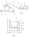
- the preform leaving the casting machine is first brought in a horizontal direction to be threaded between the cylinders of a straightener which gives it a suitable straightness, then it engages in the device responsible for sharing it in ingots.
- This device is fixed by a mobile carriage which includes means for making it integral with the blank.
- the blank drives the carriage with it, which allows the device to move synchronously with the blank and to exercise its sharing action on a determined section of the latter. .
- the blank is first of all clamped progressively on two opposite longitudinal side faces using two jaws connected to the carriage so as to form imprints in line with these jaws and to develop on at at least one of the other two faces, at least one boss.
- imprints which extend over the entire height of the blank are preferably symmetrical with respect to a vertical plane passing through the axis of the blank and they more or less follow the slope of the lateral faces.
- the depth of these imprints can vary depending on the nature of the product or the shape of the blank.
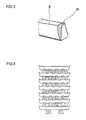
- the bosses which develop on the lower and / or upper face of the blank are located in a transverse plane passing through the imprints and appear on a section in line with the imprints as two nipples separated by a hollow; these nipples dominate the plane of these faces with a height which can be of the order of 1/10 of the height of the blank and join this face according to a convex curve.
- the blank is cut in a plane perpendicular or oblique to its axis, to the right of the imprints, that is to say so as to share the bosses by their median plane.
- Each ingot thus obtained has, in the lengthwise direction, a projecting profile at each of its ends, which constitutes the means of making it self-locking in a conventional stacking system.
- each ingot is taken up by a processing chain in which sheets are formed where one ingot out of two can be turned over in order to bring its lateral faces into close contact with the neighboring ingot; then, the different layers are superimposed successively in the long direction and in the cross direction so as to constitute stacks.
- the present invention also relates to a device making it possible to implement the method described above.
- This device is characterized in that it comprises, connected to a mobile carriage, two jaws placed opposite two longitudinal lateral faces of the blank and intended, on the one hand to form imprints in line with these jaws, these- ci each comprising an edge extending over the entire height of the blank and on the other hand to develop at least one boss on at least one of the two other lateral faces, the device further comprising a knife responsible for shearing l roughing on at least part of its section in line with the impressions and the boss.
- These jaws are schematically made up of a right prism of triangular section surmounted by a trihedron whose base has the same section as the prism. They are in relation to the lateral uprights of the carriage by one of their faces while the other two free faces intersect along an edge contained in a vertical plane perpendicular or oblique to the axis of movement of the blank.
- each jaw In general, the height of each jaw is close to the height of the blank so that the impression is made from top to bottom of the lateral surfaces. Associated with these jaws, there is a knife fixed on the carriage and whose cutting edge is placed in line with the edges of the jaws. At rest, the edge of the knife is placed slightly behind the roughing pass line.
- the movements of the carriage, the jaws and the knife are automatically controlled according to a sequence comprising the following steps: the carriage being in the rest position, the blank pushed by the straightener runs between the elements of the device.
- the carriage is made integral with the blank by any means and is driven at the same speed as the draft.
- This movement of joining causes the jaws to come into operation which come to be applied on the lateral faces of the blank to sink gradually and mark these faces with their imprint.
- the jaws are quickly withdrawn while the knife gradually shears the blank over at least part of its section. Then, the knife is quickly withdrawn, the carriage is detached from the blank, animated by a rapid movement of translation in the opposite direction to that of the blank over a distance of the order of that of the length of the ingot and the solidarity is established again for a new cut.
- the present invention finds its application in particular in the aluminum industry, in all cases where it is sought, starting from a continuously cast product, to obtain ingots having a constant section, a known length and suitable for a self-locking stacking.
Landscapes
- Engineering & Computer Science (AREA)
- Mechanical Engineering (AREA)
- Continuous Casting (AREA)
- Shearing Machines (AREA)
- Metal Rolling (AREA)
- Forging (AREA)
Applications Claiming Priority (2)
| Application Number | Priority Date | Filing Date | Title |
|---|---|---|---|
| FR8010116 | 1980-04-28 | ||
| FR8010116A FR2481161A1 (fr) | 1980-04-28 | 1980-04-28 | Procede et dispositif d'obtention en continu de lingots de metaux non ferreux a empilage auto-bloquant a partir d'une ebauche issue d'une machine de coulee sur roue a gorge |
Publications (2)
| Publication Number | Publication Date |
|---|---|
| EP0050626A1 EP0050626A1 (fr) | 1982-05-05 |
| EP0050626B1 true EP0050626B1 (fr) | 1983-12-07 |
Family
ID=9241681
Family Applications (1)
| Application Number | Title | Priority Date | Filing Date |
|---|---|---|---|
| EP81900965A Expired EP0050626B1 (fr) | 1980-04-28 | 1981-04-24 | Procede et dispositif d'obtention en continu de lingots de metaux non ferreux a empilage auto-bloquant a partir d'une ebauche issue d'une machine de coulee sur roue a gorge |
Country Status (13)
| Country | Link |
|---|---|
| US (1) | US4518028A (enExample) |
| EP (1) | EP0050626B1 (enExample) |
| JP (1) | JPS615822B2 (enExample) |
| AU (1) | AU544142B2 (enExample) |
| BE (1) | BE888552A (enExample) |
| CA (1) | CA1154571A (enExample) |
| DE (1) | DE3161576D1 (enExample) |
| ES (2) | ES8207001A1 (enExample) |
| FR (1) | FR2481161A1 (enExample) |
| GR (1) | GR73149B (enExample) |
| IE (1) | IE50875B1 (enExample) |
| IT (1) | IT1137152B (enExample) |
| WO (1) | WO1981003135A1 (enExample) |
Families Citing this family (1)
| Publication number | Priority date | Publication date | Assignee | Title |
|---|---|---|---|---|
| DE19629632C2 (de) * | 1996-07-23 | 1999-01-14 | Aluhett Aluminium Halbzeugwerk | Kühlvorrichtung für ein Gießrad |
Family Cites Families (11)
| Publication number | Priority date | Publication date | Assignee | Title |
|---|---|---|---|---|
| US2206930A (en) * | 1938-07-29 | 1940-07-09 | William R Webster | Continuous molding machine |
| DE823322C (de) * | 1948-10-02 | 1951-12-03 | Eisenwerke Gelsenkirchen A G | Verfahren und Vorrichtung zum Vergiessen von Metallen in endlosen Straengen |
| CH336161A (de) * | 1955-12-13 | 1959-02-15 | Aluminium Ind Ag | Verfahren zur Herstellung von grossen, zum Wiedereinschmelzen bestimmten Blöcken aus Aluminium oder Aluminiumlegierung |
| DE1068436B (de) * | 1956-02-10 | 1959-11-05 | Eisenwerk-Gesellschaft Maximilianshütte A.-G., Sulzbach-Rosenberg Hütte | Verfahren zum Herstellen von Vormaterial fur Stoßbänke durch Stranggießen von Rohrabschnitten |
| FR1224969A (fr) * | 1959-02-10 | 1960-06-28 | Pechiney | Procédé de fabrication de lingots cannelés |
| CH363763A (fr) * | 1959-02-10 | 1962-08-15 | Pechiney Prod Chimiques Sa | Procédé de fabrication de lingots crénelés |
| FI45423C (fi) * | 1964-10-15 | 1972-06-12 | Olsson Erik Allan | Tapa valmistaa tankovalumenetelmällä teräsaihioita sauvojen, tankojen tai lankojen valssaamiseksi. |
| SE307117B (enExample) * | 1965-04-01 | 1968-12-23 | Iit Res Inst | |
| DE1947282B1 (de) * | 1969-09-18 | 1972-03-23 | Messer Griesheim Gmbh | Unterstuetzungseinrichtung bei einer Strangbrennschneideeinrichtung |
| US3731512A (en) * | 1971-05-07 | 1973-05-08 | Essex International Inc | Rolling mill cutting apparatus and method |
| JPS547497A (en) * | 1977-06-21 | 1979-01-20 | Hitachi Ltd | Thermosetting resin composition |
-
1980
- 1980-04-28 FR FR8010116A patent/FR2481161A1/fr active Granted
-
1981
- 1981-04-21 GR GR64765A patent/GR73149B/el unknown
- 1981-04-22 CA CA000375953A patent/CA1154571A/fr not_active Expired
- 1981-04-22 IT IT21320/81A patent/IT1137152B/it active
- 1981-04-24 AU AU70706/81A patent/AU544142B2/en not_active Ceased
- 1981-04-24 JP JP56501287A patent/JPS615822B2/ja not_active Expired
- 1981-04-24 US US06/325,433 patent/US4518028A/en not_active Expired - Fee Related
- 1981-04-24 EP EP81900965A patent/EP0050626B1/fr not_active Expired
- 1981-04-24 DE DE8181900965T patent/DE3161576D1/de not_active Expired
- 1981-04-24 BE BE0/204598A patent/BE888552A/fr not_active IP Right Cessation
- 1981-04-24 WO PCT/FR1981/000055 patent/WO1981003135A1/fr not_active Ceased
- 1981-04-27 ES ES501656A patent/ES8207001A1/es not_active Expired
- 1981-04-27 ES ES1981267200U patent/ES267200Y/es not_active Expired
- 1981-04-27 IE IE934/81A patent/IE50875B1/en unknown
Also Published As
| Publication number | Publication date |
|---|---|
| EP0050626A1 (fr) | 1982-05-05 |
| JPS57500424A (enExample) | 1982-03-11 |
| FR2481161B1 (enExample) | 1982-03-19 |
| WO1981003135A1 (fr) | 1981-11-12 |
| ES267200U (es) | 1983-03-16 |
| IE50875B1 (en) | 1986-08-06 |
| IT8121320A0 (it) | 1981-04-22 |
| BE888552A (fr) | 1981-10-26 |
| ES267200Y (es) | 1983-10-16 |
| DE3161576D1 (en) | 1984-01-12 |
| ES501656A0 (es) | 1982-09-01 |
| JPS615822B2 (enExample) | 1986-02-21 |
| US4518028A (en) | 1985-05-21 |
| ES8207001A1 (es) | 1982-09-01 |
| FR2481161A1 (fr) | 1981-10-30 |
| AU7070681A (en) | 1981-11-26 |
| GR73149B (enExample) | 1984-02-10 |
| IT1137152B (it) | 1986-09-03 |
| AU544142B2 (en) | 1985-05-16 |
| IE810934L (en) | 1981-10-28 |
| CA1154571A (fr) | 1983-10-04 |
Similar Documents
| Publication | Publication Date | Title |
|---|---|---|
| EP0072742A2 (fr) | Contenant en carton revêtu intérieurement d'une feuille en matière synthétique comprenant des reliefs créés par des fentes du carton dont les bords sont décalés | |
| EP0230433B1 (fr) | Procede et machine de coulee continue d'un produit metallique mince | |
| EP0050626B1 (fr) | Procede et dispositif d'obtention en continu de lingots de metaux non ferreux a empilage auto-bloquant a partir d'une ebauche issue d'une machine de coulee sur roue a gorge | |
| CH644250A5 (fr) | Procede de decoupage de demi-coques formees dans une feuille du type gaufre. | |
| FR2505781A1 (fr) | Installation pour la separation d'emballages en matiere plastique remplis et fabriques en forme de godets par emboutissage a partir de rubans de feuille | |
| FR2784654A1 (fr) | Procede et dispositif de conditionnement de produits et barquettes de conditionnement correspondantes | |
| EP1507636B1 (fr) | Procede de fabrication de plaques de platre a 4 bords amincis | |
| EP0391824A1 (fr) | Procédé et installation de coulée de produits métalliques minces à réduction d'épaisseur sous la lingotière | |
| GB2091329A (en) | Door or window frames | |
| EP2722155B1 (fr) | Dispositif de fabrication de récipients par thermoformage | |
| EP2622059B1 (fr) | Unite de percage et de moulage par frappe, pressage ou estampage pour la fabrication de pains de shampoing perces et procede de realisation de tels pains, notamment dans une telle unite | |
| EP0006820A1 (fr) | Procédé de fabrication de pièces à base de particules de bois, dispositif pour la mise en oeuvre de ce procédé et pièces fabriquées | |
| FR2543028A1 (fr) | Procede de formage d'une ebauche de rail metallique | |
| EP2505731B1 (fr) | Procédé de fabrication d'une tôle à nervures ouvertes destinée à former une armature pour un plancher collaborant | |
| BE440328A (enExample) | ||
| EP0150859A2 (fr) | Procédé et dispositif de fabrication de carreaux, panneaux et éléments de construction analogues par pressage d'un mélange de poudre | |
| BE891584R (fr) | Procede et dispositif pour ajuster la hauteur de blocs de construction et analogues | |
| EP1489233B1 (fr) | Dispositif pour la transposition latérale d'éléments de séparation temporaire pour voies de circulation routière | |
| CA1216503A (fr) | Machine a plier et cisailler des feuillets metalliques | |
| MC1722A1 (fr) | Procede et appareil de fabrication continue d'anodes metalliques a partir de metal fondu | |
| FR2512361A1 (fr) | Convoyeur pour l'evacuation de toles cisaillees a l'arriere d'une cisaille guillotine | |
| FR2774976A1 (fr) | Procede et dispositif pour redresser et/ou orienter une pile de materiau en feuilles deformee sur un transporteur a rouleaux | |
| FR2525136A1 (fr) | Cisaille volante, en particulier cisaille a tambour | |
| BE656411A (enExample) | ||
| EP1321261A1 (fr) | Procédé de fabrication de plaques à bords amincis, à base de liants hydrauliques, ligne et dispositif pour la production de telles plaques |
Legal Events
| Date | Code | Title | Description |
|---|---|---|---|
| PUAI | Public reference made under article 153(3) epc to a published international application that has entered the european phase |
Free format text: ORIGINAL CODE: 0009012 |
|
| 17P | Request for examination filed |
Effective date: 19811204 |
|
| AK | Designated contracting states |
Designated state(s): CH DE GB LU NL |
|
| GRAA | (expected) grant |
Free format text: ORIGINAL CODE: 0009210 |
|
| AK | Designated contracting states |
Designated state(s): CH DE GB LI LU NL |
|
| REF | Corresponds to: |
Ref document number: 3161576 Country of ref document: DE Date of ref document: 19840112 |
|
| PGFP | Annual fee paid to national office [announced via postgrant information from national office to epo] |
Ref country code: DE Payment date: 19840312 Year of fee payment: 4 Ref country code: CH Payment date: 19840312 Year of fee payment: 4 |
|
| PGFP | Annual fee paid to national office [announced via postgrant information from national office to epo] |
Ref country code: LU Payment date: 19840323 Year of fee payment: 4 |
|
| PG25 | Lapsed in a contracting state [announced via postgrant information from national office to epo] |
Ref country code: LU Free format text: LAPSE BECAUSE OF NON-PAYMENT OF DUE FEES Effective date: 19840430 |
|
| PLBE | No opposition filed within time limit |
Free format text: ORIGINAL CODE: 0009261 |
|
| STAA | Information on the status of an ep patent application or granted ep patent |
Free format text: STATUS: NO OPPOSITION FILED WITHIN TIME LIMIT |
|
| 26N | No opposition filed | ||
| PGFP | Annual fee paid to national office [announced via postgrant information from national office to epo] |
Ref country code: NL Payment date: 19870430 Year of fee payment: 7 |
|
| PG25 | Lapsed in a contracting state [announced via postgrant information from national office to epo] |
Ref country code: GB Effective date: 19880424 |
|
| PG25 | Lapsed in a contracting state [announced via postgrant information from national office to epo] |
Ref country code: LI Effective date: 19880430 Ref country code: CH Effective date: 19880430 |
|
| PG25 | Lapsed in a contracting state [announced via postgrant information from national office to epo] |
Ref country code: NL Effective date: 19881101 |
|
| NLV4 | Nl: lapsed or anulled due to non-payment of the annual fee | ||
| GBPC | Gb: european patent ceased through non-payment of renewal fee | ||
| REG | Reference to a national code |
Ref country code: CH Ref legal event code: PL |
|
| PG25 | Lapsed in a contracting state [announced via postgrant information from national office to epo] |
Ref country code: DE Effective date: 19890103 |