EP0050318A2 - Regelverfahren und Regelsystem für hydrostatische Getriebe - Google Patents
Regelverfahren und Regelsystem für hydrostatische Getriebe Download PDFInfo
- Publication number
- EP0050318A2 EP0050318A2 EP81108363A EP81108363A EP0050318A2 EP 0050318 A2 EP0050318 A2 EP 0050318A2 EP 81108363 A EP81108363 A EP 81108363A EP 81108363 A EP81108363 A EP 81108363A EP 0050318 A2 EP0050318 A2 EP 0050318A2
- Authority
- EP
- European Patent Office
- Prior art keywords
- pump
- flow rate
- signal
- pressure
- hydraulic
- Prior art date
- Legal status (The legal status is an assumption and is not a legal conclusion. Google has not performed a legal analysis and makes no representation as to the accuracy of the status listed.)
- Granted
Links
- 238000000034 method Methods 0.000 title claims abstract description 24
- 230000002706 hydrostatic effect Effects 0.000 title claims abstract description 22
- 239000012530 fluid Substances 0.000 claims abstract description 34
- 238000006073 displacement reaction Methods 0.000 claims abstract description 30
- 230000008859 change Effects 0.000 claims abstract description 13
- 230000003247 decreasing effect Effects 0.000 claims description 6
- 230000007935 neutral effect Effects 0.000 description 17
- 230000007423 decrease Effects 0.000 description 12
- 238000010586 diagram Methods 0.000 description 9
- 230000008569 process Effects 0.000 description 7
- 230000000694 effects Effects 0.000 description 4
- 238000010276 construction Methods 0.000 description 3
- 238000013404 process transfer Methods 0.000 description 3
- 238000011084 recovery Methods 0.000 description 3
- 230000009471 action Effects 0.000 description 1
- 238000004891 communication Methods 0.000 description 1
- 230000007246 mechanism Effects 0.000 description 1
- 230000002265 prevention Effects 0.000 description 1
- 238000005086 pumping Methods 0.000 description 1
- 238000006467 substitution reaction Methods 0.000 description 1
Images


Classifications
-
- F—MECHANICAL ENGINEERING; LIGHTING; HEATING; WEAPONS; BLASTING
- F16—ENGINEERING ELEMENTS AND UNITS; GENERAL MEASURES FOR PRODUCING AND MAINTAINING EFFECTIVE FUNCTIONING OF MACHINES OR INSTALLATIONS; THERMAL INSULATION IN GENERAL
- F16H—GEARING
- F16H61/00—Control functions within control units of change-speed- or reversing-gearings for conveying rotary motion ; Control of exclusively fluid gearing, friction gearing, gearings with endless flexible members or other particular types of gearing
- F16H61/38—Control of exclusively fluid gearing
- F16H61/40—Control of exclusively fluid gearing hydrostatic
- F16H61/46—Automatic regulation in accordance with output requirements
- F16H61/475—Automatic regulation in accordance with output requirements for achieving a target power, e.g. input power or output power
-
- F—MECHANICAL ENGINEERING; LIGHTING; HEATING; WEAPONS; BLASTING
- F16—ENGINEERING ELEMENTS AND UNITS; GENERAL MEASURES FOR PRODUCING AND MAINTAINING EFFECTIVE FUNCTIONING OF MACHINES OR INSTALLATIONS; THERMAL INSULATION IN GENERAL
- F16H—GEARING
- F16H61/00—Control functions within control units of change-speed- or reversing-gearings for conveying rotary motion ; Control of exclusively fluid gearing, friction gearing, gearings with endless flexible members or other particular types of gearing
- F16H61/38—Control of exclusively fluid gearing
- F16H61/40—Control of exclusively fluid gearing hydrostatic
- F16H61/42—Control of exclusively fluid gearing hydrostatic involving adjustment of a pump or motor with adjustable output or capacity
- F16H61/433—Pump capacity control by fluid pressure control means
-
- F—MECHANICAL ENGINEERING; LIGHTING; HEATING; WEAPONS; BLASTING
- F16—ENGINEERING ELEMENTS AND UNITS; GENERAL MEASURES FOR PRODUCING AND MAINTAINING EFFECTIVE FUNCTIONING OF MACHINES OR INSTALLATIONS; THERMAL INSULATION IN GENERAL
- F16H—GEARING
- F16H61/00—Control functions within control units of change-speed- or reversing-gearings for conveying rotary motion ; Control of exclusively fluid gearing, friction gearing, gearings with endless flexible members or other particular types of gearing
- F16H61/38—Control of exclusively fluid gearing
- F16H61/40—Control of exclusively fluid gearing hydrostatic
- F16H61/46—Automatic regulation in accordance with output requirements
Definitions
- This invention relates to a control method and a control system for a hydrostatic drive system comprising a variable displacement hydraulic pump driven by a prime mover and a hydraulic actuator connected to the pump to provide a closed hydraulic fluid circuit.
- a hydrostatic drive system for use with a bulldozer, hydraulic shovel, hydraulic crane and other hydraulically operated machine which comprises a variable displacement hydraulic pump driven by a prime mover and a hydraulic actuator for driving a load connected to the pump to provide a closed circuit.
- Typical of the variable displacement hydraulic pump used for this purpose is an axial type or a radial type piston pump which includes a movable member, such as a swash plate or a swash shaft operative to decide a displacement or a piston stroke depending on its own position.
- the load is driven and its operation is interrupted by moving the movable member to increase or decrease the flow rate of the hydraulic pump after the pump has been driven for rotation at constant velocity by the prime mover.
- the pressure on the discharge side of the pump or the suction side thereof may show an inordinate rise, in proportion to the rate of change in the flow rate of the pump.
- proposals have been made to mount a relief valve in the circuit on the discharge side and in the circuit on the suction side.
- actuation of the relief valve is not desirable, for it means a loss of power or energy because hydraulic fluid of high pressure bypasses the actuator or pump.
- a control method and a control system which control the rate of increase in the flow rate of the hydraulic pump or the displacement velocity of the movable member, to keep the discharge pressure of the pump at a level below a predetermined pressure which does not exceed the pressure at which each of the relief valves is set.
- an object of this invention is to provide a control method and a control system for a hydrostatic drive system operative to control the rate of change in the flow rate of a hydraulic pump in a manner to keep the discharge pressure and the suction pressure below predetermined values which are determined with respect to its flow rate not only when the flow rate of the pump increases but also when it decreases, so as to enable a loss of power to be avoided and a recovery of energy of high pressure fluid to be achieved by abstaining from using the relief valves.
- a control method for a hydrostatic drive system including a variable displacement hydraulic pump and a hydraulic actuator connected together to provide a closed hydraulic fluid circuit, wherein a target value for the flow rate of the variable displacement hydraulic pump is set and control of the pump is effected to bring the flow rate of the pump to the target value level
- said method comprises the steps of sensing the current flow rate of the hydraulic pump, the current discharge pressure of the pump and the current suction pressure thereof, and controlling the rate of change in the flow rate of the hydraulic pump in such a manner that the discharge pressure does not exceed a first set of values set beforehand with respect to the flow rate of the pump when the target value lies in a direction in which the flow rate of the pump is increased and the suction pressure does not exceed a second set of values set beforehand with respect to the flow rate of the pump when the target value lies in a direction in which the flow rate of the pump is-decreased.
- a control system for a hydrostatic drive system including a variable displacement hydraulic pump having a movable member for deciding the displacement of said pump in accordance with the position of the movable member and a hydraulic actuator connected to the pump to provide a closed hydraulic fluid circuit
- said control system comprising manipulating means operatively connected to said movable member of the variable displacement hydraulic pump, means for setting a target value for the flow rate of the variable displacement hydraulic pump, and a control means for feeding a manipulation signal into the manipulating means until the actual flow rate of the variable displacement hydraulic pump coincides with the target value
- said control means comprises means for having the discharge pressure of and the flow rate of the pump inputted thereto when the target value lies in a direction in which the flow rate of the hydraulic pump is increased, and for controlling the manipulation signal in a manner to prevent the discharge pressure from exceeding a first set of values set beforehand with respect to the flow rate of the pump, and means for having'the suction pressure of and the flow rate of the hydraulic pump inputted thereto when the
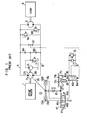
- a prime mover 1 is connected to a variable displacement hydraulic pump 2 driven by the prime mover 1.
- the numeral 3 designates a hydraulic actuator which is connected to the pump 2 via conduits A and B.
- the variable displacement hydraulic pump 2 has two ports 2A and 2B and is of the type capable of reversing the direction in which the fluid is delivered by the pump 2.
- the pump 2 may be of a swash plate type or a swash shaft type axial plunger pump, for example.
- the hydraulic pump 2 comprises .a movable member 2c for deciding the displacement of the pump, which may be a swash plate or a swash shaft, for example, and provides a flow rate of the pump 2 which may vary depending on a displacement or an angle of inclination (hereinafter referred to as a tilt) with respect to a neutral position of the movable member 2c.
- a load 4 is connected to the hydraulic actuator 3.
- The-numeral 5 designates a tank, and the numeral 6 a charge pump driven by the prime mover 1 to supply pressurized fluid for avoiding the occurrence of a cavitation in the conduits A and B.
- the numeral 7 is a relief valve for setting a maximum discharge pressure for the charge pump 6.
- Check valves 8A and 8B are mounted in conduits connecting the charge pump 6 to the conduits A and B respectively.
- Relief valves 9A and 9B set maximum pressures for the conduits A and B respectively.
- the numeral_10 is a shuttle valve which selects the higher one of the pressures in the conduits A and B.
- the numeral 11 is a pilot pump for supplying pressurized fluid for controlling the tilt of the pump 2.
- the numeral 13 is a cylinder for manipulating the movable member 2c of the pump 2 which has pressure receiving chambers 13A and 13B in which springs 13a and 13b are respectively mounted.
- the numeral 14 is a servo valve for suitably switching a pressurized fluid supply conduit and a conduit communicating with the tank between the two pressure receiving chambers 13A and 13B of the cylider 13.
- the servo valve 14 has connected thereto a manipulating lever 14a which manipulates the servo valve 14 to give a tilt target value XL, to the pump 2.
- the servo valve 14 includes a sleeve 14b which has its position relative to a spool of the servo valve 14 changed by a feedback signal.
- the numeral 15 is a feedback link connected to a piston rod of the cylinder 13 and the sleeve 14b, for transmitting a displacement of the piston rod to the sleeve 14b.
- the numeral 16 is a change-over valve for switching a supply conduit for the servo valve 14 between the pilot valve 11 and the tank 5 in accordance with the pressure from the shuttle valve 10.
- a spring 16a performs the function of returning the spool of the servo valve 14 to a neutral position by overcoming the force of the pressurized fluid from the shuttle valve 10.
- a sleeve l6b has its position relative to a spool of the change-over valve 16 changed by a feedback signal.
- a spring 16c applies an offset load to the sleeve 16b.
- the numeral 17 is a cam which is displaced by the feedback link 15.
- the numeral 18 is a rod positioned against the cam 17 for causing the sleeve 16b to be displaced in accordance with the shape of the cam 17.
- variable displacement hydraulic pump 2 driven by the prime mover 1 and the hydraulic actuator 3 connected to the load 4 are connected together to provide a closed circuit, and the operation of the hydraulic actuator 3 is controlled by controlling the tilt of the pump 2.
- control or pump tilt control is effected as presently to be described. Assume that a positive load is applied, with the port 2A being on the discharge side. In other words, assume that the flow rate of the pump 2 is increased from zero to drive the load, with the port 2A being a discharge port, so that the discharge pressure at the port 2A will be increased. In this case, the manipulating lever 14a of the servo valve 14 is actuated to switch the servo valve 14 to a position 14A. This allows the pressurized fluid supplied from the pump 11 to flow into one pressure receiving chamber 13A of the cylinder 13 via the change-over valve 16 and servo valve 14.
- the piston of the cylinder 13 moves rightwardly to increase the tilt of the pump 2 in such a manner that the flow rate discharged from the port 2A increases.
- This increase in the tilt of the pump 2 is fed back by the feedback link 15 to the sleeve l4b of the servo valve 14 and the piston rod of the cylinder 13 stops moving when the tilt of the pump 2 has reached the manipulated variable of the manipulating lever 14a or the tilt target value XL, so long as the change-over valve 16 is switched.
- the discharge pressure on the port 2A side rises to drive the load 4 and is supplied to the change-over valve 16 via the shuttle valve 10.
- the change-over valve 16 is switched. This brings the two pressure receiving chambers 13A and 13B into communication with the tank 5, even if the servo valve 14 is in the position 14A.
- the piston and therefore the tilt of the pump 2 are urged toward the neutral position, due to the biasing forces of the springs 13a and 13b of the cylinder 13, so that the flow rate is decreased.
- the discharge pressure is controlled in a manner to prevent it from exceeding a switching pressure Pc of the change-over valve 16 prevailing at this time.
- the switching pressure Pc is decided by the position of the sleeve 16b of the change-over valve 16 and the characteristic of the spring 16a.
- the mechanism including the feedback link 15, cam 17 and rod 18 as shown in Fig. 1 for example, it is possible to decide the switching pressure Pc or the maximum value of the prevailing discharge pressure of the pump 2 in accordance with the tilt by feeding back a change in the tilt of the pump 2 to the sleeve 16b of the change-over valve 16, to thereby effect control of the force or torque necessary for driving the hydraulic pump 2.
- the control characteristic for the input of the hydraulic pump 2 can be set as desired by changing the shape of the cam 17, so as to obtain a constant input torque, for example.
- the switching pressure Pc of the change-over valve 16 shows a maximum set value P CMAX when the rod 18 is located at the bottom of a recess of the cam 17, as shown in Fig. 1.
- the tilt of the pump 2 continues to decrease toward the neutral position until finally it reaches a minimum value necessary for keeping the P CMAX .
- the servo valve 14 shifts to a position l4B to supply pressurized fluid to the pressure receiving chamber 13B of the cylinder 13 while the pressure receiving chamber 13A communicates with the tank 5, so that the piston of the cylinder 13 moves leftwardly and the tilt of the pump 2 is returned to the neutral position.
- the load 4 tries to continue to move at the same velocity by its own inertia, so that the hydraulic actuator 3 performs a pumping action to generate a pressure at the port 2B of the pump 2 which is on the suction side.
- the change-over valve 16 is actuated to cut off the supply of the pressurized fluid to the servo valve 14, so that the pressure receiving chambers 13A and 13B of the cylinder 13 both communicate with the tank 5.
- the piston and the tilt of the pump 2 still continue to move toward the neutral position by the biasing forces of the springs 13a and 13b of the cylinder 13, so that the pressure on the suction side will further rise until the relief valve 19 is opened.
- the tilt of the pump 2 returns to the neutral position while the pressurized fluid from the hydraulic actuator 3 is released from the relief valve 9B. That is, the brake is applied to the load 4 as its energy of inertia is consumed through the relief valve 9B. Thus no power or energy is recovered.
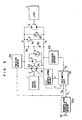
- Fig. 3 shows in a circuit diagram a first example of the hydrostatic drive system for which the control method according to the invention is carried into practice.
- Figs. 3 and 5 parts similar to those shown in Fig. 1 are designated by like reference characters, and in the following description only those parts which are not shown in Fig. 1 will be described.
- the numeral 20 designates a single- rod cylinder having a piston 20c connected to the movable member 2c for manipulating the tilt of the hydraulic pump 2.
- the cylinder 20 has a head side chamber 20a and a rod side chamber 20b into which is introduced the pressurized fluid from the pilot pump 11.
- the numeral 21 designates a servo valve adapted to be moved by a manipulating lever 21a as it is operated to actuate the cylinder 20.
- 21b is a sleeve for receiving a feedback signal.
- 22 is a feedback link connected at one end to a rod of the cylinder 20 and at the other end to the sleeve 21b, to feed back the tilt of the pump 2 to the servo valve 21..
- 23 is a change-over valve mounted in a passageway from the servo valve 21 to the tank 5 and a. passageway from the pilot pump 11 to the rod side chamber 20a of the cylinder 20, to be actuated by a pilot pressure from the conduit B.
- 23a is a spool returnign spring,-23b a sleeve and 23c a sleeve returning spring.
- 24 is another change-over valve mounted in a passageway from the pump 11 to the servo motor 21 and a passageway from the head side chamber 20a of the cylinder 20 to the tank 5, to be actuated by a pilot pressure from the conduit A.
- 24a is a spool returning spring, 24b a sleeve and 24c a sleeve returning spring.
- 25 is a cam connected to the feedback link 22, and 26 and 27 are rods positioned against the cam 25.
- the sleeves 23b and 24b can be displaced depending on the shape of the cam 25.
- Control is effected in the hydrostatic drive system of the aforesaid construction as follows. First of all, control effected when the load is positive and pressurized fluid is discharged through the port 2A of the pump 2 will be described. That is, when the manipulating lever 21a is switched to a position 21A in the condition in which the load 4 is stationary, the pressurized oil supplied from the pump 11 via the change-over valve 24 flows into the head side chamber 20a of the cylinder 20. The head side chamber 20a and the rod side chamber 20b being brought to the same pressure, the difference in area between the opposite sides of'the piston 20c moves the piston 20c rightwardly to thereby increase the tilt of the pump 2 and discharge the pressurized fluid through the port 2A.
- the discharged fluid actuates the hydraulic actuator 3 to drive the load 4. Meanwhile this increase in the pump tilt is fed back to the sleeve 21b via the feedback link 22, so that the pump tilt increases to a value commensurate with the manipulated variable achieved by the manipulating lever 21a.
- discharge pressure is increased in the conduit A on the discharge side, and this pressure is introduced into the change-over valve 24 as a switching and pilot pressure.
- Pc which is decided by the characteristic of the spring 24a and the position of the sleeve 24b or the shape of the cam 25, the change-over valve 24 is switched.
- the passageway through which the pressurized fluid from the pump 11 is supplied is blocked by the change-over valve 24 and the passageway from the head side chamber 20a communicates with the tank 5, so that the piston 20c of the cylinder 20 is moved leftwardly by the pressurized fluid in the rod side chamber 20b, to thereby return the tilt of the pump 2 toward neutral.
- the rate of increase in the tilt is controlled so that the switching pressure Pc may not be exceeded by the discharge pressure.
- the discharge pressure is decided by the shape of the cam 25 to which the rod 27 is brought into contact.
- the aforesaid description refers to the condition in which the port 2A of the hydraulic pump 2 functions as a discharge port.
- the operation shows no change from what has been described when the port 2B functions as a discharge port.
- the rate of increase in the tilt of the pump 2 effected when the flow rate of the pump 2 is increased is controlled by means of the change-over valve 23.
- the discharge pressure-flow rate characteristic is decided by a planar portion 25f and an inclined portion 25d of the cam 25.
- the rate of decrease in the flow rate of the pump is decided by the change-over valve 24 when the flow rate of the pump 2 is reduced, and at this time the suction pressure-flow rate characteristic is decided by a planar portion 25e and a portion 25c adjacent thereto of the cam 25.
- the portion 25c is formed to be planar, so that the suction pressure is controlled to be a constant pressure P CMAX , regardless of the value of the flow rate of the delivery by the pump 2.
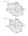
- Fig. 4 shows one example of the control characteristic described hereinabove.
- the maximum pressure is P CMAX and the maximum value of the discharge pressure is controlled along a constant torque curve T as the pump tilt increases.
- the suction pressure has a maximum value of P CMAX regardless of the pump tilt.
- Fig. 5 is a circuit diagram of a second example of the hydrostatic drive system with which the control method according to the invention is carried into practice.
- 30 is a manipulating lever which gives the tilt target value X L to the pump 2
- 30a is a manipulated variable sensor sensing the manipulated variable achieved by the manipulating lever 30 and supplying a tilt target value signal X L .
- 31A and 31B are pressure sensors for sensing the pressures in the conduits A and B and supplying pressure signals P A and P B respectively.
- 32 is tilt manipulating means for manipulating the tilt of the pump 2 in accordance with a tilt manipulation command signal Y subsequently to be described and sensing the tilt of the 'pump 2 to supply a tilt signal Z.
- the arithmetic unit 33 is an arithmetic unit to which are connected the manipulated variable sensor 30a, pressure sensors 31A, 31B and tilt manipulating means 32 and into which the tilt target signal X L , tilt signal Z, pressure signal P A and pressure signal P B are fed.
- the arithmetic unit 33 produces a tilt manipulation command signal Y and feeds same into the tilt manipulating means 32.
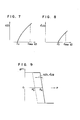
- Fig. 6 is a flow chart indicating the steps to be followed in chronological sequence
- Figs. 7 - 9 are chara- characteristic diagrams showing functional relations previously set.
- the arithmetic unit 33 is a microcomputer, and in the interest of clarity the description will first refer to a case in which steps 58, 59, 60 and 61 shown in Fig. 6 are eliminated.
- the tilt target X Ll tilt Z and pressures P A and P B are read into the arithmetic unit 33 in steps 40, 41, 42 and 43.
- the neutral position of the pump 2 shown in Fig. 5 is set at 0, the direction of a tilt in which the port 2A is placed on the discharge side is positive and the direction of a tilt in which the port 2B is placed on the discharge side is negative, for the convenience of description.
- step 46 the process transfers to step 46 in which the value of the pressure P A in the conduit A is adopted as P. Then in step 47, whether the tilt Z is positive or negative or the discharge direction of the pump 2 is judged. If the tilt Z is negative, since E > 0, this condition shows that the load is negative and the flow rate of the delivery by the pump 2 through the port 2B should be reduced to control the load 4. In this case, the process transfers to step 50 (assuming that steps 58 and 59 do not exist), and a function g(P), subsequentely to be described, which is set beforehand is read out and substituted for an increment ⁇ X of the tilt command X L in step 51.
- step 47 if the result of the judgment in step 47 is Z > 0, then it is indicated that the condition is that of positive load requiring to increase the flow rate of the pump 2 through the port 2A to accelerate the load 4.
- the process transfers to step 48, and a function f(
- processing is carried out in step 50 et seq. in the same manner as described.hereinabove.
- ) is set previously in such a manner that it is functionally related to Z as shown in Fig. 7.
- step 45 When the result of the judgment performed in step 45 is e ⁇ 0, the process shifts to step 52 in which processing for changing the pressure P to P B takes place.
- step 53 whether the tilt Z is positive or negative is judged, and the process shifts to step 56 when Z > 0 (steps 60 and 61 being considered nonexisting). This indicates the condition of a negative load in which the port 2A is on the discharge side and it is required to brake the load by reducing the tilt Z of the pump 2 or reducing the flow rate of the pump 2 through the port 2A.
- step 56 processing is carried out in such a manner that a function g(P) is read out to determine an increment ⁇ X based on the function g(P), in the same manner as described previously.
- the function g(P) has its sign changed and the increment AX is determined. Then after shifting to step 62, steps 64, 65 and 66 are successively followed if ⁇ 0.
- the maximum value of the suction pressure P B is limited to Po. This characteristic corresponds to the characteristic of the second quadrant shown in Fig. 4.
- step 53 When Z ⁇ 0 in step 53, this indicates the condition of a positive load in which the load 4 is accelerated by shifting the tilt Z of the pump 2 in a direction in which the flow rate of the pump 2 through the port 2A increased or shift the tilt Z toward a maximum negative value.
- step 54 the function f(
- step 56 the function g(P) is read out in the same manner as described hereinabove. Thereafter steps 57, 62, 64, 65 and 66 are followed.
- steps 58, 59, 60 and 61 have been eliminated.
- steps 58 and 59 for reading out a function f'(
- steps 60 and 61 for adding the function f'(
- ) as shown in the characteristic diagram shown in Fig. 8 and carry out torque limitations as indicated by a broken line in Fig. 9.
- control method according to the invention for a hydrostatic drive sytem enables, when the flow rate of a variable displacement hydraulic pump forming a part of a closed hydraulic fluid circuit is increased, the rate of change in the tilt of the pump or the flow rate of the pump to be controlled in such a manner that the discharge pressure may not exceed a first set of values set beforehand with respect to the flow rate of the pump.
- the flow rate of the pump is decreased, it enables the rate of change in the tilt of the pump or the flow rate of the pump to be controlled in such a manner that the suction pressure may not exceed a second set of values set beforehand with respect to the flow rate of the pump.
- the invention makes it possible to avoid a loss of energy due to the pressurized fluid being relieved as in the prior art in the case of a positive load, to effect input limitations, and to effect torque limitations in the case of a negative load having a characteristic different from the characteristic obtained in the case of a positive load or to optimize the characteristic so that impact is minimized while a required braking distance and an efficient energy recovery can be achieved. It is also possible to do without torque limitations. In this case, the braking distance is shortened and the braking characteristic can be improved, thereby further increasing the energy recovery efficiency.
Landscapes
- Engineering & Computer Science (AREA)
- General Engineering & Computer Science (AREA)
- Mechanical Engineering (AREA)
- Physics & Mathematics (AREA)
- Fluid Mechanics (AREA)
- Fluid-Pressure Circuits (AREA)
- Control Of Positive-Displacement Pumps (AREA)
- Control Of Fluid Gearings (AREA)
Applications Claiming Priority (2)
| Application Number | Priority Date | Filing Date | Title |
|---|---|---|---|
| JP144280/80 | 1980-10-17 | ||
| JP55144280A JPS605821B2 (ja) | 1980-10-17 | 1980-10-17 | 油圧駆動装置の制御方法 |
Publications (3)
| Publication Number | Publication Date |
|---|---|
| EP0050318A2 true EP0050318A2 (de) | 1982-04-28 |
| EP0050318A3 EP0050318A3 (en) | 1983-03-16 |
| EP0050318B1 EP0050318B1 (de) | 1988-04-27 |
Family
ID=15358401
Family Applications (1)
| Application Number | Title | Priority Date | Filing Date |
|---|---|---|---|
| EP81108363A Expired EP0050318B1 (de) | 1980-10-17 | 1981-10-15 | Regelverfahren und Regelsystem für hydrostatische Getriebe |
Country Status (5)
| Country | Link |
|---|---|
| US (1) | US4451893A (de) |
| EP (1) | EP0050318B1 (de) |
| JP (1) | JPS605821B2 (de) |
| KR (1) | KR850001835B1 (de) |
| DE (1) | DE3176721D1 (de) |
Families Citing this family (6)
| Publication number | Priority date | Publication date | Assignee | Title |
|---|---|---|---|---|
| JPS60175863A (ja) * | 1984-02-20 | 1985-09-10 | Sekitan Rotenbori Kikai Gijutsu Kenkyu Kumiai | 可変容量ポンプの馬力制御方法 |
| US6758356B1 (en) | 1989-10-10 | 2004-07-06 | Manitowoc Crane Companies, Inc. | Liftcrane with synchronous rope operation |
| US5189605A (en) * | 1989-10-10 | 1993-02-23 | The Manitowoc Company, Inc. | Control and hydraulic system for a liftcrane |
| US5579931A (en) * | 1989-10-10 | 1996-12-03 | Manitowoc Engineering Company | Liftcrane with synchronous rope operation |
| KR950019129A (ko) * | 1993-12-30 | 1995-07-22 | 김무 | 유압식 건설기계의 엔진-펌프 제어장치 및 방법 |
| US8543245B2 (en) * | 2009-11-20 | 2013-09-24 | Halliburton Energy Services, Inc. | Systems and methods for specifying an operational parameter for a pumping system |
Family Cites Families (12)
| Publication number | Priority date | Publication date | Assignee | Title |
|---|---|---|---|---|
| DE1107523B (de) * | 1956-12-21 | 1961-05-25 | Dowty Hydraulic Units Ltd | Regelbares hydrostatisches Getriebe, insbesondere fuer Kraftfahrzeuge |
| JPS5426663B1 (de) * | 1968-05-23 | 1979-09-05 | ||
| US3585797A (en) * | 1969-06-09 | 1971-06-22 | Sundstrand Corp | Hydrostatic transmission displacement control |
| DE2208172C3 (de) * | 1972-02-22 | 1974-07-11 | Karl Dipl.-Ing. 7024 Bernhausen Schlecht | Vorrichtung zur Dämpfung des belastungsbedingten Druckanstiegs bei hydrostatischen Antrieben |
| JPS5320621B2 (de) * | 1973-11-17 | 1978-06-28 | ||
| GB1508642A (en) * | 1974-02-28 | 1978-04-26 | Eaton Corp | Hydrostatic transmission control system |
| US3994623A (en) * | 1975-02-11 | 1976-11-30 | Compressor Controls Corporation | Method and apparatus for controlling a dynamic compressor |
| US4108574A (en) * | 1977-01-21 | 1978-08-22 | International Paper Company | Apparatus and method for the indirect measurement and control of the flow rate of a liquid in a piping system |
| US4164035A (en) * | 1977-09-14 | 1979-08-07 | Sundstrand Corporation | Surge control for variable speed-variable geometry compressors |
| FR2408775A1 (fr) * | 1977-11-15 | 1979-06-08 | Rexroth Sigma | Perfectionnements apportes aux transmissions hydrostatiques pour vehicules, et vehicules equipes de telles transmissions |
| US4227862A (en) * | 1978-09-19 | 1980-10-14 | Frick Company | Solid state compressor control system |
| US4218191A (en) * | 1978-11-29 | 1980-08-19 | Phillips Petroleum Company | Multi-constraint control of a compression system |
-
1980
- 1980-10-17 JP JP55144280A patent/JPS605821B2/ja not_active Expired
-
1981
- 1981-10-15 DE DE8181108363T patent/DE3176721D1/de not_active Expired
- 1981-10-15 EP EP81108363A patent/EP0050318B1/de not_active Expired
- 1981-10-16 KR KR1019810003915A patent/KR850001835B1/ko not_active Expired
- 1981-10-16 US US06/311,969 patent/US4451893A/en not_active Expired - Fee Related
Also Published As
| Publication number | Publication date |
|---|---|
| EP0050318A3 (en) | 1983-03-16 |
| JPS5769161A (en) | 1982-04-27 |
| KR850001835B1 (ko) | 1985-12-26 |
| EP0050318B1 (de) | 1988-04-27 |
| DE3176721D1 (en) | 1988-06-01 |
| JPS605821B2 (ja) | 1985-02-14 |
| KR830008077A (ko) | 1983-11-09 |
| US4451893A (en) | 1984-05-29 |
Similar Documents
| Publication | Publication Date | Title |
|---|---|---|
| US4528813A (en) | Control system for hydrostatic power transmission | |
| EP0041273B1 (de) | Druckregeleinrichtung für ein hydrostatisches Getriebe | |
| KR950007624B1 (ko) | 유압펌프의 제어장치 | |
| EP2123947B1 (de) | Fahrsteuervorrichtung für hydraulikfahrzeug | |
| US5085051A (en) | Displacement of variable displacement pump controlled by load sensing device having two settings for low and high speed operation of an actuator | |
| EP0614016B1 (de) | Hydraulische antriebsvorrichtung einer hydraulischen baumaschine | |
| EP0411151B1 (de) | Hydraulische schaltung für maschinen | |
| JP2010025179A (ja) | 走行作業機械の油圧駆動システム | |
| US5398507A (en) | Hydraulic circuit system | |
| EP0439621B1 (de) | Zufuhrschaltungsvorrichtung für öl unter druck zum hydraulischem kolben einer baustellenvorrichtung | |
| US5197860A (en) | Hydraulic apparatus for construction machines | |
| US5279122A (en) | Hydraulic circuit apparatus for supplying fluid under pressure into hydraulic cylinders for work implement | |
| EP0312275B1 (de) | Stufenlos regelbares Getriebe | |
| EP0050318A2 (de) | Regelverfahren und Regelsystem für hydrostatische Getriebe | |
| EP1398512B1 (de) | Hydraulische antriebseinheit einer arbeitsmaschine, und hydaulisches antriebsverfahren | |
| EP0491944B1 (de) | Geschwindigkeitsschaltanordnung eines laufenden hydraulischen motors | |
| GB2291986A (en) | Fluid pressure control system for hydraulic excavators | |
| EP0084835B1 (de) | Antrieb | |
| EP1231387A2 (de) | Verfahren und Einrichtung zur Druckregelung in einer hydraulisch betätigten Vorrichtung | |
| JPS638317B2 (de) | ||
| JP2786941B2 (ja) | 作業機械の油圧駆動装置 | |
| EP0279152A1 (de) | Verfahren und Vorrichtung, um das hydraulische System einer Grabemaschine zu kontrollieren | |
| JPH0723588Y2 (ja) | 可変ポンプの流量調整弁装置 | |
| JPH11210879A (ja) | 油圧駆動車両の制御装置 | |
| JPH06249208A (ja) | 建設機械の油圧駆動装置 |
Legal Events
| Date | Code | Title | Description |
|---|---|---|---|
| PUAI | Public reference made under article 153(3) epc to a published international application that has entered the european phase |
Free format text: ORIGINAL CODE: 0009012 |
|
| AK | Designated contracting states |
Designated state(s): DE FR |
|
| PUAL | Search report despatched |
Free format text: ORIGINAL CODE: 0009013 |
|
| AK | Designated contracting states |
Designated state(s): DE FR |
|
| 17P | Request for examination filed |
Effective date: 19830510 |
|
| GRAA | (expected) grant |
Free format text: ORIGINAL CODE: 0009210 |
|
| AK | Designated contracting states |
Kind code of ref document: B1 Designated state(s): DE FR |
|
| REF | Corresponds to: |
Ref document number: 3176721 Country of ref document: DE Date of ref document: 19880601 |
|
| ET | Fr: translation filed | ||
| PLBE | No opposition filed within time limit |
Free format text: ORIGINAL CODE: 0009261 |
|
| STAA | Information on the status of an ep patent application or granted ep patent |
Free format text: STATUS: NO OPPOSITION FILED WITHIN TIME LIMIT |
|
| 26N | No opposition filed | ||
| PGFP | Annual fee paid to national office [announced via postgrant information from national office to epo] |
Ref country code: FR Payment date: 19940818 Year of fee payment: 14 |
|
| PGFP | Annual fee paid to national office [announced via postgrant information from national office to epo] |
Ref country code: DE Payment date: 19941230 Year of fee payment: 14 |
|
| PG25 | Lapsed in a contracting state [announced via postgrant information from national office to epo] |
Ref country code: FR Effective date: 19960628 |
|
| PG25 | Lapsed in a contracting state [announced via postgrant information from national office to epo] |
Ref country code: DE Effective date: 19960702 |
|
| REG | Reference to a national code |
Ref country code: FR Ref legal event code: ST |