EP0049829A2 - Apparatus for making a package of the two-compartment bag type - Google Patents
Apparatus for making a package of the two-compartment bag type Download PDFInfo
- Publication number
- EP0049829A2 EP0049829A2 EP81107840A EP81107840A EP0049829A2 EP 0049829 A2 EP0049829 A2 EP 0049829A2 EP 81107840 A EP81107840 A EP 81107840A EP 81107840 A EP81107840 A EP 81107840A EP 0049829 A2 EP0049829 A2 EP 0049829A2
- Authority
- EP
- European Patent Office
- Prior art keywords
- shafts
- bag
- machine according
- units
- shaft
- Prior art date
- Legal status (The legal status is an assumption and is not a legal conclusion. Google has not performed a legal analysis and makes no representation as to the accuracy of the status listed.)
- Withdrawn
Links
Images


Classifications
-
- B—PERFORMING OPERATIONS; TRANSPORTING
- B65—CONVEYING; PACKING; STORING; HANDLING THIN OR FILAMENTARY MATERIAL
- B65B—MACHINES, APPARATUS OR DEVICES FOR, OR METHODS OF, PACKAGING ARTICLES OR MATERIALS; UNPACKING
- B65B29/00—Packaging of materials presenting special problems
- B65B29/02—Packaging of substances, e.g. tea, which are intended to be infused in the package
- B65B29/028—Packaging of substances, e.g. tea, which are intended to be infused in the package packaging infusion material into filter bags
Abstract
Bei einer Maschine (1) zur Herstellung von beutelartigen Zweikammerpackungen aus einer schmiegsamen aufgußfähigen Werkstoffbahn (5), insbesondere von Teebeuteln, die durch Faltung gebildet und durch Klammern verschlossen werden, sind zur Steuerung der beweglichen Teile der einzelnen Aggregate (37, 38, 61, 62, 74, 75, 106) einer Arbeitssttion (A) achsparallel nebeneinander angeordnete, verschiebbar und/oder verdrehbar gelagerte Wellen (31, 32, 51, 52, 71, 101, 111) als Betätigungsglieder vorgesehen, die unmittelbar oder über Zwischenglieder durch innerhalb des Transportmittels (2) oder seitlich neben dieden angeordneter Kurvenlineale (33, 34, 53, 54, 72, 102, 112) oder ähnlicher Steuermittel betätigbar und die mit den beweglichen Teilen des Aggregates koppelbar sind. Außerdem sind die Wellen jeweils gemeinsam in einem oder mehreren von den beweglichen Teilen der Aggregate räumlich getrennten abgeschlossenen Gehäuse (11) verschiebbar und oder drehbar gelagert. Durch diese Ausgestaltung wird die Verpackungskapazität einer Maschine erhöht. Außerdem sind die Steuermittel nicht im Arbeitsbereich angeordnet und somit nicht der Verschmutzung unterworfen. Auch sind die Steuerbewegungen der einzelnen Teile leicht und exakt einstellbar.In the case of a machine (1) for producing bag-like two-chamber packs from a flexible infusible material web (5), in particular tea bags, which are formed by folding and closed by clips, the movable parts of the individual units (37, 38, 61, 62, 74, 75, 106) of a work station (A) axially parallel to each other, slidably and / or rotatably mounted shafts (31, 32, 51, 52, 71, 101, 111) provided as actuators, which directly or via intermediate links through inside of the transport means (2) or laterally next to the curve rulers (33, 34, 53, 54, 72, 102, 112) or similar control means which can be coupled to the moving parts of the unit. In addition, the shafts are each displaceably and or rotatably mounted together in one or more closed housings (11) which are spatially separated from the moving parts of the units. This configuration increases the packaging capacity of a machine. In addition, the control means are not arranged in the work area and are therefore not subject to contamination. The control movements of the individual parts are also easily and precisely adjustable.
Description
Die Erfindung bezieht sich auf eine Maschine zur Herstellung von beutelartigen Zweikammerpackungen aus einer schmiegsamen aufgußfähigen Werkstoffbahn, insbesondere von Teebeuteln, die durch Faltung gebildet und durch Klammern verschlossen sind, wobei die Werkstoffbahn mit unterteilten Füllgutportionen gefüllt und zu einem Schlauch gefaltet kontinuierlich zuläuft und auf einem kontinuierlich umlaufenden Transportmittel steuerbare Fertigungsaggregate als Arbeitsstationen angeordnet sind, die jeweils von außerhalb der Transportbahn installierte Mittel steuerbar sind und von denen jedes Aggregat Falzelemente zur Bildung des Beutelbodens und des Beutelkopfes, zwei Aufstellarme zum Aufrichten der Beutelhälften, in einem der Aufstellarme eine Einrichtung zur Aufnahme des Etiketts sowie Einrichtungen zum abtrennen des Beutelstranges und des mit einem Etikett versehenen Etikettenfadens aufweist. Derartige Maschinen sind durch die DE-PS 21 2o 27o sowie die DE-PS 24 o5 761 bekannt und haben sich in der Praxis außerordentlich gut bewährt. Der Bauaufwand zur Betätigung der einzelnen Aggregate der Arbeitsstationen, die bei der Ausgestaltung nach der DE-PS 21 2o 27o ortsfest angeordnet sind, nach der DE-PS 24 o5 761 dagegen auf einem Transportmittel, das nacheinander die einzelnen Funktionszonen durchläuft, ist hierbei jedoch außerordentlich groß. Außerdem sind die Steuerelemente jeweils in unmittelbarer Nähe des Arbeitsplatzes angeordnet, so daß das zu verpackende Gut unumgänglich auf diese fällt. Dies führt oftmals zu Störungen und Betriebsunterbrechungen, da die meist klein bauenden ineinander integrierten Antriebsteile sehr staubempfindlich sind. Des weiteren sind auf diese Weise jeweils nur die Betätigungsglieder einer Arbeitsstation zu steuern.The invention relates to a machine for producing bag-like two-chamber packs from a flexible infusible material web, in particular tea bags, which are formed by folding and closed by clips, the material web being filled with divided portions of filling material and folded into a tube, running continuously and continuously Circulating means of transport controllable manufacturing units are arranged as workstations, each of which can be controlled from means installed outside the transport path and of which each unit folding elements for forming the bag bottom and the bag head, two arms for erecting the halves of the bag, in one of the arms a device for receiving the label as well as devices for separating the string of bags and the label thread provided with a label. Such machines are known from DE-PS 21 2o 27o and DE-PS 24 o5 761 and have proven themselves extremely well in practice. The construction effort for actuating the individual units of the workstations, which are arranged in a fixed manner in the embodiment according to DE-PS 21 20 27o, according to DE-PS 24 o5 761, on the other hand, on a means of transport that passes through the individual functional zones one after the other is extraordinary large. In addition, the control elements are each arranged in the immediate vicinity of the workplace, so that the goods to be packaged inevitably fall on them. This often leads to malfunctions and operational interruptions, since the mostly small, integrated drive components are very sensitive to dust. Furthermore, only the actuators of a work station can be controlled in this way.
Es ist daher Aufgabe der Erfindung, eine Maschine zur Herstellung von beutelartigen Zweikammerpackungen zu schaffen, bei der die Steuerelemente nicht im eigentlichen Arbeitsbereich der Maschine angeordnet, sondern räumlich von den einzelnen Betätigungsgliedern getrennt sind, so daß der Funktionsablauf nicht durch das zu verpackende Gut beeinträchtigt werden kann. Des weiteren sollen die zur Verstellung der einzelnen Aggregate erforderlichen Bewegungsabläufe auf einfache Grundbewegungen ohne komplizierte störanfällige übertragungsmechanismen zurückgeführt werden, dennoch soll eine funktionssichere und folgerichtige Betätigung gewährleistet sein. Vor allem aber soll es aufgrund der Ausgestaltung der Steuermittel und der Übertragungsglieder möglich sein, ohne wesentlichen zusätzlichen Bauaufwand die Aggregate mehrerer nebeneinander angeordneter Arbeitsstationen gleichzeitig zu betätigen, so daß mit einer Maschine mehrere Verpackungen zu gleicher Zeit hergestellt werden können.Ferner soll insgesamt der Fertigungsaufwand in einem erheblichen Maße geringer als bei den bisher bekannten vergleichbaren Maschinen gehalten werden und es soll eine hohe Betriebssicherheit gegeben sein.It is therefore an object of the invention to provide a machine for producing bag-like two-chamber packs in which the control elements are not arranged in the actual working area of the machine, but are spatially separated from the individual actuators, so that the functional sequence is not impaired by the goods to be packaged can. Furthermore, the movement sequences required for the adjustment of the individual units are to be traced back to simple basic movements without complicated transmission mechanisms which are susceptible to faults, nevertheless a functionally reliable and consistent operation should be guaranteed. Above all, however, due to the design of the control means and the transmission elements, it should be possible to operate the units of several workstations arranged side by side at the same time without any significant additional construction work, so that several packaging units can be produced at the same time are kept to a considerable extent less than in the previously known comparable machines and there should be a high level of operational reliability.
Gemäß der Erfindung wird dies dadurch erreicht, daß zur Steuerung der beweglichen Teile der einzelnen Aggregate einer Arbeitsstation achsparallel nebeneinander angeordnete, verschiebbar und/oder verdrehbar gelagerte Wellen als Betätigungsglieder vorgesehen sind, die unmittelbar oder über Zwischenglieder durch innerhalb des Transportmittels oder seitlich neben diesen angeordneter Kurvenlineale oder ähnlicher Steuermittel betätigbar und die mit den beweglichen Teilen des Aggregates koppelbar sind.According to the invention, this is achieved in that for the control of the moving parts of the individual units of a work station axially parallel, slidably and / or rotatably mounted shafts are provided as actuators, which are arranged directly or via intermediate elements by means of curved rulers arranged inside the transport means or laterally next to them or similar control means can be operated and which can be coupled to the moving parts of the unit.
Zweckmäßig ist es hierbei, die Wellen der Aggregate einer Arbeitsstation jeweils gemeinsam in einem oder mehreren von den beweglichen Teilen der Aggregate getrennten Gehäuse verschiebbar und/oder drehbar zu lagern.It is expedient here for the shafts of the units of a work station to be displaceably and / or rotatably mounted together in one or more housings separate from the moving parts of the units.
Sehr vorteilhaft ist es des weiteren, zwei oder mehrere gleiche Arbeitsstationen nebeneinander auf dem Transportmittel anzuordnen und die beweglichen Teile der nebeneinander angeordneten Aggregate gemeinsam mittels durchgehender achsparalleler Wellen als Betätigungsglieder zu steuern bzw. die einzelnen beweglichen Teile miteinander zu koppeln..Auf diese Weise ist es möglich, mit geringem Aufwand eine Verdoppelung bzw. eine Vervielfachung der Verpackungskapazität einer Maschine zu erreichen.It is also very advantageous to arrange two or more identical workstations next to each other on the means of transport and to control the moving parts of the units arranged next to one another by means of continuous axially parallel shafts as actuators or to couple the individual moving parts to each other. In this way it is possible to achieve a doubling or a multiplication of the packaging capacity of a machine with little effort.
Die die Betätigungsglieder aufnehmenden Gehäuse können ein-oder beidseitig der einzelnen Arbeitsstationen, bei mehreren nebeneinanderliegenden Arbeitsstationen vorzugsweise zwischen diesen, angeordnet werden, so daß stets eine einwandfreie Lagerung der Wellen gewährleistet ist.The housings receiving the actuators can be arranged on one or both sides of the individual workstations, in the case of a plurality of workstations lying next to one another, preferably between them, so that the shafts are always properly supported.
Als Transportmittel können in einfacher Weise zwei oder mehrere über antreibbare Kettenräder geführte, endlose Gelenkketten vorgesehen werden, an denen die die Betätigungsglieder aufnehmenden Gehäuse befestigt sind.As a means of transport, two or more endless link chains guided over drivable sprockets can be provided in a simple manner, to which the housings receiving the actuators are fastened.
Zum Abtrennen der Werkstoffbahn ist es angebracht, zwei an einer verschiebbaren Welle angelenkte Scherenarme vorzusehen, die durch einen Gelenkzapfen drehbar miteinander verbunden sind, und dem Gelenkzapfen einen ortsfesten, vorzugsweise an dem die verschiebbare Welle aufnehmenden Gehäuse angebrachten Anschlag zuzuordnen, an dem der Gelenkzapfen bei einem durch eine Axialverschiebung der Welle auszuführenden Schnittvorgang anliegt.To separate the material web, it is appropriate to provide two scissor arms articulated on a displaceable shaft, which are rotatably connected to one another by a hinge pin, and to assign a fixed stop, preferably attached to the housing receiving the displaceable shaft, to the hinge pin, on which the hinge pin at one due to an axial displacement of the shaft.
Zur Herstellung des Kopfeinschlages des Beutels sollten zwei winkelförmig ausgebildete Umschläger vorgesehen werden, die getrennt voneinander auf verschiebbaren Wellen als Betätigungsglieder angeordnet sind, wobei mittels der Kurvenlineale und der Wellen die Umschläger auch einzeln derart betätigbar sind, daß zunächst einer der Schlauchteile der Werkstoffbahn an diesem vorbeigeführt wird und daß zur Vornahme einer Faltung um ca. 90° am Beutelkopf bei Durchführung des Beutels unverrückbar gehalten und nachfolgend zur Einfaltung aufeinander zu verschiebbar steuerbar sind.To produce the head wrap of the bag, two angularly shaped envelopes should be provided, which are arranged separately from one another on displaceable shafts as actuators, whereby the envelopes can also be actuated individually by means of the curved rulers and the waves in such a way that first one of the tube parts of the material web leads past it is and that for making a fold of about 90 ° on the bag head when holding the bag immovably held and subsequently controllable for folding to each other are controllable.
An einer der verschiebbaren Wellen, vorzugsweise an einer den Umschlägern zugeordneten Welle, kann hierbei ein Anschlag angebracht werden, mittels dem ein Schnittwerkzeug zum Abtrennen des Etikettenfadens betätigbar ist.In this case, a stop can be attached to one of the displaceable shafts, preferably to a shaft assigned to the envelopes, by means of which a cutting tool for cutting off the label thread can be actuated.
Des weiteren können zur Aufstellung der beiden Beutelteile zwei konzentrisch gelagerte aufeinander zu verschwenkbare Hochschläger vorgesehen werden, die an drehbar in dem Gehäuse aneinander gelagerten Wellen als Betätigungsglieder angebracht sind-yzur Betätigung der einzelnen Wellen ist es ferner angebracht, Einrichtungen zur Umwandlung einer Linearbewegung in eine Rotationsbewegung, beispielsweise an diesen befestigte Zahnräder oder Seilrollen, die mit Zahnstangen bzw. Zugorganen zusammenwirken, Keilgetriebe oder dgl. vorzusehen.Furthermore, two concentric runners that can be pivoted towards one another can be provided for the installation of the two bag parts, which are attached to shafts that are rotatably mounted to one another in the housing as actuators — y for actuating the individual shafts, devices for converting a linear movement into a rotational movement are also appropriate , for example, gears or pulleys attached to these, which interact with toothed racks or traction elements, wedge gears or the like.
Ferner kann zur Vornahme der Bodenfaltung des Beutels durch Zusammenwirken von Faltblechen und Hochschlägern ein mittels einer verschiebbaren Welle als Betätigungsglied in den Bereich des Beutelstranges einführbarer Winkelhebel vorgesehen werden, der verschiebbar auf einer Achse gelagert ist, und wobei zum Anpressen des Beutelstranges durch den Winkelhebel die Achse mittels einer weiteren durch eine Kurvenscheibe sowie eine Zahnstange und einem Zahnrad verdrehbaren Welle als Betätigungsglied verschwenkbar ist. Bei mehreren nebeneinander angeordneten Aggregaten können die Winkelhebel und/oder Achsen und/oder die diese tragenden Bauteile miteinander gekoppelt sein.Furthermore, an angle lever which can be inserted into the area of the bag strand by means of a displaceable shaft as an actuating element and which is displaceably mounted on an axis and can be provided for pressing the bag strand by the angle lever can be provided for the bottom folding of the bag by the interaction of folding sheets and high beaters can be pivoted as an actuating means by means of a further shaft which can be rotated by means of a cam disk and a toothed rack and a toothed wheel. In the case of a plurality of units arranged side by side, the angle levers and / or axles and / or the components carrying them can be coupled to one another.
Die gemäß der Erfindung ausgebildete Maschine zur Herstellung von beutelartigen Zweikammerpackungen ist nicht nur gegenüber den vorbekannten Vorrichtungen dieser Art einfacher in der konstruktiven Ausgestaltung und damit wirtschaftlicher als diese herzustellen, sondern auch vielseitiger einsetzbar und äußerst störunempfindlich. Vor allem aber wird es ermöglicht, die Verpackungskapazität einer Maschine mit nur geringem zusätzlichem Aufwand zu verdoppeln oder zu vervielfachen. Werden nämlich die beweglichen Teile der einzelnen Arbeitsstationen mittels achsparallel angeordneter verschiebbar oder verdrehbar gelagerter Wellen, die mit einem Ende an Kurvenlinealen oder ähnlichen Steuermitteln anliegen, betätigt, so ist es somit möglich, die Steuermittel aus dem Arbeitsbereich herauszunehmen und an Stellen anzuordnen, die nicht durch das zu verpackende Gut beeinträchtigt werden. Durch Verschmutzungen bedingte Betriebsstörungen werden auf diese Weise zuverlässig vermieden.The machine designed according to the invention for the production of bag-like two-chamber packs is not only simpler in terms of construction and thus more economical than producing the known devices of this type, but also more versatile and extremely insensitive to interference. Above all, however, it is possible to double or multiply the packaging capacity of a machine with little additional effort. If the moving parts of the individual work stations are actuated by means of axially parallel, displaceable or rotatably mounted shafts, which abut one end against curved rulers or similar control means, it is thus possible to remove the control means from the work area and to arrange them at locations that are not the goods to be packaged are impaired. In this way, operational disruptions caused by dirt are reliably avoided.
Des weiteren sind die Bewegungen der einzelnen Teile der Aggregate, obwohl die als Betätigungsglieder wirkenden Wellen nur in axialer Richtung verschoben oder gedreht werden, äußerst genau einzustellen und einzuhalten, da durch die Kurvenlineale die jeweils erforderliche Steuerbewegung exakt vorgegeben werden kann. Der dazu erforderliche Bau- und Fertigungsaufwand ist gering, dennoch ist, zumal die Kurvenlineale nicht verschmutzen und auch verschleißfest sind, ein störungsfreier Dauerbetrieb über einen langen Zeitraum gewährleistet.Furthermore, the movements of the individual parts of the units, although the shafts acting as actuators are only moved or rotated in the axial direction, must be set and observed extremely precisely, since the required control movement is precisely specified by the curved rulers can. The construction and manufacturing effort required for this is low, but trouble-free continuous operation over a long period of time is guaranteed, especially since the curve rulers do not become dirty and are also wear-resistant.
Von besonderem Vorteil ist aber bei der erfindungsgemäßen Ausgestaltung, daß mittels einer Welle, die in ihrer Länge beliebig gestaltet werden kann, die bewegbaren Teile mehrerer nebeneinander angeordneter Aggregate gleichzeitig betätigt werden können. Auf diese Weise ist es möglich, zwei oder mehrere Arbeitsstationen auf einer Maschine vorzusehen und diese zu gleicher Zeit arbeiten zu lassen, so daß die Verpackungskapazität vervielfacht wird, ohne daß sich dadurch die für die Überwachung des selbsttätig ablaufenden Verpackungsvorganges erforderlichen Lohnkosten erhöhen. Auf dem Transportmittel sind vielmehr lediglich zusätzliche, in Serie günstig zu fertigende Arbeitsstationen anzubringen, um mit geringen Mittels eine erhebliche Steigerung der Kapazität zu bewerkstelligen.However, it is particularly advantageous in the embodiment according to the invention that the movable parts of a plurality of units arranged side by side can be actuated simultaneously by means of a shaft which can be designed in any length. In this way, it is possible to provide two or more workstations on one machine and to have them work at the same time, so that the packaging capacity is multiplied without increasing the labor costs required for monitoring the automatically running packaging process. Rather, only additional workstations that are cheap to manufacture in series are to be attached to the means of transport in order to achieve a considerable increase in capacity with little resources.
Weitere Einzelheiten der gemäß der Erfindung ausgebildeten Maschine zur Herstellung von beutelartigen Zweikammerpackungen sind den in den dargestellten Ausführungsbeispielen, die nachfolgend im einzelnen erläutert sind, zu entnehmen. Hierbei zeigen:
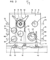
- Fig. 1 eine Maschine mit auf einer angetriebenen Transportkette angeordneten Arbeitsstationen in.whematischer Darstellung,
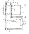
- Fig. 2 das einer Arbeitsstation zugeordnete Gehäuse mit den in diesem gelagerten durch Kurvenlineale zu steuernde Wellen zur Betätigung der beweglichen Teile einer Arbeitsstation in Vorderansicht, sowie
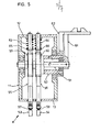
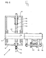
- Fig. 3 bis 7 jeweils in einem achssenkrechten Schnitt die einzelnen den Wellen zugeordneten Aggregate.
- 1 shows a machine with work stations arranged on a driven transport chain in a schematic representation,
- Fig. 2 shows the housing assigned to a work station with the shafts mounted in it to be controlled by curved rulers for actuating the movable parts of a work station in a front view, and
- 3 to 7 each in an axially perpendicular section, the individual aggregates assigned to the shafts.
Die in Fig. 1 mit 1 bezeichnete schematisch dargestellte Maschine zur Herstellung von beutelartigen Zweikammerpackungen aus einer dieser kontinuierlich zugeführten Werkstoffbahn 5, die in nicht gezeigter Weise mit unterteilten Füllgutportionen gefüllt und zu einem Schlauch gefaltet ist, besteht aus einer Gelenkkette 2, die über in einem Maschinenrahmen antreibbar gelagerten Kettenrädern 3 und 4 geführt ist, und einzelnen an der umlaufenden Gelenkkette 2 angebrachten Arbeitsstationen A. Die einzelnen Arbeitsstationen A weisen jeweils die in den Fig. 3 bis 7 dargestellten Aggregate auf, mittels denen die Trennung der Werkstoffbahn 5 in einzelne Abschnitte sowie des Etikettenfadens,die W-förmige Faltung des Beutels 6 und das Aufstellen der gefüllten Beutelteile, die Kopfeinschläge 7, 7' und die Zuführung des Etikettes vorzunehmen sind. Die Bewegungen der verstellbaren Teile der Aggregate werden mittels Kurvenlinealen gesteuert und sind derart aufeinander abgestimmt und gehen so ineinander über, daß durch deren Zusammenwirken in der Maschine 1 selbsttätig aus der Werkstoffbahn 5 fertige Zweikammerbeutel 6 geschaffen werden.The schematically shown in Fig. 1 with 1 machine for the production of bag-like two-chamber packs from a continuously fed
Die Kurvenlineale 33, 34, 53, 54, 72, 102 und 112 zur Steuerung der jeweils in einem kastenförmigen, durch Deckel 12 und 13 staubdicht verschlossenen Gehäuse 11 gelagerten Wellm31, 32,. 51, 52, 71, 101 und 111 sind seitlich neben der Transportkette 2 bzw. zwischen den Kettenrädern 3 und 4 angeordnet, so daß die Wellen teilweise einer Axialbewegung und teilweise einer Drehbewegung unterworfen sind. Außerdem ist es aufgrund dieser Ausgestaltung möglich, mehrere Arbeitsstationen unmittelbar nebeneinander an der Gelenkkette 2 anzubringen, so daß mit geringem zusätzlichem Bauaufwand die Maschine ein Mehrfaches an Verpackungskapazität aufweisen kann.The
Die Wellen 31 und 32 stehen gemäß Fig. 3 mit Umschlägern 37 und 38 in Verbindung und erhalten ihre Steuerbewegungen durch die ortsfesten Kurvenlineale 33 bzw. 34, an denen sie mittels Rollen 35 bzw. 36 anliegen. Außerdem sind zur ständigen Anlage der Rollen 35 und 36 Federn 39 bzw. 44 vorgesehen, die sich an dem Gehäuse 11 sowie an an den Wellen 31 und 32 befestigten Scheiben 4o bzw. 45 abstützen.According to FIG. 3, the
Bei der Durchführung eines mittels in Fig. 5 dargestellter Hochschläger 61 und 62 gehaltenen Beutel 6 durch die Umschläger 37 und 38, die bei diesem Bewegungsvorgang die in Fig. 3 gezeigte Stellung beibehalten, werden zunächst die oberen Beutelenden 7 um 90° umgeschlagen. Sodann werden die Umschläger 37 und 38 aufeinander zubewegt, so daß eine Faltung der Enden 7 nach innen um weitere 90° erfolgt und diese die mit 7'bezeichnete Lage einnehmen. Der Umschläger 37 wird hierbei durch die Kurvenscheibe 33 entgegen der Kraft der Feder 44 bewegt, die Zustellbewegung des Umschlägers 38 dagegen wird durch die Kraft der Feder 39 bewerkstelligt, durch die die Welle 32 nach links gegen die mit einer entsprechenden Freisparung versehene Kurvenscheibe 34 gedrückt wird.When a
An der Welle 32 ist des weiteren ein Anschlag 41 angebracht, mittels dem ein Messer 42 betätigt wird, um im geeigneten Moment im Zusammenwirken mit einem ortsfesten Gegenmesser 43 den Etikettenfaden 8 abzutrennen.A
Zur Vornahme der W-förmigen Bodenfaltung des Beutels 6 dient ein in den Fig. 4 und 6 dargestellter winkelförmig ausgebildeter Niederhalter 106, der mittels einer Welle 101 in den Bereich der Werkstoffbahn 5 einführbar und mittels einer weiteren Welle 111 gegen diese preßbar ist. Im Zusammenwirken mit Faltblechen 9 und den Hochschlägern 61 und 62 zum Aufrichten der gefüllten Beutelteile erfolgt die Bodenfaltung.To make the W-shaped bottom fold of the
Die ebenfalls in dem Gehäuse 11 verschiebbar gelagerte Welle 101 liegt über eine Rolle 103 an der Kurvenscheibe lo2 an und ist durch diese entgegen der Kraft einer Feder 104, die sich an dem Gehäuse 11 sowie einer an der Welle 1o1 befestigten Scheibe 105 abstützt, axial verschiebbar. Und da der Niederhalter 106 fest an einer Hülse 107 angebracht ist, die verschiebbar auf einer Achse 11o gelagert und über ein Gestänge 1o8 mit der Welle 1o1 verbunden ist, wird deren Axialbewegung auf diesen übertragen.The displaceably mounted also within the
Zum Anpressen des Niederhalters lo6 gegen die Werkstoffbahn 5 wird die diesen tragende Achse 11o mittels der verdrehbaren Welle 111 verschwenkt. Dazu dient wiederum ein Kurvenlineal 112, an dem über eine Rolle 114 eine in dem Gehäuse 11 verschiebbar gelagerte Zahnstange 113 anliegt, die mit einem an der Welle 111 befestigten Zahnrad 117 kämmt. Wird die Zahnstange 113 beispielsweise nach oben, entgegen der sich an dieser über eine Scheibe 116 abstützende Rückstellfeder 115 verschoben, so wird die Welle 111 und die mit dieser fest verbundenen um 90° verdreht dargestellten Halterung 118 durch die Achse 11o verschwenkt, so daß der Niederhalter 106 auf der Werkstoffbahn 5 zur Anlage kommt. Selbstverständlich sind die einzelnen Bewegungen derart aufeinander abgestimmt, daß zunächst die Werkstoffbahn 5 ungehindert eingeführt werden kann und erst danach die Bodenfaltung, das Abschneiden und das Hochschlagen vorgenommen werden.To press the hold-down device lo6 against the
Zum Abrennen der Werkstoffbahn 5 in einzelne Abschnitte dienen die in Fig. 7 gezeigten Scherenarme 74 und 75, die über einen Gelenkbolzen 76 miteinander verbunden und die mittels der axial verschiebbaren Welle 71 in Richtung der Werkstoffbahn 5 verschwenkbar sind. Die Scherenarme 74 und 75 sind über Laschen 77 und 78 und Bolzen 79 und 8o gelenkig an der Welle 71 befestigt, die über eine Rolle 73 an dem Kurvenlineal 72 anliegt und entgegen der Kraft einer sich mittels einer Scheibe 83 abstützenden Feder 82 verschiebbar ist. Außerdem ist an dem die Welle 71 tragenden Gehäuse 11 in Höhe des Gelenkbolzens 76 ein Anschlag 81 angebracht.The
Kommt der Gelenkbolzen 76 durch eine Axialverschiebung der Welle 71 an dem Anschlag 81 zur Anlage und wird die Welle 71 noch weiter nach rechts verschoben, so werden die beiden Scherenarme 74 und 75 nach innen geschwenkt, so daß die Werkstoffbahn 5 durchtrennt wird. Während des Schnittvorganges ist somit keine ungünstige Axialbewegung des Schneidwerkzeuges vorhanden.If the
Das Hochschlagen der gefüllten Beutelteile wird mittels der in Fig. 5 dargestellten bereits erwähnten Hochschläger 61 und 62 bewerkstelligt. Mittels wiederum in dem Gehäuse 11 drehbar gelagerter Wellen 51 und 52 werden hierbei die Hochschläger 61 und 62 aufeinander zu bewegt. Dazu sind Zahnstangen 55 und 56 vorgesehen, die mittels Rollen 57 und 58 an Kurvenlinealen 53 und 54 anliegen und mit Zahnrädern 59 und 0 in Eingriff stehen, die fest mit den Wellen 51 und 52 verbunden sind. Die Rückstellbewegungen der ineinander angeordneten Wellen 51 und 52, wobei die Welle 52 als Hohlwelle ausgebildet ist, erfolgt durch Zugfedern 63 und 64, die über fest an den Zahnstangen 55 und 56 befestigte Scheiben 65 und 66 auf diese einwirken, so daß die Rollen 57 und 58 ständig an den Kurvenlinealen 53 und 54 anliegen.The upward movement of the filled bag parts is accomplished by means of the
Durch diese Ausgestaltung ist es möglich, alle erforderlichen Steuerbewegungen über die axial verschiebbaren oder verdrehbaren Wellen auf die zu bewegenden Teile der Aggregate einer Arbeitsstation zu übertragen und die Steuermittel außerhalb des Arbeitsbereiches anzuordnen, so daß, zumal die Rückstellfedern sowie die zur Umlenkung erforderlichen Bauteile in dem geschlossenen Gehäuse 11 eingebaut sind, Verschmutzungen und dadurch bedingte Betriebsstörungen nicht auftreten. Außerdem können mittels der Kurvenlineare auf einfache Weise die sich zum Teil überdeckenden einzelnen Steuerbewegungen ausgelöst und exakt eingehalten werden.This configuration makes it possible to transmit all the necessary control movements via the axially displaceable or rotatable shafts to the parts of the units to be moved in a work station and to arrange the control means outside the work area, so that, in particular, the return springs and the components required for deflection in the
Claims (12)
dadurch gekennzeichnet , daß zur Steuerung der beweglichen Teile der einzelnen Aggregate (37, 38, 61, 62, 74, 75, 106) einer Arbeitsstation (A) achsparallel nebeneinander angeordnete, verschiebbar und/oder verdrehbar gelagerte Wellen (31, 32, 51, 52, 71, 101, 111) als Betätigungsglieder vorgesehen sind, die unmittelbar oder über Zwischenglieder durch innerhalb des Transportmittels (2) oder seitlich neben diesen angeordneter Kurvenlineale (33, 34, 53, 54, 72, 102, 112) oder ähnlicher Steuermittel betätigbar und die mit den beweglichen Teilen des Aggregates koppelbar sind.1. Machine for the production of bag-like two-chamber packs from a flexible infusible material web, in particular tea bags, which are formed by folding and closed by clips, the material web being filled with divided portions of filling material and folded into a tube, and continuously running manufacturing units controllable on a continuously rotating means of transport are arranged as workstations, each of which can be controlled by means installed outside the transport path and from which each unit folding elements for forming the bag bottom and the bag head, two positioning arms for aligning the bag halves, in one of the positioning arms a device for receiving the label and devices for separating g of Beutelstran it and having the label string provided with a label,
characterized , that to control the moving parts of the individual units (37, 38, 61, 62, 74, 75, 1 0 6) of a work station (A) axially parallel, slidably and / or rotatably mounted shafts (31, 32, 51, 52 , 71, 1 0 1, 111) are provided as actuating members, which are arranged directly or via intermediate members by means of curved rulers (33, 34, 53, 54, 72, 1 0 2, 112) arranged inside the transport means (2) or laterally next to them Similar control means can be actuated and can be coupled to the moving parts of the unit.
dadurch gekennzeichnet ,
daß die Wellen (31, 32, 51, 52, 71, 101, 111) der Aggregate (37, 38, 61, 62, 74, 75, 106) einer Arbeitsstation (A) jeweils gemeinsam in einem oder mehreren von den beweglichen Teilen der Aggregate getrennten Gehäuse (11) verschiebbar und/oder drehbar gelagert sind.2. Machine according to claim 1,
characterized ,
that the shafts (31, 32, 51, 52, 71, 1 0 1, 111) of the units (37, 38, 61, 62, 74, 75, 1 0 6) of a work station (A) each together in one or more housings (11) which are separate from the moving parts of the units are displaceably and / or rotatably mounted.
dadurch gekennzeichnet ,
daß zwei oder mehrere gleiche Arbeitsstationen (A) nebeneinander auf dem Transportmittel (2) angeordnet sind und daß die beweglichen Teile der nebeneinander angeordneten Aggregate gemeinsam mittels durchgehender achsparalleler Wellen (31, 32, 51, 52, 71, 101, 111) als Betätigungsglieder steuerbar bzw. daß einzelne bewegliche Teile miteinander koppelbar sind.3. Machine according to claim 1 or 2,
characterized ,
that two or more identical workstations (A) are arranged side by side on the means of transport (2) and that the moving parts of the units arranged side by side together as continuous axially parallel shafts (31, 32, 51, 52, 71, 1 0 1, 111) Actuators controllable or that individual moving parts can be coupled together.
dadurch gekennzeichnet,
daß die die Betätigungsglieder (Wellen 31, 32, 51, 52, 71, 101, 111) aufnehmenden Gehäuse (11) ein- oder beidseitig der einzelnen Arbeitsstationen (A),bei mehreren nebeneinanderliegenden Arbeitsstationen vorzugsweise zwischen diesen, angeordnet sind.4. Machine according to one of claims 1 to 3,
characterized,
that the actuators (shafts 31, 32, 51, 52, 71, 101, 111) receiving housing (11) on one or both sides of the individual workstations (A), with several adjacent workstations preferably between them, are arranged.
dadurch gekennzeichnet,
daß als Transportmittel zwei oder mehrere über antreibbare Kettenräder (3. 4) geführte, endlose Gelenkketten (2) vorgesehen sind, an denen die die Betätigungsglieder (Wellen 31, 32, 51, 52, 71, 101, 111) aufnehmenden Gehäuse (11) befestigt sind.5. Machine according to one of claims 1 to 4,
characterized,
that two or more endless link chains (2), which are guided by drivable sprockets (3. 4) and on which the actuators (shafts 31, 32, 51, 52, 71, 1 0 1, 111) accommodating ( 11) are attached.
dadurch gekennzeichnet ,
daß zum Abtrennen der Werkstoffbahn (5) zwei an einer verschiebbaren Welle (71) angelenkte Scherenarme (74, 75) vorgesehen sind, die durch einen Gelenkzapfen (76) drehbar miteinander verbunden sind, und daß dem Gelenkzapfen (76) ein ortsfester, vorzugsweise an dem die verschiebbare Welle (71) aufnehmenden Gehäse (11) angebrachter Anschlag (81) zugeordnet ist, an dem der Gelenkzapfen (76) bei einem durch eine Axialverschiebung der Welle (71) auszuführenden Schnittvorgang anliegt (Fig. 7).6. Machine according to one of claims 1 to 5,
characterized ,
that for separating the material web (5) two scissor arms (74, 75) articulated on a displaceable shaft (71) are provided, which are rotatably connected to one another by a hinge pin (76), and that the hinge pin (76) has a fixed, preferably on The housing (11) accommodating the displaceable shaft (71) is assigned a stop (81), against which the pivot pin (76) bears during a cutting operation to be carried out by axially displacing the shaft (71) (FIG. 7).
dadurch gekennzeichnet ,
daß zur Herstellung des Kopfeinschlages (7, 7') des Beutels (6) zwei winkelförmig ausgebildete Umschläger (37, 38) vorgesehen sind, die getrennt voneinander auf verschiebbaren Wellen (31, 32) als Betätigungsglieder angeordnet sind, und daß mittels der Kurvenlineale (33, 34) und der Wellen (31, 32) die Umschläger (37, 38) auch einzeln derart betätigbar sind, daß zunächst einer der Schlauchteile der Werkstoffbahn (5) an diesen vorbeigeführt wird und daß zur Vornahme einer Faltung um ca. 900 am Beutelkopf bei Durchführung des Beutels (6) unverrückbar gehalten und nachfolgend zur Einfaltung aufeinander zu verschiebbar steuerbar sind (Fig. 3).7. Machine according to one of claims 1 to 6,
characterized ,
that for the production of the head wrap (7, 7 ') of the bag (6) two angularly shaped envelopes (37, 38) are provided, which are arranged separately from one another on displaceable shafts (31, 32) as actuators, and that by means of the curved rulers ( 33, 34) and the shafts (31, 32) the Umschläger (37, 38) individually are so operable that first one of the tube parts of the web of material (5) is led past the latter and that in order to carry out a folding through approximately 90 0 are held immovably on the bag head when the bag (6) is carried out and can subsequently be controlled to be displaceable toward one another for folding (FIG. 3).
dadurch gekennzeichnet ,
daß an einer der verschiebbaren Wellen (31, 32) vorzugsweise an einer den Umschlägern (37, 38) zugeordneten Welle (32) ein Anschlag (41) angebracht ist, mittels dem ein Schnittwerkzeug (42) zum Abrennen des Etikettenfadens (8) betätigbar ist (Fig. 3).8. Machine according to one of claims 1 to 7,
characterized ,
that a stop (41) is attached to one of the displaceable shafts (31, 32), preferably to a shaft (32) assigned to the envelopes (37, 38), by means of which a cutting tool (42) for cutting off the label thread (8) can be actuated (Fig. 3).
dadurch gekennzeichnet ,
daß zur Aufstellung der beiden Beutelteile zwei konzentrisch gelagerte aufeinander zu verschwenkbare Hochschläger (61, 62) vorgesehen sind, die an drehbar in dem Gehäuse (11) ineinander gelagerten Wellen (51, 52) als Betätigungsglieder angebracht sind (Fig. 5).9. Machine according to one of claims 1 to 8,
characterized ,
that for the installation of the two bag parts two concentrically mounted to each other pivotable Hochschläger (61, 62) are provided, which are mounted on rotatably in the housing (11) one inside the other shafts (51, 52) as actuators (Fig . 5).
dadurch gekennzeichnet ,
daß zur Betätigung einzelner Wellen (51, 52) Einrichtungen zur Umwandlung einer Linearbewegung in eine Rotationsbewegung, beispielsweise an diesen befestigte Zahnräder (59, 60) oder Seilrollen, die mit Zahnstangen (55, 56) bzw. Zugorganen zusammenwirken, Keilgetriebe oder dgl. vorgesehen sind.1 0 . Machine according to one of claims 1 to 9,
characterized ,
that for actuating individual shafts (51, 52) means for converting a linear movement into a rotational movement, for example gears (59, 6 0 ) or rope pulleys which cooperate with toothed racks (55, 56) or pulling elements, wedge gears or the like. are provided.
dadurch gekennzeichnet ,
daß zur Vornahme der Bodenfaltung des Beutels durch Zusammenwirken von Faltblechen (9) und Hochschlägern (61, 62) ein mittels einer verschiebbaren Welle (101) als Betätigungsglied in den Bereich des Beutelstranges (4) einführbarer Winkelhebel (106) vorgesehen ist, der verschiebbar auf einer Achse (110) gelagert ist, und daß zum Anpressen des Beutelstranges (4) durch den Winkelhebel (106) die Achse (110) mittels einer weiteren durch eine Kurvenscheibe (112) sowie eine Zahnstange (113) und einem Zahnrad (114) verdrehbaren Welle (111) als Betätigungsglied verschwenkbar ist (Fig. 4 und 6).11. Machine according to one of claims 1 to 1 0 ,
characterized ,
that for carrying out the bottom folding of the bag by the interaction of folding plates (9) and high beaters (61, 62) by means of a displaceable shaft (1 0 1) as an actuating element in the region of the bag strand (4) insertable angle lever (1 0 6) is provided , which is slidably mounted on an axis (11 0 ), and that for pressing the bag strand (4) through the angle lever (1 0 6), the axis (11 0 ) by means of another by means of a cam disc (112) and a rack (113 ) and a gear (114) rotatable shaft (111) as the actuator is pivotable (Fig. 4 and 6).
dadurch gekennzeichnet,
daß bei mehreren nebeneinander angeordneten Aggregaten die Winkelhebel (106) und/oder Achsen (110) und/oder die diese tragenden Bauteile miteinander gekoppelt sind.12. Machine according to claim 11,
characterized,
that the angular levers (106) and / or axes (110) and / or the components carrying these are coupled to one another in the case of a plurality of units arranged side by side.
Applications Claiming Priority (2)
| Application Number | Priority Date | Filing Date | Title |
|---|---|---|---|
| DE19803038442 DE3038442A1 (en) | 1980-10-11 | 1980-10-11 | MACHINE FOR PRODUCING BAG-LIKE TWO-CHAMBER PACKS |
| DE3038442 | 1980-10-11 |
Publications (2)
| Publication Number | Publication Date |
|---|---|
| EP0049829A2 true EP0049829A2 (en) | 1982-04-21 |
| EP0049829A3 EP0049829A3 (en) | 1983-03-30 |
Family
ID=6114149
Family Applications (1)
| Application Number | Title | Priority Date | Filing Date |
|---|---|---|---|
| EP81107840A Withdrawn EP0049829A3 (en) | 1980-10-11 | 1981-10-02 | Apparatus for making a package of the two-compartment bag type |
Country Status (3)
| Country | Link |
|---|---|
| US (1) | US4506490A (en) |
| EP (1) | EP0049829A3 (en) |
| DE (1) | DE3038442A1 (en) |
Cited By (1)
| Publication number | Priority date | Publication date | Assignee | Title |
|---|---|---|---|---|
| EP0806351A1 (en) * | 1996-05-07 | 1997-11-12 | Teepack Spezialmaschinen Gmbh & Co. Kg | Twin-compartment infusion bag, especially for tea, and process for its manufacture |
Families Citing this family (4)
| Publication number | Priority date | Publication date | Assignee | Title |
|---|---|---|---|---|
| GB9026123D0 (en) * | 1990-11-30 | 1991-01-16 | Unilever Plc | Tagged articles and method and apparatus for their production |
| GB9219657D0 (en) * | 1992-09-17 | 1992-10-28 | Unilever Plc | Tagged articles |
| DE69416420T2 (en) * | 1993-10-12 | 1999-06-10 | Unilever Nv | INFUSION BAG AND THEIR PRODUCTION |
| TR199900036T2 (en) * | 1996-07-11 | 1999-09-21 | Unilever N.V. | Infuser bags and their production. |
Citations (3)
| Publication number | Priority date | Publication date | Assignee | Title |
|---|---|---|---|---|
| LU59166A1 (en) * | 1968-10-30 | 1969-12-05 | ||
| FR2136651A5 (en) * | 1971-04-26 | 1972-12-22 | Klar Paul | |
| DE2405761B1 (en) * | 1974-02-07 | 1975-05-07 | Klar Paul Gerhard Dipl Ing Dr | Machine for the production of bag-like two-chamber packs, in particular tea bags |
Family Cites Families (10)
| Publication number | Priority date | Publication date | Assignee | Title |
|---|---|---|---|---|
| US467040A (en) * | 1892-01-12 | Machine for wrapping soap | ||
| US29838A (en) * | 1860-08-28 | Borough | ||
| US2023291A (en) * | 1932-08-12 | 1935-12-03 | Henry N Oetjen | Butter-chip machine |
| GB418691A (en) * | 1933-06-29 | 1934-10-30 | Phillips Engineering Company L | Improvements relating to the packing of tea and other like materials |
| US2546504A (en) * | 1946-11-15 | 1951-03-27 | Robert R Head | Object holding mechanism for grinding machines |
| US3017731A (en) * | 1959-03-24 | 1962-01-23 | Fr Hesser Maschinenfabrik Ag F | Bag closing machines |
| CH525122A (en) * | 1970-06-03 | 1972-07-15 | Klar Paul Gerhard Ing Dr | Machine for equipping tea bags with labels and holding threads |
| DE2124489C3 (en) * | 1971-05-18 | 1975-03-13 | Fr. Hesser Maschinenfabrik Ag, 7000 Stuttgart | Machine for packing items, especially stick-shaped items |
| IT1005424B (en) * | 1974-01-24 | 1976-08-20 | Amf Sasib | METHOD AND DEVICE FOR THE FORMING OF PACKET WRAPS IN CIGARETTE PACKAGING MACHINES |
| JPS52135725A (en) * | 1976-05-10 | 1977-11-14 | Fuji Photo Film Co Ltd | Film winding method |
-
1980
- 1980-10-11 DE DE19803038442 patent/DE3038442A1/en not_active Ceased
-
1981
- 1981-10-02 EP EP81107840A patent/EP0049829A3/en not_active Withdrawn
- 1981-10-05 US US06/308,662 patent/US4506490A/en not_active Expired - Fee Related
Patent Citations (3)
| Publication number | Priority date | Publication date | Assignee | Title |
|---|---|---|---|---|
| LU59166A1 (en) * | 1968-10-30 | 1969-12-05 | ||
| FR2136651A5 (en) * | 1971-04-26 | 1972-12-22 | Klar Paul | |
| DE2405761B1 (en) * | 1974-02-07 | 1975-05-07 | Klar Paul Gerhard Dipl Ing Dr | Machine for the production of bag-like two-chamber packs, in particular tea bags |
Cited By (1)
| Publication number | Priority date | Publication date | Assignee | Title |
|---|---|---|---|---|
| EP0806351A1 (en) * | 1996-05-07 | 1997-11-12 | Teepack Spezialmaschinen Gmbh & Co. Kg | Twin-compartment infusion bag, especially for tea, and process for its manufacture |
Also Published As
| Publication number | Publication date |
|---|---|
| EP0049829A3 (en) | 1983-03-30 |
| US4506490A (en) | 1985-03-26 |
| DE3038442A1 (en) | 1982-05-06 |
Similar Documents
| Publication | Publication Date | Title |
|---|---|---|
| DE19860018A1 (en) | Production line for automatically packaging confectionery items in three sections at different levels | |
| DE2812610A1 (en) | MACHINE FOR ADHESIVE PARALLEL SHAPED PAPER BOXES | |
| DE102007057114A1 (en) | Machine for producing articles of sheet material | |
| CH629724A5 (en) | FOLDING MACHINE WITH A SWORD FOLDING MACHINE. | |
| DE3016849C2 (en) | ||
| EP0049829A2 (en) | Apparatus for making a package of the two-compartment bag type | |
| DE2853548C2 (en) | Device for vertical tracking of the guide carriages for the axis of winding rolls when winding webs | |
| EP0232553B1 (en) | Winding device for a continuously arriving imbricated batch of flexible flat products | |
| DD242789A1 (en) | ABGABEFOERDERER | |
| DE1222845C2 (en) | CARTONING MACHINE | |
| DE2950553C2 (en) | Machine for making and filling sacks | |
| DE3437570C2 (en) | ||
| DE19746734C2 (en) | Messerfaltvorrichtung | |
| DE1197802B (en) | Device for controlling the pretension of the wrapping material in packaging machines | |
| EP0060990B1 (en) | Strapping machine for packages | |
| DE2731838C2 (en) | Folding device for zigzag folding an endless web | |
| EP0159622B1 (en) | Screen printer with an immobile printing table | |
| DE3613117C2 (en) | Folding device | |
| DE3335645C2 (en) | ||
| DE19805320B4 (en) | Device for laying a film web in Z-shaped folds | |
| DE4224183C1 (en) | Equipment for stamping of material strips, such as sheet strips for packing purposes - has lower counter pressure unit which is static during stamping process and drops to feed material strip | |
| DE4224182C1 (en) | Equipment for stamping material running transverse to feed direction - comprises frame, side frame bearers of which hold counter pressure beam carrying stamping blade | |
| CH637891A5 (en) | CONVEYING TABLE, ESPECIALLY FOR RETURNING MACHINES. | |
| DE1479627C (en) | Machine for processing, preferably welding and separating a double web, in particular a thermoplastic film, when making sacks | |
| DE4118086A1 (en) | PLANTING MACHINE |
Legal Events
| Date | Code | Title | Description |
|---|---|---|---|
| PUAI | Public reference made under article 153(3) epc to a published international application that has entered the european phase |
Free format text: ORIGINAL CODE: 0009012 |
|
| AK | Designated contracting states |
Designated state(s): AT CH DE FR GB IT LI |
|
| 17P | Request for examination filed |
Effective date: 19820915 |
|
| PUAL | Search report despatched |
Free format text: ORIGINAL CODE: 0009013 |
|
| RHK1 | Main classification (correction) |
Ipc: B65B 29/02 |
|
| AK | Designated contracting states |
Designated state(s): AT CH DE FR GB IT LI |
|
| STAA | Information on the status of an ep patent application or granted ep patent |
Free format text: STATUS: THE APPLICATION IS DEEMED TO BE WITHDRAWN |
|
| 18D | Application deemed to be withdrawn |
Effective date: 19860204 |