EP0049108A1 - Verfahren zur Herstellung von Polyesterfolien - Google Patents
Verfahren zur Herstellung von Polyesterfolien Download PDFInfo
- Publication number
- EP0049108A1 EP0049108A1 EP81304394A EP81304394A EP0049108A1 EP 0049108 A1 EP0049108 A1 EP 0049108A1 EP 81304394 A EP81304394 A EP 81304394A EP 81304394 A EP81304394 A EP 81304394A EP 0049108 A1 EP0049108 A1 EP 0049108A1
- Authority
- EP
- European Patent Office
- Prior art keywords
- film
- drawn
- temperature
- roll
- longitudinal direction
- Prior art date
- Legal status (The legal status is an assumption and is not a legal conclusion. Google has not performed a legal analysis and makes no representation as to the accuracy of the status listed.)
- Granted
Links
Images

Classifications
-
- B—PERFORMING OPERATIONS; TRANSPORTING
- B29—WORKING OF PLASTICS; WORKING OF SUBSTANCES IN A PLASTIC STATE IN GENERAL
- B29C—SHAPING OR JOINING OF PLASTICS; SHAPING OF MATERIAL IN A PLASTIC STATE, NOT OTHERWISE PROVIDED FOR; AFTER-TREATMENT OF THE SHAPED PRODUCTS, e.g. REPAIRING
- B29C55/00—Shaping by stretching, e.g. drawing through a die; Apparatus therefor
- B29C55/02—Shaping by stretching, e.g. drawing through a die; Apparatus therefor of plates or sheets
- B29C55/10—Shaping by stretching, e.g. drawing through a die; Apparatus therefor of plates or sheets multiaxial
- B29C55/12—Shaping by stretching, e.g. drawing through a die; Apparatus therefor of plates or sheets multiaxial biaxial
- B29C55/14—Shaping by stretching, e.g. drawing through a die; Apparatus therefor of plates or sheets multiaxial biaxial successively
- B29C55/143—Shaping by stretching, e.g. drawing through a die; Apparatus therefor of plates or sheets multiaxial biaxial successively firstly parallel to the direction of feed and then transversely thereto
-
- B—PERFORMING OPERATIONS; TRANSPORTING
- B29—WORKING OF PLASTICS; WORKING OF SUBSTANCES IN A PLASTIC STATE IN GENERAL
- B29C—SHAPING OR JOINING OF PLASTICS; SHAPING OF MATERIAL IN A PLASTIC STATE, NOT OTHERWISE PROVIDED FOR; AFTER-TREATMENT OF THE SHAPED PRODUCTS, e.g. REPAIRING
- B29C55/00—Shaping by stretching, e.g. drawing through a die; Apparatus therefor
- B29C55/02—Shaping by stretching, e.g. drawing through a die; Apparatus therefor of plates or sheets
- B29C55/04—Shaping by stretching, e.g. drawing through a die; Apparatus therefor of plates or sheets uniaxial, e.g. oblique
- B29C55/06—Shaping by stretching, e.g. drawing through a die; Apparatus therefor of plates or sheets uniaxial, e.g. oblique parallel with the direction of feed
- B29C55/065—Shaping by stretching, e.g. drawing through a die; Apparatus therefor of plates or sheets uniaxial, e.g. oblique parallel with the direction of feed in several stretching steps
-
- B—PERFORMING OPERATIONS; TRANSPORTING
- B29—WORKING OF PLASTICS; WORKING OF SUBSTANCES IN A PLASTIC STATE IN GENERAL
- B29C—SHAPING OR JOINING OF PLASTICS; SHAPING OF MATERIAL IN A PLASTIC STATE, NOT OTHERWISE PROVIDED FOR; AFTER-TREATMENT OF THE SHAPED PRODUCTS, e.g. REPAIRING
- B29C35/00—Heating, cooling or curing, e.g. crosslinking or vulcanising; Apparatus therefor
-
- B—PERFORMING OPERATIONS; TRANSPORTING
- B29—WORKING OF PLASTICS; WORKING OF SUBSTANCES IN A PLASTIC STATE IN GENERAL
- B29C—SHAPING OR JOINING OF PLASTICS; SHAPING OF MATERIAL IN A PLASTIC STATE, NOT OTHERWISE PROVIDED FOR; AFTER-TREATMENT OF THE SHAPED PRODUCTS, e.g. REPAIRING
- B29C71/00—After-treatment of articles without altering their shape; Apparatus therefor
-
- B—PERFORMING OPERATIONS; TRANSPORTING
- B29—WORKING OF PLASTICS; WORKING OF SUBSTANCES IN A PLASTIC STATE IN GENERAL
- B29K—INDEXING SCHEME ASSOCIATED WITH SUBCLASSES B29B, B29C OR B29D, RELATING TO MOULDING MATERIALS OR TO MATERIALS FOR MOULDS, REINFORCEMENTS, FILLERS OR PREFORMED PARTS, e.g. INSERTS
- B29K2067/00—Use of polyesters or derivatives thereof, as moulding material
Definitions
- This invention relates to a process for producing a polyester film. More particularly, it relates to a process for producing a biaxially drawn polyester film well balanced between the sliding property and the transparency and having an enhanced uniformity in thickness from a substantially amorphous film predominantly comprised of polyethylene terephthalate.
- Biaxially oriented polyester films of high strength are produced usually by drawing undrawn polyester films in the longitudinal direction and then drawing the film in the transverse direction and, if required, further drawing the film in the longitudinal direction.
- the process conditions under which undrawn polyester films are first drawn in the longitudinal direction greatly influence the sliding property of the resulting biaxially oriented film and the uniformity in thickness thereof.
- biaxially oriented polyester films produced by conventional processes are not completely satisfactory in the sliding property and the uniformity in thickness.
- a primary object of the present invention is to provide a polyester film which does not have the- above-mentioned disadvantages and which is well balanced between the sliding property and the transparency and has enhanced uniformity in thickness.
- an improved process for producing a polyester film which comprises melt-extruding a polyester predominantly comprised of polyethylene terephthalate into an extrudate of a sheet form; quenching the extrudate to a temperature of below Tg to obtain a solidified, substantially amorphous film; drawing the film in the longitudinal direction at a drawing ratio (Xt) of more than 2.4 but less than 6.5, quenching the longitudinally drawn film and, then, drawing the quenched film at a drawing ratio of at least 2.5 in the transverse direction.
- the improved process is characterized in that the drawing in the longitudinal direction is conducted in two steps wherein:
- the substantially amorphous polyester film used in the process of the present invention is predominantly comprised of polyethylene terephthalate.
- polyethylene terephthalate used herein is meant that the polyester is a polyethylene terephthalate homopolymer or a copolyester, the acid ingredient of which comprises at least 80% by weight of a terephthalic acid residue and the glycol ingredient of which comprises at least 80% by weight of an ethylene glycol residue.
- the polyester used may be a polyblend comprised of two or more polyesters, provided that the terephthalic acid residue is contained in an amount of at least 80% by weight based on the total weight of the acid ingredients in the polyblend and the ethylene glycol residue is also contained in an amount of at least 80% by weight based on the total weight of the glycol ingredients therein.
- the polyester used may have additives incorporated therein during the step of polymerization, such as phosphoric acid, phophorous acid and their esters and inorganic particles (e.g., silica;, kaolin, calcium carbonate, calcium phosphate and titanium dioxide), or additives incorporated therein after polymerization, such as inorganic particles (e.g., those which are listed above).
- the substantially amorphous polyester film used may be prepared as follows.
- the polyester is dried and the dried polyester is melt extruded into a sheet through a die of an extruder maintained, for example, at a temperature of 280 to 290°C.
- the extruded sheet is cast on a rotating drum whereby the sheet is quenched to a temperature of below Tg (i.e., a glass transition temperature) to obtain a solidified film.
- Tg i.e., a glass transition temperature
- the film A is first drawn in the longitudinal direction to an extent such that the resulting polyester film possesses a birefringence ( ⁇ n) of from 1 x 10 -3 to 12 x 10- 3 , which film is hereinafter referred to as "film B-1". It is preferable that film A is preheated at a temperature of at least 100°C prior to this first drawing step.
- the film B-1 having the above-mentioned birefringence, can be obtained usually at a drawing ratio of from about 1.2 to about 3.0, although a suitable drawing ratio varies depending upon the preheating temperature employed.
- the film B-1 has a birefringence of below 1.0 x 10- 3 , it is difficult to obtain a film of the intended sliding property, even if the optimum conditions are employed in the succeeding steps. If the film B-1 has a birefringence of more than 12 x 10- 3 , the film is crystallized to an undesirably large extent in the succeeding steps and tends to break often in the step of drawing in the transverse direction, and thus, the production conditions become unstable.
- the total drawing zone length (l 1 ) in the first drawing step should be at least 50 mm. Namely, when the first drawing step is carried out in "n" stages (n ⁇ 2) and if the drawing zone length in the i-th stage is expressed in "l li ", then the total drawing zone length (l 1 ) should satisfy the following formula. If the total drawing zone length (l 1 ) is shorter than 50 mm, the finally resulting biaxially oriented film is not - balanced between the sliding property and the transparency.
- the drawing ratios in the respective n stages are ⁇ 11 , ⁇ 12 , ... ⁇ 1n and the total drawing ratio ( ⁇ 1 ) in the first drawing step is the product of these drawing ratios, that is,
- the suitable number of stage or stages in the first drawing step varies, depending upon the intended total drawing ratio in this drawing step.
- the number of stage or stages is from 1 to 4, preferably from 1 to 3.
- the starting point for the first drawing is constituted between a pair of non-sticking nip rolls one of which is a drive roll.
- the drawing zone length (l 1i ) in the or each stage in the first drawing step varies, depending upon the particular drawing ratio employed.
- the drawing zone length (l 1i ) should be not longer than 800 mm, preferably not longer than 600 mm and more preferably not longer than 400 mm. Accordingly, the total drawing length (l 1 ) in the first drawing step should preferably be not longer than 3,200 mm.
- the film B-1 i.e., the film longitudinally drawn in the first drawing step, is brought into close contact with a roll maintained at a temperature of from 100 to 130°C, without being quenched to a temperature of not higher than the glass transition temperature, and the film is kept in the contacted state for a short period of time.
- the above-mentioned close contact can be effected, for example, by pressing the film between a pair of non-sticking nip rolls or by electrostatically nipping the film.
- the surface portion of the roll, with which the film B-1 is kept in contact may be a silicon rubber covering, a teflon covering, a ceramic coating or a roughened hard chrome.
- the film must be kept in substantially close contact with the roll.
- both side edge portions of the film, each of which portions has a width of about 50 mm may not be in close contact with the roll, namely, may be slipped on the roll by the drawing force occurring between this contact roll and the chill roll.
- the contact roll is maintained at a surface temperature of below 100°C, it is difficult to obtain a steadily close contact between the film and the contact roll, even if a strong nipping force is applied between the pair of rolls, and consequently, the resulting film becomes non-uniform in thickness.
- the surface temperature of the contact roll exceeds 130°C, the surface portion of the film is crystallized, with the result of reduction in the contacting force of the film with the roll and the transparency of the film.
- the film B-1 is kept in contact with the roll over a period of from 0.012 to 1.43 seconds, more preferably from 0.027 to 0.61 second.
- the optimum contact time is from 0.05 to 0.49.
- the degree of crystallinity of the film B-1 does not increase at all.
- the average degree of crystallinity of the film B-1 should preferably be not more than 8% as determined immediately after the roll contact over the entire thickness of the film B-1.
- degree of crystallinity used herein is meant that which is calculated from the following formula.
- the film leaving the contact roll is then subjected to the second longitudinal drawing.
- the film should be drawn at a drawing ratio ( ⁇ 2 ) of larger than 1.6 but smaller than 2.7 in one stage at a drawing zone length (l 2 ) of shorter than l 1 /2.
- the drawing zone length ( Q2 ) is shorter than l 1 /2, i.e., l 2 ⁇ (l 1 /2)
- the resulting drawn film exhibits an enhanced uniformity in thickness after the film is quenched to a temperature of below the glass transition temperature (T ) (the quenched film is hereinafter referred to as "film B-2" for brevity).
- the drawing ratio ( ⁇ 2 ) in the second longitudinally drawing step is not larger than 1.6, the drawing tension is insufficient for enhancing the uniformity in thickness to the desired extent.
- the drawing ratio ( ⁇ 2 ) is at least 2.7, the degree of crystallinity increases to an undesirably large extent and it becomes difficult to stably draw the longitudinally drawn film in the transverse direction, although the uniformity in thickness is satisfactory. It is preferable that the drawing ratio ( ⁇ 2 ) is below 2.3 from a standpoint of stable drawing in the transverse direction.
- the drawing zone length (l 2 ) in the second longitudinally drawing step satisfies the two formulae: l 2 ⁇ (l 1 /2) and l 2 ⁇ 100 mm. If the drawing zone length (Q 2 ) is longer than 100 mm, the degree of uniformity in thickness becomes relatively low and the surface portion of the film B-2 tends to be crystallized to some extent with the result of an increase in haze, even when the drawing zone length (l 2 ) is shorter than l 1 /2. This undesirable phenomenon becomes conspicuous with an increase of the drawing zone length (l 2 ), namely, the area of the film in which the undesirable crystallization occurs expands from both side edge portions toward the central portion.
- the width of the area in which the undesirable crystallization occurs and haze increases is only 30 to 50 mm from the side edges.
- t 2 is 150 mm
- the area of the film, in which the undesirable crystallization occurs expands to the area other than the central 1/3 portion of the entire area of the film.
- the film B-2 is drawn at a fast speed in the second longitudinally drawing step in order to enhance both the uniformity in thickness and the drawability in the transverse direction.
- the drawing speed v of the film in the second longitudinally drawing step is preferably higher than 5 x 10 4 %/min., more preferably higher than 1 x 10 5 %/ min. and most preferably higher than 5 x 10 5 %/min.
- drawing speed v used herein we mean the drawing speed defined by the following formula. wherein -
- the product of the drawing ratio ⁇ 1 in the first longitudinal drawing with the drawing ratio ⁇ 2 in the second longitudinal drawing should be within the range of larger than 2.4 but smaller than 6.5. If the product of ⁇ 1 with X 2 is not larger than 2.4, there is no significant difference between the film B-2 and a conventional film which has been drawn in the longitudinal direction in one stage. In contrast, if the product of ⁇ 1 with ⁇ 2 is at least 6.5, thermal crystallization occurs to an undesirably large extent at both side edge portions of the film and the film is subject to slitting in the longitudinal direction, and therefore, it is difficult to draw the longitudinally drawn film in the transverse direction.
- the longitudinally drawn and then quenched film i.e., the film B-2
- the film B-2 is drawn at least 2.5 times its original length in the transverse direction whereby the intended biaxially oriented film is obtained.
- a balanced type biaxially oriented film that is, a biaxially oriented film which is balanced between the longitudinal strength and the transverse strength
- a biaxially oriented film particularly strengthened in the longitudinal direction it is preferable to employ the process wherein the drawing in the longitudinal direction is carried out at a drawing ratio of from 2.4 to 6.0, more preferably from 3.6 to 5.0; the drawing in the transverse direction is carried out at a drawing ratio of from 2.5 to 3.5 and at a temperature of from 85 to 130°C; and the biaxially drawn film is again drawn in the longitudinal direction at a drawing ratio of from 1.2 to 3.0 and at a temperature of from 80 to 160°C and, then, the film is heat-treated at a temperature of from 130 to 240°C.
- the biaxially oriented film obtained by the latter process is characterized as exhibiting an enhanced strength, particularly in the longitudinal direction, and being well balanced between the sliding property and the transparency.
- both the first longitudinal drawing and the second longitudinal drawing are effected at a temperature of from 100 to 150°C. If the drawing temperature is below 100°C, the sliding property and the transparency are somewhat poor, although the uniformity in thickness is completely satisfactory. In contrast, if the drawing temperature exceeds 150°C, the transparency and the uniformity in thickness becomes poor although the sliding property is satisfactory.
- the optimum drawing temperature is in the range of from 105 to 135°C.
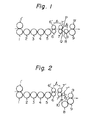
- a film is supplied between a hard chrome plated roll 1 and a rubber nip roll 1', and travels through silicone rubber-coated pre-heating rolls 2, 3, 4 and 5.
- a pair of rolls 6 and 6' define the position at which the first longitudinal drawing commences. These rolls 6 and 6' are coated with a silicone rubber.
- the - pre-heated film is subjected to a first longitudinal drawing between the pair of rolls 6 and 6' and a pair of rolls 7 and 7'.
- the roll 7 is a mirror-polished ceramic roll, with which the drawn film B-1 is brought into contact.
- the roll 7' is a silicone rubber-coated nip roll.
- the first drawing zone length (l 1 ) is the distance between the nip point between the pair of rolls 6 and 6' and the nip point between the pair of rolls 7 and 7'.
- the film B-1 longitudinally drawn in the first drawing zone is then kept in close contact with the roll 7 over the peripheral length spanning from point P on the roll 7 (i.e., the nip point between the rolls 7 and 7') to point Q on the roll 7.
- the film B-1 is again longitudinally drawn in the second drawing zone having the length ( Q 2 ) spanning from the point Q to point R at which the film is brought into contact with a chill roll 8.
- Rolls 9 and 9' are a chill roll and a rubber nip roll, respectively.
- the film longitudinally drawn in the second drawing zone is then chilled by these chill rolls 8 and 9.
- the rolls 2 through 7 are driven by a driving apparatus, not illustrated in Fig. 1.
- the chilled film is fed to a transversely drawing apparatus (not shown in Fig. 1).
- this drawing apparatus is similar to that illustrated in Fig. 1, but the second drawing zone is different from that of Fig. 1. Namely, the film is kept in contact with roll 7 over the peripheral length spanning from the nip point between the rolls 7 and 7' to the nip point of rolls 7 and 7". These three rolls 7, 7' and 7" are coated with silicone. The rolls 7' and 7" are disposed vertically and horizontally adjacent to the driving roll 7, respectively. Then, the film is longitudinally drawn in the second drawing zone having the length (Q 2 ) spanning from the nip point between the rolls 7 and 7" to an air-ejecting nozzle 10. The air-ejecting nozzle is disposed between the roll 7 and chill roll 8 so that the second drawing zone length (Q 2 ) is shorter than l 1 /2.
- this drawing apparatus has three first drawing zones which have lengths of l 11 , l 12 and l 13 , respectively.
- the total first drawing zone length (Q 1 ) in the first drawing step is the sum of these three drawing zone lengths l 11 , Z 12 and l 13 .
- Rolls-6, 6', 7, 7', 12 and 12' are coated with a silicone rubber. Of these, rolls 6, 7 and 12 are driven by a driving apparatus (not shown in Fig. 3).
- the second drawing zone length (l 2 ) spans from the point, where the film leaves a silicone rubber-coated roll 13, to the point where the film is brought into contact with a chill roll 8.
- the film travelling on the roll 13 is kept in close contact with the roll 13 over the length spanning from the nip point between the roll 13 and the nip roll 13' to the point where the film leaves the roll 13.
- an electrostatic charge depositing wire 11 is disposed in close proximity to the point where the film leaves the roll 13.
- the apparatus used for drawing the film in the longitudinal direction was similar to that illustrated in Fig. 1.
- the testing conditions were as follows.
- the longitudinally drawn films B-2 were tested for their degree of variation in thickness over the length of 3 meters by using an electromicro-thickness meter. The degree of variation was expressed by the following ratings. The test results are shown in Table I, below.
- the period of time, over which the film was kept in contact with roll 7, varied in the range of from about 0.24 to 0.36 second. This is because the point Q (illustrated in Fig. 1) was displaced although only to a minor extent depending upon the particular drawing conditions employed.
- the apparatus used for drawing the film in the longitudinal direction was similar to that illustrated in Fig. 1, but, as illustrated in Fig. 4, a displaceable chill roll 8' of a small diameter was provided between the contact roll 7 and the roll 8.
- the chill roll 8' was vertically displaced so that the period of time, over which the film was kept in contact with the roll 7, was varied without great change in the drawing zone length between the roll 7 and the roll 8'. Namely, when the chill roll 8' was upward displaced to thrust up the film, the point Q gradually moved upward like Q 1 ⁇ Q 2 ⁇ Q 3 so that the drawing tension and the adhesion of the film to the roll 7 was balanced.
- the point Q reached the nip point (Q 3 ) of the rolls 7 and 7', the contact time of the film with the roll 7 was minimum.
- the films B-2 obtained in run Nos. 2 and 4, were drawn in the transverse direction 3.7 times their original length at 120°C and then, heat-set at 230°C. Properties of the resultant films are shown in Tabel III, below.
- Chips of polyethylene terephthalate (having an intrinsic viscosity of 0.60 and containing 0.08% by weight of kaolin particles having an average particle size of 2.3 microns incorporated therein in the polymerization step) were dried at 170°C for 3 hours.
- the dried chips were melt-extruded at 285°C through a T-die of an extruder into a sheet.
- the extruded sheet was cast on a rotating drum, maintained at 30°C, to be solidified into film A having a width of 300 mm and a thickness of 200 microns.
- the film A was drawn in the longitudinal direction under the following conditions.
- the film was drawn in the transverse direction 3.6 times its original length at 110°C and then, heat-set at 220°C for 4 seconds to obtain a biaxially drawn film having a thickness of 11 microns.
- the take-up speed of the biaxially drawn film was about 90 m/min.
- the longitudinally drawn film was drawn in the transverse direction and then heat-set, in the same manner as that in the preceding item (1), thereby to obtain a biaxially drawn film having a thickness of 11 microns.
- a film A having a width of 300 mm and a thickness of 240 microns was prepared in a manner similar to that in the preceding item (1).
- the film A was drawn in the longitudinal direction under the following conditions.
- the film was drawn in the transverse direction under the same conditions as those described in the preceding item (1) and then, heat-set at 220°C to obtain a biaxially drawn film having a thickness of 11 microns.
- a film A having a thickness of 350 microns was prepared in a manner similar to that described in item (1) in EXAMPLE 3. The film A was drawn in the longitudinal direction.
- the longitudinally drawn film B-2 was drawn 3.2 times its original length in the transverse direction at 90°C, and then drawn 2.0 times its original length again in the longitudinal direction at 90°C and, finally, heat-set at 180°C to obtain a biaxially drawn and longitudially strengthened film having a thickness of 12 microns.
- the take-up speed of the film was 150 m/min.
- a film A having a thickness of 230 microns was prepared in a manner similar to that described in item (1) in EXAMPLE 3.
- the film A was drawn in the longitudinal direction.
- the above-mentioned film B-2 was drawn 3.2 times its original length in the transverse direction at 90°C, then, 2.0 times its original length again in the longitudinal direction at 90°C, and finally, heat-set at 180°C thereby to obtain a biaxially oriented film particularly strengthened in the longitudinal direction and having a thickness of 12 microns.
- the take-up speed of the film was 150 m/min.
- the film B-2 was drawn 3.2 times its original length in the transverse direction at 90°C, then 1.4 to 2.0 times its original length again in the longitudinal direction at 90°C, and finally, heat-set at 180°C thereby to obtain a biaxially oriented film particularly strengthened in the longitudinal direction and having a thickness of 12 microns.
- the take-up speed of the film was 150 m/min.
Landscapes
- Engineering & Computer Science (AREA)
- Mechanical Engineering (AREA)
- Shaping By String And By Release Of Stress In Plastics And The Like (AREA)
Applications Claiming Priority (2)
| Application Number | Priority Date | Filing Date | Title |
|---|---|---|---|
| JP132345/80 | 1980-09-25 | ||
| JP55132345A JPS6056101B2 (ja) | 1980-09-25 | 1980-09-25 | ポリエステルフイルムの製造方法 |
Publications (2)
| Publication Number | Publication Date |
|---|---|
| EP0049108A1 true EP0049108A1 (de) | 1982-04-07 |
| EP0049108B1 EP0049108B1 (de) | 1984-12-27 |
Family
ID=15079164
Family Applications (1)
| Application Number | Title | Priority Date | Filing Date |
|---|---|---|---|
| EP81304394A Expired EP0049108B1 (de) | 1980-09-25 | 1981-09-24 | Verfahren zur Herstellung von Polyesterfolien |
Country Status (4)
| Country | Link |
|---|---|
| US (1) | US4370291A (de) |
| EP (1) | EP0049108B1 (de) |
| JP (1) | JPS6056101B2 (de) |
| DE (1) | DE3167964D1 (de) |
Cited By (4)
| Publication number | Priority date | Publication date | Assignee | Title |
|---|---|---|---|---|
| EP0390191A2 (de) * | 1989-03-30 | 1990-10-03 | Diafoil Hoechst Co., Ltd | Biaxial gestreckter Polyesterfilm und Verfahren zu seiner Herstellung |
| WO1997046368A1 (de) * | 1996-05-31 | 1997-12-11 | Brückner Maschinenbau GmbH | Zumindest zweistufiges verfahren zur längsreckung von kunststoffolien sowie danach hergestellte kunststoffolie und zugehörige vorrichtung |
| US7141307B2 (en) | 2004-06-26 | 2006-11-28 | Mitsubishi Polyester Film Gmbh | Extrusion-coatable polyester film comprising poly(m-xyleneadipamide) |
| WO2010112418A1 (en) * | 2009-03-31 | 2010-10-07 | Dsm Ip Assets B.V. | Method and device for producing a polymer tape |
Families Citing this family (28)
| Publication number | Priority date | Publication date | Assignee | Title |
|---|---|---|---|---|
| US4497865A (en) * | 1982-02-17 | 1985-02-05 | Toray Industries, Inc. | Polyethylene terephthalate film, process for the production thereof and magnetic recording medium therefrom |
| JPS59140028A (ja) * | 1983-01-18 | 1984-08-11 | Diafoil Co Ltd | ポリエステルフイルムの製造方法 |
| US4610833A (en) * | 1983-09-14 | 1986-09-09 | Diafoil Company, Limited | Process for preparing biaxially stretched polyester films |
| JPS61102232A (ja) * | 1984-10-26 | 1986-05-20 | Diafoil Co Ltd | 包装用ポリエステルフィルム |
| JPH0625267B2 (ja) * | 1985-12-17 | 1994-04-06 | ダイアホイルヘキスト株式会社 | 高密度磁気記録媒体用ポリエチレン−2,6−ナフタレ−トフイルム |
| US4853602A (en) * | 1985-12-24 | 1989-08-01 | E. I. Dupont De Nemours And Company | System for using synchronous secondaries of a linear motor to biaxially draw plastic films |
| US4867937A (en) * | 1987-02-17 | 1989-09-19 | Minnesota Mining And Manufacturing Company | Process for producing high modulus film |
| BR8707774A (pt) * | 1987-06-17 | 1989-10-03 | Du Pont | Sistema para o uso de secundarias sincronicas de um motor linear na tiragem biaxial de peliculas de plastico |
| KR960007293B1 (ko) * | 1988-06-23 | 1996-05-30 | 도오레 가부시기가이샤 | 폴리에스테르 필름의 제조방법 |
| JPH02105329A (ja) * | 1988-10-13 | 1990-04-17 | Fuji Photo Film Co Ltd | 磁気テープ製造方法 |
| US5139727A (en) * | 1988-11-11 | 1992-08-18 | Daifoil Company, Limited | Process for producing biaxially oriented polyester film |
| US5076977A (en) * | 1990-01-10 | 1991-12-31 | Eastman Kodak Company | Process for controlling curl in polyester film |
| JPH0578983U (ja) * | 1991-08-20 | 1993-10-26 | 株式会社日本礦油 | 圧力排出容器 |
| US5385704A (en) * | 1993-07-27 | 1995-01-31 | Eastman Kodak Company | Process of making polyethylene terephthalate photographic film base |
| DE19508597A1 (de) * | 1995-03-10 | 1996-09-12 | Hoechst Ag | Verfahren zum Herstellen biaxial verstreckter Folien sowie Vorrichtung zur Durchführung des Verfahrens |
| US6179939B1 (en) | 1997-05-12 | 2001-01-30 | Kimberly-Clark Worldwide, Inc. | Methods of making stretched filled microporous films |
| US6342292B1 (en) * | 1997-12-16 | 2002-01-29 | Asahi Kasei Kabushiki Kaisha | Organic thin film and process for producing the same |
| US6358457B1 (en) | 1998-11-13 | 2002-03-19 | 3M Innovative Properties Company | Method of stretching films according to an overbias or overstretch profile |
| US6303067B1 (en) | 1998-11-13 | 2001-10-16 | 3M Innovative Properties Company | Method of stretching films according to an overbias or overstretch stretch profile |
| DE10022939A1 (de) * | 2000-05-11 | 2001-11-15 | Hans Kaesbauer | Verfahren und Vorrichtung zum Auftragen einer Lackschicht auf die Oberseite eines Druckmediums |
| US20060183832A1 (en) * | 2001-06-13 | 2006-08-17 | Masaaki Tsuchihashi | Plasticizer for polyester resin |
| WO2003093008A1 (fr) * | 2002-05-02 | 2003-11-13 | Teijin Dupont Films Japan Limited | Film lamelle a usage optique |
| US6965474B2 (en) * | 2003-02-12 | 2005-11-15 | 3M Innovative Properties Company | Polymeric optical film |
| US7132065B2 (en) * | 2003-02-12 | 2006-11-07 | 3M Innovative Properties Company | Process for manufacturing polymeric optical film |
| US7405784B2 (en) * | 2003-02-12 | 2008-07-29 | 3M Innovative Properties Company | Compensators for liquid crystal displays with biaxially stretched single film with crystallization modifier |
| CN104170098B (zh) * | 2012-03-14 | 2017-03-01 | 东洋纺株式会社 | 太阳能电池背面密封片材及太阳能电池组件 |
| CN104149368A (zh) * | 2014-07-28 | 2014-11-19 | 浙江绍兴华东包装有限公司 | 一种单双点可切换式bopet薄膜加工装置及方法 |
| CN106808676A (zh) * | 2015-11-27 | 2017-06-09 | 朱晓鹏 | 一种强力隔离膜制作工艺及一种强力隔离膜 |
Citations (8)
| Publication number | Priority date | Publication date | Assignee | Title |
|---|---|---|---|---|
| US2823421A (en) * | 1952-05-12 | 1958-02-18 | Du Pont | Stretching of polyethylene terephthalate film |
| US2884663A (en) * | 1956-12-20 | 1959-05-05 | Du Pont | Process for producing improved polymeric terephthalate film |
| US3088173A (en) * | 1961-06-02 | 1963-05-07 | Du Pont | Process for preparing oriented polymeric linear terephthalate film with a deglossed writeable surface |
| DE1629466B1 (de) * | 1965-03-05 | 1972-05-25 | Ici Ltd | Verfahren zum herstellen biaxial gereckter filme hoher festigkeit aus polyaethylenterepthalat |
| US3734994A (en) * | 1971-02-09 | 1973-05-22 | Du Pont | Two-stage uniaxial orientation of polyethylene terephthalate films |
| FR2171896A1 (de) * | 1972-01-27 | 1973-09-28 | Asahi Chemical Ind | |
| DE2320118A1 (de) * | 1973-04-17 | 1974-11-07 | Teijin Ltd | Verfahren zur herstellung einer biaxial orientierten polyesterfolie |
| JPS548672A (en) * | 1977-06-21 | 1979-01-23 | Toray Ind Inc | Production of polyester film |
Family Cites Families (8)
| Publication number | Priority date | Publication date | Assignee | Title |
|---|---|---|---|---|
| BE625064A (de) * | 1961-11-21 | |||
| JPS4918628B1 (de) * | 1970-10-26 | 1974-05-11 | ||
| JPS4944084A (de) * | 1972-09-04 | 1974-04-25 | ||
| JPS5748377B2 (de) * | 1974-03-14 | 1982-10-15 | ||
| JPS5749377B2 (de) * | 1974-04-17 | 1982-10-21 | ||
| NL7609725A (nl) * | 1975-09-06 | 1977-03-08 | Hoechst Ag | Alkoxyderivaten van aan de n gesubstitueerde cyclische aminen en werkwijze voor hun be- reiding. |
| JPS6025255B2 (ja) * | 1977-04-11 | 1985-06-17 | 帝人株式会社 | ポリエステルフイルム |
| JPS5456674A (en) * | 1977-10-12 | 1979-05-07 | Daiafoil | Method of making polyester film |
-
1980
- 1980-09-25 JP JP55132345A patent/JPS6056101B2/ja not_active Expired
-
1981
- 1981-09-21 US US06/304,200 patent/US4370291A/en not_active Expired - Lifetime
- 1981-09-24 DE DE8181304394T patent/DE3167964D1/de not_active Expired
- 1981-09-24 EP EP81304394A patent/EP0049108B1/de not_active Expired
Patent Citations (8)
| Publication number | Priority date | Publication date | Assignee | Title |
|---|---|---|---|---|
| US2823421A (en) * | 1952-05-12 | 1958-02-18 | Du Pont | Stretching of polyethylene terephthalate film |
| US2884663A (en) * | 1956-12-20 | 1959-05-05 | Du Pont | Process for producing improved polymeric terephthalate film |
| US3088173A (en) * | 1961-06-02 | 1963-05-07 | Du Pont | Process for preparing oriented polymeric linear terephthalate film with a deglossed writeable surface |
| DE1629466B1 (de) * | 1965-03-05 | 1972-05-25 | Ici Ltd | Verfahren zum herstellen biaxial gereckter filme hoher festigkeit aus polyaethylenterepthalat |
| US3734994A (en) * | 1971-02-09 | 1973-05-22 | Du Pont | Two-stage uniaxial orientation of polyethylene terephthalate films |
| FR2171896A1 (de) * | 1972-01-27 | 1973-09-28 | Asahi Chemical Ind | |
| DE2320118A1 (de) * | 1973-04-17 | 1974-11-07 | Teijin Ltd | Verfahren zur herstellung einer biaxial orientierten polyesterfolie |
| JPS548672A (en) * | 1977-06-21 | 1979-01-23 | Toray Ind Inc | Production of polyester film |
Non-Patent Citations (1)
| Title |
|---|
| PATENTS ABSTRACTS OF JAPAN Vol. 3, No. 32, 17 March 1979, page 131, C40; & JP-A-54 008 672 * |
Cited By (5)
| Publication number | Priority date | Publication date | Assignee | Title |
|---|---|---|---|---|
| EP0390191A2 (de) * | 1989-03-30 | 1990-10-03 | Diafoil Hoechst Co., Ltd | Biaxial gestreckter Polyesterfilm und Verfahren zu seiner Herstellung |
| EP0390191A3 (de) * | 1989-03-30 | 1991-03-20 | Diafoil Hoechst Co., Ltd | Biaxial gestreckter Polyesterfilm und Verfahren zu seiner Herstellung |
| WO1997046368A1 (de) * | 1996-05-31 | 1997-12-11 | Brückner Maschinenbau GmbH | Zumindest zweistufiges verfahren zur längsreckung von kunststoffolien sowie danach hergestellte kunststoffolie und zugehörige vorrichtung |
| US7141307B2 (en) | 2004-06-26 | 2006-11-28 | Mitsubishi Polyester Film Gmbh | Extrusion-coatable polyester film comprising poly(m-xyleneadipamide) |
| WO2010112418A1 (en) * | 2009-03-31 | 2010-10-07 | Dsm Ip Assets B.V. | Method and device for producing a polymer tape |
Also Published As
| Publication number | Publication date |
|---|---|
| DE3167964D1 (en) | 1985-02-07 |
| US4370291A (en) | 1983-01-25 |
| JPS6056101B2 (ja) | 1985-12-09 |
| JPS5757631A (en) | 1982-04-06 |
| EP0049108B1 (de) | 1984-12-27 |
Similar Documents
| Publication | Publication Date | Title |
|---|---|---|
| EP0049108B1 (de) | Verfahren zur Herstellung von Polyesterfolien | |
| EP1038653B1 (de) | Verfahren zur Herstellung einer biaxial gestreckten Polyesterfolie | |
| EP1185411B1 (de) | Polyethylenterephthalatfolie höher festigkeit und verfahren zu deren herstellung | |
| DE69916567T2 (de) | Verfahren zur Herstellung von biaxial gerecktem Polyesterfilm | |
| EP0026566B1 (de) | Verfahren zum Querstrecken von Polyäthylenterephthalat-Folie | |
| US4268464A (en) | Electrostatic pinning of extruded polyamide film | |
| US5575968A (en) | Process for the preparation of thermoplastic resin film | |
| KR20050086817A (ko) | 폴리부틸렌 테레프탈레이트 필름의 제조 방법 | |
| EP0390191B1 (de) | Biaxial gestreckter Polyesterfilm und Verfahren zu seiner Herstellung | |
| US5833904A (en) | Process for the production of biaxially stretched films and apparatus for carrying out the process | |
| JP2513669B2 (ja) | 引裂直線性のある二軸延伸ポリエステルフイルム | |
| KR0140299B1 (ko) | 이축 배향 폴리에스테르 필름의 제조방법 | |
| JP2569471B2 (ja) | 強力化ポリエステルフイルムの製造方法 | |
| KR0157090B1 (ko) | 이축 배향 폴리에스테르 필름 및 이의 제조방법 | |
| JP2661403B2 (ja) | 二軸配向熱可塑性樹脂フィルム | |
| KR960006779B1 (ko) | 2축 배향 폴리에스테르 필름의 제조 방법 | |
| JPH02127022A (ja) | ひねり包装用フィルムの製造方法 | |
| JPH10315320A (ja) | 二軸延伸ポリエステルフィルムの製造方法 | |
| GB2091631A (en) | Base film for magnetic recording tape | |
| KR0173732B1 (ko) | 이축 배향 폴리에스테르 필름의 제조방법 | |
| KR0142039B1 (ko) | 이축 배향 폴리에스테르 필름의 제조방법 | |
| JPS58185226A (ja) | 熱可塑性フイルムの製造方法 | |
| KR960007294B1 (ko) | 폴리에틸렌 나프탈레이트 필름의 제조방법 | |
| JPH09295344A (ja) | 熱可塑性樹脂フィルムの製造方法 | |
| EP0008825B1 (de) | Herstellung von Polyamid-Folien |
Legal Events
| Date | Code | Title | Description |
|---|---|---|---|
| PUAI | Public reference made under article 153(3) epc to a published international application that has entered the european phase |
Free format text: ORIGINAL CODE: 0009012 |
|
| AK | Designated contracting states |
Designated state(s): DE FR GB LU NL |
|
| 17P | Request for examination filed |
Effective date: 19820622 |
|
| GRAA | (expected) grant |
Free format text: ORIGINAL CODE: 0009210 |
|
| AK | Designated contracting states |
Designated state(s): DE FR GB LU NL |
|
| REF | Corresponds to: |
Ref document number: 3167964 Country of ref document: DE Date of ref document: 19850207 |
|
| ET | Fr: translation filed | ||
| PG25 | Lapsed in a contracting state [announced via postgrant information from national office to epo] |
Ref country code: LU Free format text: LAPSE BECAUSE OF NON-PAYMENT OF DUE FEES Effective date: 19850930 |
|
| PLBE | No opposition filed within time limit |
Free format text: ORIGINAL CODE: 0009261 |
|
| STAA | Information on the status of an ep patent application or granted ep patent |
Free format text: STATUS: NO OPPOSITION FILED WITHIN TIME LIMIT |
|
| 26N | No opposition filed | ||
| PGFP | Annual fee paid to national office [announced via postgrant information from national office to epo] |
Ref country code: FR Payment date: 20000912 Year of fee payment: 20 |
|
| PGFP | Annual fee paid to national office [announced via postgrant information from national office to epo] |
Ref country code: DE Payment date: 20000918 Year of fee payment: 20 |
|
| PGFP | Annual fee paid to national office [announced via postgrant information from national office to epo] |
Ref country code: GB Payment date: 20000920 Year of fee payment: 20 |
|
| PGFP | Annual fee paid to national office [announced via postgrant information from national office to epo] |
Ref country code: NL Payment date: 20000928 Year of fee payment: 20 |
|
| PG25 | Lapsed in a contracting state [announced via postgrant information from national office to epo] |
Ref country code: GB Free format text: LAPSE BECAUSE OF EXPIRATION OF PROTECTION Effective date: 20010923 |
|
| PG25 | Lapsed in a contracting state [announced via postgrant information from national office to epo] |
Ref country code: NL Free format text: LAPSE BECAUSE OF EXPIRATION OF PROTECTION Effective date: 20010924 |
|
| REG | Reference to a national code |
Ref country code: GB Ref legal event code: PE20 Effective date: 20010923 |
|
| NLV7 | Nl: ceased due to reaching the maximum lifetime of a patent |
Effective date: 20010924 |