EP0048658B1 - Verfahren zum Einführen eines Endlosfadens in eine Schneidmaschine - Google Patents
Verfahren zum Einführen eines Endlosfadens in eine Schneidmaschine Download PDFInfo
- Publication number
- EP0048658B1 EP0048658B1 EP81401406A EP81401406A EP0048658B1 EP 0048658 B1 EP0048658 B1 EP 0048658B1 EP 81401406 A EP81401406 A EP 81401406A EP 81401406 A EP81401406 A EP 81401406A EP 0048658 B1 EP0048658 B1 EP 0048658B1
- Authority
- EP
- European Patent Office
- Prior art keywords
- cylinder
- thread
- blade
- cutting
- wire
- Prior art date
- Legal status (The legal status is an assumption and is not a legal conclusion. Google has not performed a legal analysis and makes no representation as to the accuracy of the status listed.)
- Expired
Links
Images


Classifications
-
- D—TEXTILES; PAPER
- D01—NATURAL OR MAN-MADE THREADS OR FIBRES; SPINNING
- D01G—PRELIMINARY TREATMENT OF FIBRES, e.g. FOR SPINNING
- D01G1/00—Severing continuous filaments or long fibres, e.g. stapling
- D01G1/02—Severing continuous filaments or long fibres, e.g. stapling to form staple fibres not delivered in strand form
- D01G1/04—Severing continuous filaments or long fibres, e.g. stapling to form staple fibres not delivered in strand form by cutting
-
- Y—GENERAL TAGGING OF NEW TECHNOLOGICAL DEVELOPMENTS; GENERAL TAGGING OF CROSS-SECTIONAL TECHNOLOGIES SPANNING OVER SEVERAL SECTIONS OF THE IPC; TECHNICAL SUBJECTS COVERED BY FORMER USPC CROSS-REFERENCE ART COLLECTIONS [XRACs] AND DIGESTS
- Y10—TECHNICAL SUBJECTS COVERED BY FORMER USPC
- Y10S—TECHNICAL SUBJECTS COVERED BY FORMER USPC CROSS-REFERENCE ART COLLECTIONS [XRACs] AND DIGESTS
- Y10S83/00—Cutting
- Y10S83/913—Filament to staple fiber cutting
-
- Y—GENERAL TAGGING OF NEW TECHNOLOGICAL DEVELOPMENTS; GENERAL TAGGING OF CROSS-SECTIONAL TECHNOLOGIES SPANNING OVER SEVERAL SECTIONS OF THE IPC; TECHNICAL SUBJECTS COVERED BY FORMER USPC CROSS-REFERENCE ART COLLECTIONS [XRACs] AND DIGESTS
- Y10—TECHNICAL SUBJECTS COVERED BY FORMER USPC
- Y10T—TECHNICAL SUBJECTS COVERED BY FORMER US CLASSIFICATION
- Y10T83/00—Cutting
- Y10T83/04—Processes
- Y10T83/0515—During movement of work past flying cutter
-
- Y—GENERAL TAGGING OF NEW TECHNOLOGICAL DEVELOPMENTS; GENERAL TAGGING OF CROSS-SECTIONAL TECHNOLOGIES SPANNING OVER SEVERAL SECTIONS OF THE IPC; TECHNICAL SUBJECTS COVERED BY FORMER USPC CROSS-REFERENCE ART COLLECTIONS [XRACs] AND DIGESTS
- Y10—TECHNICAL SUBJECTS COVERED BY FORMER USPC
- Y10T—TECHNICAL SUBJECTS COVERED BY FORMER US CLASSIFICATION
- Y10T83/00—Cutting
- Y10T83/465—Cutting motion of tool has component in direction of moving work
- Y10T83/4766—Orbital motion of cutting blade
- Y10T83/4795—Rotary tool
- Y10T83/483—With cooperating rotary cutter or backup
- Y10T83/4838—With anvil backup
- Y10T83/4841—With resilient anvil surface
-
- Y—GENERAL TAGGING OF NEW TECHNOLOGICAL DEVELOPMENTS; GENERAL TAGGING OF CROSS-SECTIONAL TECHNOLOGIES SPANNING OVER SEVERAL SECTIONS OF THE IPC; TECHNICAL SUBJECTS COVERED BY FORMER USPC CROSS-REFERENCE ART COLLECTIONS [XRACs] AND DIGESTS
- Y10—TECHNICAL SUBJECTS COVERED BY FORMER USPC
- Y10T—TECHNICAL SUBJECTS COVERED BY FORMER US CLASSIFICATION
- Y10T83/00—Cutting
- Y10T83/647—With means to convey work relative to tool station
- Y10T83/6572—With additional mans to engage work and orient it relative to tool station
Definitions
- the present invention relates to the manufacture of wires cut from thermoplastic material, in particular glass wires, and it relates more particularly to a method and a device for feeding a continuous glass wire into a cutting device.
- the cutting of wires is obtained by passing the filamentary material between a support cylinder or anvil and a cutting cylinder equipped with blades regularly arranged at its periphery.
- the cutter is arranged to come into contact under pressure with the circumferential surface of the support cylinder, thus defining a cutting area.
- the cutting device is most often supplied by glass strands drawn directly from a certain number of dies.
- the cutting machine comprises a support cylinder extended by a truncated cone ending in a vertex of small diameter.
- a starter roller made up of a series of discs, has just pressed on a generator of the truncated cone.
- the cutter / anvil assembly rotates continuously at its normal speed.
- the wire first passing through a guide wheel aligned with the cutting zone, is brought in the vicinity of the top of the truncated cone on which it therefore winds at low speed. Because the wire tends to follow a rectilinear trajectory, it is quickly wedged between the starter roller and the surface of the truncated cone, gradually rises on it by undergoing an increasing drawing speed to be finally taken up between the anvil and cutter.
- Another type of device described in French publication FR-A-2 397 370, also provides for lateral introduction of the wire into the cutting apparatus.
- This device comprises an auxiliary support cylinder disposed adjacent to one end of the main support cylinder and axially aligned with the latter, and an auxiliary blade cylinder arranged so as to cooperate with the auxiliary support cylinder.
- the wire is introduced between the auxiliary cylinders at low speed, and held in this position by a grooved pulley.
- the speed of the two auxiliary cylinders, which act as the cutting machine, is gradually increased until the wire reaches its normal drawing speed. By moving the grooved pulley, the wire is then brought into the main cutting area.
- This device constitutes an interesting solution to the difficulties linked to the introduction of a wire into a cutting machine rotating at high speed.
- it is necessary to dismantle and reassemble the auxiliary cylinders which is not without presenting some drawback in a continuous production which requires the minimum of idle time. .
- One of the aims of the present invention is to provide a simple method for introducing a wire. continuous in a cutting machine, and which avoids the drawbacks described above.
- the method according to the invention consists essentially in stretching the wire in an area between the planes passing through the sides of the blade-holder cylinder cooperating with an anvil cylinder, the axes of rotation of said cylinders passing in a substantially horizontal plane, then in deflecting the wire thus stretched towards the cutting zone defined by the contact zone between the anvil cylinder and the blade-holder cylinder, to lay it on at least a portion of the surface of the cylinder arranged upstream; said surface portion being substantially adjacent to the cutting zone.
- the method of relaunching a wire in a cutting machine comprising an anvil cylinder and a blade holder cylinder is implemented in accordance with the schematic representations given in FIGS. 1 A and 1 B.
- a wire 15a coming from a die disposed upstream of the cutting machine, is firstly drawn along the path shown in dotted lines by a drawing device called launcher arranged downstream of said machine.
- the launcher is arranged so that the wire is stretched in an area between the planes passing through the sides of the blade cylinder 19. Furthermore, the path of the wire 15a is such that during this drawing operation the wire remains free from any contact with said cylinders.
- Fig. 1'8 represents a variant of the process according to the invention.
- the wire 15a deflected by a pulley 17, is partially wound on the upstream cylinder (anvil 20) before following the dotted path imposed by the launcher. There again the wire is drawn in an area between the planes passing through the sides of the blade cylinder 19.
- a force F is then exerted on the wire 15a so as to apply it only to the surface portion of the upstream cylinder adjacent to the cutting zone.
- the wire then follows the path in full line and is maintained in this position until it is entrained in the cutting zone.
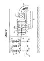
- FIG. 1A The process illustrated schematically in FIG. 1A can be used in a production line as shown in FIG. 2 comprising a series of dies, designated by the reference 10 which deliver several glass strands, an assembly 11 housing a cutting machine and downstream of the chain a device 12 for drawing said glass strands.
- the dies 10 are supplied from molten glass or glass beads delivered by a supply device not shown. These channels, generally in rhodium-plated platinum, are heated by the Joule effect; they are provided at their lower part with a plurality of orifices from which a plurality of filaments 13 can be drawn: mechanically. These filaments 13 are in the form of sheets and are coated with a lubricating sizing product, commonly called sizing, by passing over a coating device 14. They are then joined together in the form of wires 15 by assembly rollers 16.
- the wires 15 thus formed are brought after passing over the pulleys 17 to a guide device 18, for example a comb, before being introduced into the cutting machine composed of a blade-holding drum 19 and a support drum 20, the axes of rotation of which pass through a horizontal plane.
- a guide device 18 for example a comb
- the assembly 11 housing the cutting machine comprises a frame 21 supporting a device 22 for introducing the wire into the cutting zone; this device 22 is placed above the cutting machine consisting of a blade-holding drum 19 and a support drum 20 and surrounded by a cover shown diagrammatically at 23. The whole rests on a floor referenced 24.
- a device for receiving and transferring the cut fibers is symbolized at 25.
- a launcher 12 Downstream is shown a launcher 12, shown diagrammatically by two cylinders 26 and 27 cooperating to stretch a wire 15a, emanating from one of the dies 10, wire then recovered in a chute 28.
- the launch can also be ensured by
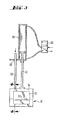
- Figs. 3 and 4 respectively show front and sectional views of the device 22 for introducing the wire into the cutting zone.
- This device essentially comprises a jack 30, the rod 41 of which is provided at its end with a pusher assembly 31 and on which is fixed very rigidly a hollow rod 32 parallel to the rod of the jack 30.
- This rod 32 passes through a hole or eye 33 formed in a plate extending outwardly from the base of the jack 30.
- the purpose of this rod is in particular to precisely preserve the orientation of the pusher by preventing the rod of the jack from turning on itself when the said jack is put into service.
- the pusher itself consists of a rigid piece 34, preferably metallic, and a part 35, made of a flexible material, partially embedded in the previous one.
- the part 34 has at its lower part a thinning which makes it possible to deeply penetrate the wire between the anvil and the blade holder at the time of its recovery.
- One of the large sections of the part 34 comprises a housing having a vertical face and a face inclined along the slope imparted by the thinning of the part to its lower part.
- Part 35 consists of a plate closely fitting the housing described above.
- the upper part of the plate corresponding to the vertical face of the housing is tightly fixed to the latter (by gluing, for example).
- the lower part corresponding to the inclined face of the housing is free relative to the latter.
- the upper and lower parts of the plate 35 are delimited by a horizontal groove 36 deeply cutting the external face of said plate over its entire width.
- the width of the plate 35 is substantially equal to the width of the active cutting zone defined by the length of the cutting blades.
- Fig. 4 which represents a partial section of the pusher 31, shows its internal structure.
- the hollow rod 32 is connected directly to an internal conduit 37 which connects it to a tubular chamber 38; this chamber 38 extends horizontally over a distance substantially equal to the width of the plate 35.
- the chamber 38 communicates with the outside by a slot 39 (or by a series of conduits) which opens facing the lower part of plate 35.
- the wire introduction device referenced 22 in FIG. 2 and as illustrated in FIGS. 3 and 4, is activated.
- the displacement of the pusher is triggered automatically as soon as the launcher reaches the chosen drawing speed.
- the pusher 31 In its rectilinear movement, the pusher 31 meets the wire 15a, gradually drives it and at the end of the stroke, introduces it deeply between the blade-holder cylinder 19 and the anvil cylinder 20 (fig. 4). This action has the effect of bringing the fit 15a into contact with a portion of the surface of the blade holder and the anvil, said portions being adjacent to the cutting zone.
- the pusher 31 returns to its rest position and the downstream end of the wire 15a is discharged by the launcher 12.
- the lower end of the pusher is applied to the surface of the blade cylinder.
- the device described above is particularly suitable when the surface of the cylinder arranged upstream is discontinuous. This is the case, for example, of the blade-holder cylinders, the structure of which is such that the cutting edge of the blades only protrudes into the cutting zone.
- These cylinders mounted upstream are generally powered and simultaneously assume the drawing of the wires and the drive of the anvil by cooperation of the surfaces in contact in the cutting zone.
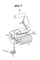
- FIG. 5 illustrating the method of introducing the wire according to FIG. 1 B.
- the device 50 comprises an arm 51 pivoting about an axis 52 and provided at its free end with a roller 53 mounted idly on its axis, parallel ment to the axes of rotation of the anvil 20 and the blade holder 19.
- the arm 51 is set back from the cutting machine and the roller 53 has a length sufficient to apply over the entire width of the cylinder 20. For for clarity of the figure, only one wire is shown.
- the die is restarted as described above, but the wire 15a drawn by the launcher is then partially wound on the surface of the anvil 20 in rotation after passing over a pulley 17, the device 50 being in the rest position shown in dotted lines.
- the device 50 is actuated and takes the position shown in solid lines. In this position the roller 53 rests on the surface of the anvil and presses the wire 15a on the surface portion adjacent to the cutting zone, which causes the wire to be drawn into the cutting zone.
- the method according to the invention and the implementation devices described above apply to the continuous manufacture of cut fibers obtained either from yarns from several dies, or from yarn (s) from (s) only one sector.
- the cutting machine is no longer supplied with power, and it is possible to envisage reducing its speed of rotation, or even stopping it.
- the recovery process can be simplified since it is no longer necessary to use the launcher.
- the operator manually stretches the wire downstream of the cutting machine, which it starts to rotate slowly, then activates the control of the wire introduction device.
- the method and its implementation according to the invention makes it possible to relaunch a wire very quickly and safely; in fact, the automatic introduction of the wire into the cutting zone eliminates any risk for the operator responsible for restarting the wire.
- the device for implementing the method is entirely independent of the cutting machine. As a result, it can be used on any cutting machine. In addition, it does not in any way interfere with the disassembly and reassembly of a cutting machine, which is particularly appreciable in the context of continuous production where stops must be reduced to a minimum.
Landscapes
- Engineering & Computer Science (AREA)
- Textile Engineering (AREA)
- Wire Processing (AREA)
- Yarns And Mechanical Finishing Of Yarns Or Ropes (AREA)
Claims (12)
Applications Claiming Priority (2)
| Application Number | Priority Date | Filing Date | Title |
|---|---|---|---|
| FR8019704 | 1980-09-12 | ||
| FR8019704A FR2490251A1 (fr) | 1980-09-12 | 1980-09-12 | Procede et dispositif d'introduction d'un fil continu dans une machine de coupe |
Publications (2)
| Publication Number | Publication Date |
|---|---|
| EP0048658A1 EP0048658A1 (de) | 1982-03-31 |
| EP0048658B1 true EP0048658B1 (de) | 1984-05-16 |
Family
ID=9245872
Family Applications (1)
| Application Number | Title | Priority Date | Filing Date |
|---|---|---|---|
| EP81401406A Expired EP0048658B1 (de) | 1980-09-12 | 1981-09-10 | Verfahren zum Einführen eines Endlosfadens in eine Schneidmaschine |
Country Status (4)
| Country | Link |
|---|---|
| US (1) | US4411180A (de) |
| EP (1) | EP0048658B1 (de) |
| DE (1) | DE3163649D1 (de) |
| FR (1) | FR2490251A1 (de) |
Families Citing this family (16)
| Publication number | Priority date | Publication date | Assignee | Title |
|---|---|---|---|---|
| US4551160A (en) * | 1984-10-22 | 1985-11-05 | Owens-Corning Fiberglas Corporation | Method and apparatus for forming glass filaments |
| SE502070C2 (sv) * | 1993-11-19 | 1995-07-31 | Aplicator System Ab | Anordning för repetitiv utmatning av fiberknippen med spridd fiberriktning från en magasinsrulle med fibertråd |
| US6148640A (en) * | 1998-08-03 | 2000-11-21 | Johns Manvill International, Inc. | Method for making chopped fiber |
| FR2804974B1 (fr) * | 2000-02-16 | 2002-06-28 | Vetrotex France Sa | Systeme destine a la fabrication de fils coupes en matiere thermoplastique |
| FR2858973B1 (fr) * | 2003-08-20 | 2007-06-08 | Saint Gobain Vetrotex | Procede de coupe directe sous filiere et dispositif pour sa mise en oeuvre |
| FR2872154B1 (fr) * | 2004-06-28 | 2006-08-04 | Saint Gobain Vetrotex | Installation de prise automatique de fils |
| US7363842B1 (en) * | 2004-08-17 | 2008-04-29 | Johns Manville | Fiber chopper |
| US7424842B1 (en) * | 2004-08-17 | 2008-09-16 | Johns Nanville | Fiber chopper |
| FR2876392B1 (fr) | 2004-10-07 | 2006-12-15 | Saint Gobain Vetrotex | Systeme destine a la fabrication de fils coupes |
| FR2888838B1 (fr) | 2005-07-22 | 2007-10-05 | Saint Gobain Vetrotex | Installation de prise automatique de fils |
| US20070044607A1 (en) * | 2005-08-30 | 2007-03-01 | Bascom Randall C | Fiber chopper with improved idler roll |
| FR2916003B1 (fr) * | 2007-05-11 | 2009-08-21 | Saint Gobain Vetrotex | Systeme destine a la fabrication de fils coupes en matiere thermoplastique. |
| EP2642009A1 (de) * | 2012-03-22 | 2013-09-25 | Dietze&Schell Maschinenfabrik GmbH&Co. Kg | Vorrichtung zur Herstellung von geschnittenen Glasfasern |
| US20180354839A1 (en) | 2015-12-02 | 2018-12-13 | Ocv Intellectual Capital, Llc | Chopper assembly and method for manufacturing chopped fibers |
| WO2017127254A1 (en) | 2016-01-19 | 2017-07-27 | OCV Intellectual Capital , LLC | Chopper assembly for and method of manufacturing chopped fibers |
| CN108866680A (zh) * | 2018-07-10 | 2018-11-23 | 张家港市利佳纺织有限公司 | 一种可定长计量型切纱装置 |
Family Cites Families (6)
| Publication number | Priority date | Publication date | Assignee | Title |
|---|---|---|---|---|
| GB960955A (en) * | 1962-09-10 | 1964-06-17 | Fmc Corp | Method of producing staple fibres |
| US3285721A (en) * | 1962-11-09 | 1966-11-15 | Owens Corning Fiberglass Corp | Method and apparatus for producing strand package |
| US3485120A (en) * | 1966-09-08 | 1969-12-23 | Eastman Kodak Co | Method and apparatus for cutting elongated material |
| US3731575A (en) * | 1971-11-08 | 1973-05-08 | Owens Corning Fiberglass Corp | Chopper for linear material |
| US3815461A (en) * | 1972-10-26 | 1974-06-11 | Johns Manville | Apparatus for chopping strand |
| US4344786A (en) * | 1981-01-02 | 1982-08-17 | Owens-Corning Fiberglas Corporation | Method and apparatus for gathering strand material |
-
1980
- 1980-09-12 FR FR8019704A patent/FR2490251A1/fr active Granted
-
1981
- 1981-09-08 US US06/299,930 patent/US4411180A/en not_active Expired - Lifetime
- 1981-09-10 DE DE8181401406T patent/DE3163649D1/de not_active Expired
- 1981-09-10 EP EP81401406A patent/EP0048658B1/de not_active Expired
Also Published As
| Publication number | Publication date |
|---|---|
| EP0048658A1 (de) | 1982-03-31 |
| US4411180A (en) | 1983-10-25 |
| DE3163649D1 (en) | 1984-06-20 |
| FR2490251B1 (de) | 1982-10-08 |
| FR2490251A1 (fr) | 1982-03-19 |
Similar Documents
| Publication | Publication Date | Title |
|---|---|---|
| EP0048658B1 (de) | Verfahren zum Einführen eines Endlosfadens in eine Schneidmaschine | |
| EP0040145B1 (de) | Vorrichtung zum Schneiden langer Fasern, insbesondere von Glasfasern | |
| FR2660642A1 (fr) | Dispositif pour enrouler un materiau mince, notamment des sacs en film plastique relies ensemble en un ruban. | |
| CA1307668C (fr) | Dispositif et procede pour bobiner simultanement plusieurs fils separes sur un support en rotation | |
| EP0005664A1 (de) | Verfahren zum Führen eines faserförmigen Materials von einer Aufwickelspindel zur anderen sowie Vorrichtung zur Durchführung des Verfahrens | |
| CH647935A5 (fr) | Procede pour la production d'un materiau de remplissage, machine pour sa mise en oeuvre, application du procede et installation pour la production d'un boudin de filtres de cigarettes. | |
| EP0505275A1 (de) | Verfahren und Vorrichtung zur Herstellung eines Verbundgarnes | |
| EP1297204B1 (de) | Vorrichtung und verfahren zum schneiden von filamentlunten aus thermoplastischen material | |
| FR2632662A1 (fr) | Dispositif pour former des bobines utilisees comme bobines d'alimentation pour un retordage | |
| EP1369222A1 (de) | Verfahren zum selektiven Einbringen von Fäden in textilen multidimensionalen Vorformlingen und Vorrichtung zur Durchführung des Verfahrens | |
| CH659488A5 (fr) | Procede et dispositif pour produire des fils guipes. | |
| BE1006222A3 (fr) | Dispositif de fabrication d'un feutre de fibres. | |
| FR2466531A1 (fr) | Broche de filage ou de retordage a double torsion a d ispositif d'enfilage pneumatique | |
| EP1339902B1 (de) | Verfahren und vorrichtung zur herstellung von bauschigem glasfaserstrang | |
| BE1007920A5 (fr) | Systeme d'insertion de trame pour metier a jet de fluide. | |
| FR2630460A1 (fr) | Procede et dispositif pour former des bobines sur lesquelles deux composants d'un fil sont enroules d'une maniere etalee | |
| EP0208684B1 (de) | Verfahren und vorrichtung zum thermischen behandeln eines dünnen garnes | |
| EP1547953B1 (de) | Aufnahme- und Vereinzelvorrichtung für aus einer Bearbeitungsmaschine zugeführte Fäden | |
| EP0286769A1 (de) | Verfahren und Vorrichtung für den automatischen Kannenwechsel, bestimmt zur Aufnahme der von den Textilmaschinen kommenden Faserbänder | |
| EP0104292B1 (de) | Verfahren und Vorrichtung zum Abgeben von thermo-schrumpfbaren Kappen, die auf sich bewegende Behälter fallen | |
| EP0651078B1 (de) | Verfahren zum Zentrifugalspinnen | |
| EP0410906A1 (de) | Maschine zur Herstellung und Verarbeitung von Fäden, mit einem Behandlungsorgan, das zwischen zwei Fadentransporteinrichtungen liegt und Verfahren zur automatischen Einführung von Fäden in das Innere dieser Elemente während des Wiederanspinnens | |
| BE473746A (fr) | Perfectionnements a la fabrication de feutres, notamment en fibres de verre ou autres fibres minerales | |
| FR2982792A1 (fr) | Tete de depose d'un ruban de fibres impregnees, et dispositif de placement d'un tel ruban | |
| FR2539961A1 (fr) | Procede et dispositif de capage en continu d'un boudin de tabac |
Legal Events
| Date | Code | Title | Description |
|---|---|---|---|
| PUAI | Public reference made under article 153(3) epc to a published international application that has entered the european phase |
Free format text: ORIGINAL CODE: 0009012 |
|
| AK | Designated contracting states |
Designated state(s): BE DE FR GB IT NL SE |
|
| 17P | Request for examination filed |
Effective date: 19820915 |
|
| ITF | It: translation for a ep patent filed |
Owner name: DR. ING. A. RACHELI & C. |
|
| GRAA | (expected) grant |
Free format text: ORIGINAL CODE: 0009210 |
|
| AK | Designated contracting states |
Designated state(s): BE DE FR GB IT NL SE |
|
| REF | Corresponds to: |
Ref document number: 3163649 Country of ref document: DE Date of ref document: 19840620 |
|
| PLBE | No opposition filed within time limit |
Free format text: ORIGINAL CODE: 0009261 |
|
| STAA | Information on the status of an ep patent application or granted ep patent |
Free format text: STATUS: NO OPPOSITION FILED WITHIN TIME LIMIT |
|
| 26N | No opposition filed | ||
| ITTA | It: last paid annual fee | ||
| EAL | Se: european patent in force in sweden |
Ref document number: 81401406.4 |
|
| PGFP | Annual fee paid to national office [announced via postgrant information from national office to epo] |
Ref country code: GB Payment date: 20000811 Year of fee payment: 20 |
|
| PGFP | Annual fee paid to national office [announced via postgrant information from national office to epo] |
Ref country code: SE Payment date: 20000918 Year of fee payment: 20 |
|
| PGFP | Annual fee paid to national office [announced via postgrant information from national office to epo] |
Ref country code: FR Payment date: 20000920 Year of fee payment: 20 |
|
| PGFP | Annual fee paid to national office [announced via postgrant information from national office to epo] |
Ref country code: BE Payment date: 20000928 Year of fee payment: 20 |
|
| PGFP | Annual fee paid to national office [announced via postgrant information from national office to epo] |
Ref country code: NL Payment date: 20000930 Year of fee payment: 20 |
|
| PGFP | Annual fee paid to national office [announced via postgrant information from national office to epo] |
Ref country code: DE Payment date: 20001012 Year of fee payment: 20 |
|
| BE20 | Be: patent expired |
Free format text: 20010910 *VETROTEX SAINT-GOBAIN |
|
| PG25 | Lapsed in a contracting state [announced via postgrant information from national office to epo] |
Ref country code: GB Free format text: LAPSE BECAUSE OF EXPIRATION OF PROTECTION Effective date: 20010909 |
|
| PG25 | Lapsed in a contracting state [announced via postgrant information from national office to epo] |
Ref country code: NL Free format text: LAPSE BECAUSE OF EXPIRATION OF PROTECTION Effective date: 20010910 |
|
| PG25 | Lapsed in a contracting state [announced via postgrant information from national office to epo] |
Ref country code: SE Free format text: THE PATENT HAS BEEN ANNULLED BY A DECISION OF A NATIONAL AUTHORITY Effective date: 20010929 |
|
| REG | Reference to a national code |
Ref country code: GB Ref legal event code: PE20 Effective date: 20010909 |
|
| NLV7 | Nl: ceased due to reaching the maximum lifetime of a patent |
Effective date: 20010910 |
|
| EUG | Se: european patent has lapsed |
Ref document number: 81401406.4 |