EP0047163A2 - Vorrichtung für die Vergasung eines Fluids - Google Patents
Vorrichtung für die Vergasung eines Fluids Download PDFInfo
- Publication number
- EP0047163A2 EP0047163A2 EP81303964A EP81303964A EP0047163A2 EP 0047163 A2 EP0047163 A2 EP 0047163A2 EP 81303964 A EP81303964 A EP 81303964A EP 81303964 A EP81303964 A EP 81303964A EP 0047163 A2 EP0047163 A2 EP 0047163A2
- Authority
- EP
- European Patent Office
- Prior art keywords
- container
- bulb
- fluid
- liquid
- conduit
- Prior art date
- Legal status (The legal status is an assumption and is not a legal conclusion. Google has not performed a legal analysis and makes no representation as to the accuracy of the status listed.)
- Granted
Links
- 239000012530 fluid Substances 0.000 title claims abstract description 84
- 238000002309 gasification Methods 0.000 title description 6
- 239000007788 liquid Substances 0.000 claims abstract description 83
- 238000007789 sealing Methods 0.000 claims abstract description 79
- 239000000463 material Substances 0.000 claims abstract description 36
- 239000002775 capsule Substances 0.000 claims abstract description 7
- 230000000670 limiting effect Effects 0.000 claims description 12
- 230000002093 peripheral effect Effects 0.000 claims description 11
- 238000006073 displacement reaction Methods 0.000 claims description 8
- 238000007599 discharging Methods 0.000 claims description 6
- 238000010438 heat treatment Methods 0.000 claims description 5
- 230000009471 action Effects 0.000 claims description 4
- 238000006243 chemical reaction Methods 0.000 claims description 4
- 238000004891 communication Methods 0.000 claims description 4
- 238000003780 insertion Methods 0.000 claims description 4
- 230000037431 insertion Effects 0.000 claims description 4
- 238000005192 partition Methods 0.000 claims description 4
- 230000004323 axial length Effects 0.000 claims description 3
- 230000001419 dependent effect Effects 0.000 claims description 3
- 238000002347 injection Methods 0.000 claims description 3
- 239000007924 injection Substances 0.000 claims description 3
- 230000000717 retained effect Effects 0.000 claims description 3
- 238000011144 upstream manufacturing Methods 0.000 claims 1
- 239000007789 gas Substances 0.000 description 77
- CURLTUGMZLYLDI-UHFFFAOYSA-N Carbon dioxide Chemical compound O=C=O CURLTUGMZLYLDI-UHFFFAOYSA-N 0.000 description 26
- 229910002092 carbon dioxide Inorganic materials 0.000 description 13
- 239000001569 carbon dioxide Substances 0.000 description 13
- 230000007246 mechanism Effects 0.000 description 7
- 238000012546 transfer Methods 0.000 description 7
- 230000000694 effects Effects 0.000 description 6
- 238000000034 method Methods 0.000 description 5
- IJGRMHOSHXDMSA-UHFFFAOYSA-N Atomic nitrogen Chemical compound N#N IJGRMHOSHXDMSA-UHFFFAOYSA-N 0.000 description 4
- 238000010276 construction Methods 0.000 description 4
- 238000001816 cooling Methods 0.000 description 4
- 230000008569 process Effects 0.000 description 4
- 239000011159 matrix material Substances 0.000 description 3
- 239000002245 particle Substances 0.000 description 3
- 239000007787 solid Substances 0.000 description 3
- GQPLMRYTRLFLPF-UHFFFAOYSA-N Nitrous Oxide Chemical compound [O-][N+]#N GQPLMRYTRLFLPF-UHFFFAOYSA-N 0.000 description 2
- 230000008859 change Effects 0.000 description 2
- 239000002131 composite material Substances 0.000 description 2
- 230000006835 compression Effects 0.000 description 2
- 238000007906 compression Methods 0.000 description 2
- 239000007791 liquid phase Substances 0.000 description 2
- 239000002184 metal Substances 0.000 description 2
- VNWKTOKETHGBQD-UHFFFAOYSA-N methane Chemical compound C VNWKTOKETHGBQD-UHFFFAOYSA-N 0.000 description 2
- 229910052757 nitrogen Inorganic materials 0.000 description 2
- 230000002829 reductive effect Effects 0.000 description 2
- 239000007790 solid phase Substances 0.000 description 2
- OKTJSMMVPCPJKN-UHFFFAOYSA-N Carbon Chemical compound [C] OKTJSMMVPCPJKN-UHFFFAOYSA-N 0.000 description 1
- BVKZGUZCCUSVTD-UHFFFAOYSA-L Carbonate Chemical compound [O-]C([O-])=O BVKZGUZCCUSVTD-UHFFFAOYSA-L 0.000 description 1
- 244000043261 Hevea brasiliensis Species 0.000 description 1
- 238000010521 absorption reaction Methods 0.000 description 1
- 230000004308 accommodation Effects 0.000 description 1
- 238000009825 accumulation Methods 0.000 description 1
- PNEYBMLMFCGWSK-UHFFFAOYSA-N aluminium oxide Inorganic materials [O-2].[O-2].[O-2].[Al+3].[Al+3] PNEYBMLMFCGWSK-UHFFFAOYSA-N 0.000 description 1
- 239000012080 ambient air Substances 0.000 description 1
- 238000013459 approach Methods 0.000 description 1
- 230000005540 biological transmission Effects 0.000 description 1
- 230000015572 biosynthetic process Effects 0.000 description 1
- 238000009835 boiling Methods 0.000 description 1
- 229910052799 carbon Inorganic materials 0.000 description 1
- 235000014171 carbonated beverage Nutrition 0.000 description 1
- 239000000919 ceramic Substances 0.000 description 1
- 210000001520 comb Anatomy 0.000 description 1
- 239000004020 conductor Substances 0.000 description 1
- 239000000470 constituent Substances 0.000 description 1
- 238000011109 contamination Methods 0.000 description 1
- 230000002950 deficient Effects 0.000 description 1
- 230000006866 deterioration Effects 0.000 description 1
- 239000013536 elastomeric material Substances 0.000 description 1
- 238000005485 electric heating Methods 0.000 description 1
- 239000000839 emulsion Substances 0.000 description 1
- 238000001704 evaporation Methods 0.000 description 1
- 230000008020 evaporation Effects 0.000 description 1
- 239000007792 gaseous phase Substances 0.000 description 1
- 230000006698 induction Effects 0.000 description 1
- 230000001939 inductive effect Effects 0.000 description 1
- 238000012423 maintenance Methods 0.000 description 1
- 239000007769 metal material Substances 0.000 description 1
- 239000002923 metal particle Substances 0.000 description 1
- 238000012986 modification Methods 0.000 description 1
- 230000004048 modification Effects 0.000 description 1
- 229920003052 natural elastomer Polymers 0.000 description 1
- 239000003345 natural gas Substances 0.000 description 1
- 229920001194 natural rubber Polymers 0.000 description 1
- 239000001272 nitrous oxide Substances 0.000 description 1
- 238000012856 packing Methods 0.000 description 1
- 230000036961 partial effect Effects 0.000 description 1
- 239000011236 particulate material Substances 0.000 description 1
- 239000008188 pellet Substances 0.000 description 1
- 238000005325 percolation Methods 0.000 description 1
- 239000012071 phase Substances 0.000 description 1
- 239000000843 powder Substances 0.000 description 1
- 230000003449 preventive effect Effects 0.000 description 1
- 239000010453 quartz Substances 0.000 description 1
- 238000011084 recovery Methods 0.000 description 1
- 230000000284 resting effect Effects 0.000 description 1
- 230000002441 reversible effect Effects 0.000 description 1
- 238000000926 separation method Methods 0.000 description 1
- 238000010008 shearing Methods 0.000 description 1
- VYPSYNLAJGMNEJ-UHFFFAOYSA-N silicon dioxide Inorganic materials O=[Si]=O VYPSYNLAJGMNEJ-UHFFFAOYSA-N 0.000 description 1
- 229920002379 silicone rubber Polymers 0.000 description 1
- 239000004945 silicone rubber Substances 0.000 description 1
- 238000005245 sintering Methods 0.000 description 1
- 238000007711 solidification Methods 0.000 description 1
- 230000008023 solidification Effects 0.000 description 1
- 239000000243 solution Substances 0.000 description 1
- 239000000126 substance Substances 0.000 description 1
- 239000000725 suspension Substances 0.000 description 1
- 231100000331 toxic Toxicity 0.000 description 1
- 230000002588 toxic effect Effects 0.000 description 1
- 230000001131 transforming effect Effects 0.000 description 1
- 238000009834 vaporization Methods 0.000 description 1
- 238000013022 venting Methods 0.000 description 1
- XLYOFNOQVPJJNP-UHFFFAOYSA-N water Substances O XLYOFNOQVPJJNP-UHFFFAOYSA-N 0.000 description 1
- 238000004804 winding Methods 0.000 description 1
Images


Classifications
-
- A—HUMAN NECESSITIES
- A23—FOODS OR FOODSTUFFS; TREATMENT THEREOF, NOT COVERED BY OTHER CLASSES
- A23L—FOODS, FOODSTUFFS, OR NON-ALCOHOLIC BEVERAGES, NOT COVERED BY SUBCLASSES A21D OR A23B-A23J; THEIR PREPARATION OR TREATMENT, e.g. COOKING, MODIFICATION OF NUTRITIVE QUALITIES, PHYSICAL TREATMENT; PRESERVATION OF FOODS OR FOODSTUFFS, IN GENERAL
- A23L2/00—Non-alcoholic beverages; Dry compositions or concentrates therefor; Their preparation
- A23L2/52—Adding ingredients
- A23L2/54—Mixing with gases
-
- B—PERFORMING OPERATIONS; TRANSPORTING
- B01—PHYSICAL OR CHEMICAL PROCESSES OR APPARATUS IN GENERAL
- B01F—MIXING, e.g. DISSOLVING, EMULSIFYING OR DISPERSING
- B01F23/00—Mixing according to the phases to be mixed, e.g. dispersing or emulsifying
- B01F23/20—Mixing gases with liquids
-
- B—PERFORMING OPERATIONS; TRANSPORTING
- B01—PHYSICAL OR CHEMICAL PROCESSES OR APPARATUS IN GENERAL
- B01F—MIXING, e.g. DISSOLVING, EMULSIFYING OR DISPERSING
- B01F23/00—Mixing according to the phases to be mixed, e.g. dispersing or emulsifying
- B01F23/20—Mixing gases with liquids
- B01F23/23—Mixing gases with liquids by introducing gases into liquid media, e.g. for producing aerated liquids
- B01F23/236—Mixing gases with liquids by introducing gases into liquid media, e.g. for producing aerated liquids specially adapted for aerating or carbonating beverages
- B01F23/2361—Mixing gases with liquids by introducing gases into liquid media, e.g. for producing aerated liquids specially adapted for aerating or carbonating beverages within small containers, e.g. within bottles
- B01F23/23611—Portable appliances comprising a gas cartridge
-
- B—PERFORMING OPERATIONS; TRANSPORTING
- B01—PHYSICAL OR CHEMICAL PROCESSES OR APPARATUS IN GENERAL
- B01F—MIXING, e.g. DISSOLVING, EMULSIFYING OR DISPERSING
- B01F33/00—Other mixers; Mixing plants; Combinations of mixers
- B01F33/50—Movable or transportable mixing devices or plants
- B01F33/501—Movable mixing devices, i.e. readily shifted or displaced from one place to another, e.g. portable during use
- B01F33/5011—Movable mixing devices, i.e. readily shifted or displaced from one place to another, e.g. portable during use portable during use, e.g. hand-held
-
- Y—GENERAL TAGGING OF NEW TECHNOLOGICAL DEVELOPMENTS; GENERAL TAGGING OF CROSS-SECTIONAL TECHNOLOGIES SPANNING OVER SEVERAL SECTIONS OF THE IPC; TECHNICAL SUBJECTS COVERED BY FORMER USPC CROSS-REFERENCE ART COLLECTIONS [XRACs] AND DIGESTS
- Y10—TECHNICAL SUBJECTS COVERED BY FORMER USPC
- Y10S—TECHNICAL SUBJECTS COVERED BY FORMER USPC CROSS-REFERENCE ART COLLECTIONS [XRACs] AND DIGESTS
- Y10S261/00—Gas and liquid contact apparatus
- Y10S261/07—Carbonators
Definitions
- This invention relates to apparatus for transforming a fluid in the form of a liquid or a wet vapour (that is to say a fluid which is wholly or partially in its liquid phase) into a dry gas (that is to say a fluid which is wholly in its gaseous phase). More particularly it is concerned with apparatus for charging liquids (the term “liquids” being here intended to include also emulsions and suspensions) with pressurised gas so transformed. In one of its aspects the invention is concerned with the use of encapsulated liquid gas products that are to be discharged into a liquid container to gasify the liquid therein.
- liquid nitrogen is used to provide a heated pressurised gas for fluid power purposes by being vaporised in a heat exchanger containing heated alumina pellets as the heat exchange medium through which the nitrogen percolates.
- the fluids in these two examples cannot be liquified at normal (i.e. ambient) temperatures, and must be considerably cooled also.
- the unwanted change to the solid phase is undesirable as it can considerably delay the rate at which a quantity of the fluid is vaporised.
- pressurised gas and in particular carbon dioxide
- Apparatus is known in which an integral chamber in the apparatus is filled with liquid and a sealed bulb or capsule of liquid carbon dioxide is inserted and pierced to provide the discrete quantity of fluid required to gasify the liquid.
- the fluid is discharged directly from the bulb into the top of the container above the liquid surface so that it vaporises without difficulty, but the process is extremely inconvenient because the liquid must then be agitated under pressure to accelerate its gasification.
- this known apparatus operates as a syphon using the gas pressure to eject the gasified liquid, so that a substantial part of the gas charge remains in the container and cannot be used.
- the apparatus has a further major disadvantage that the chamber must be fully discharged of liquid before a further quantity of liquid can be gasified, so that its usefulness is limited.
- One object of the present invention is to provide an apparatus in which a flow of gas is produced from the liquid state of a substance that can be liquified by pressure and without substantially lowering its temperature below normal, said flow being produced without solidification of the fluid due to the cooling effect of its expansion from the liquid state.
- Another object of the invention is to provide an apparatus for gasifying a liquid in which the rate of discharge of the gas to the liquid is controlled in dependence upon the rate at which it is dissolved into the liquid.
- a further object of the invention is to provide an apparatus for gasifying a liquid in a container wherein means are provided for permitting replaceable containers of a range of different sizes to be employed.
- Yet another object of the invention is to provide an apparatus for gasifying a liquid in a container by employing a presealed capsule or bulb (the term "bulb" being used in this specification to include sealed containers of any shape for encapsulating pressurised fluids) of the gasification fluid and which permits a range of different sizes of bulb to be used.
- a presealed capsule or bulb the term "bulb” being used in this specification to include sealed containers of any shape for encapsulating pressurised fluids) of the gasification fluid and which permits a range of different sizes of bulb to be used.
- apparatus for gasifying a liquid in a container in which pressure relief means are provided to limit the maximum pressure in the container while the gas is being discharged into it.
- apparatus for gasifying a liquid in a container with a discrete amount of fluid that is supplied in a liquified state comprising a discharge conduit for the passage of the fluid into a liquid-filled container that is sealed from the exterior while said conduit is in connection therewith, there being one or more flow paths of extended surface area within the conduit, the said path or paths being formed in a material providing a heat source for said fluid whereby the fluid is caused to flow in intimate contact with the material forming said surfaces for heat exchange with said material to absorb therefrom the heat required to convert the fluid to a dry gaseous state.
- extended surface area means that the confining surfaces for the fluid flow are substantially larger in area than a direct throughflow connection of circular cross-section between the fluid supply source and the liquid-filled container.
- extended surface area includes configurations in which a conduit has within its outer envelope integral or non- integral solid elements around which the fluid flows, and narrow bore conduit configurations in convoluted form or in series and/or parallel connection.
- the material mass forming the contact surfaces can be arranged to have sufficient thermal capacity to yield the greater part of the heat required as the fluid flows through the conduit, without this material having to extract any significant amount of heat from its surroundings during the conversion of the pressurised wet fluid to its dry gaseous state.
- the material yielding the heat is of course cooled, and if its temperature falls below that of surroundings it will recuperate heat therefrom. This can begin before the whole of the discrete quantity of wet fluid has attained the dry gaseous state, but normally most of the heat of recuperation will be absorbed in the relatively short minimum intervals between the gasification of successive quantities of liquid.
- a compact arrangement can be easily produced by providing a multiplicity of small cross-section paths to obtain said extended surface area.
- the multiplicity of paths within the conduit may be formed by the provision of dividing walls that give a series of discrete smaller cross-section passages; these passages may be connected in series or in parallel or in a mixed series/parallel configuration.
- a permeable mass is provided in one or more passages, so that in the or each said passage the interstices of the mass provides a very large number of very small cross-section flow paths that are randomly interconnected for the fluid percolating through the mass and that have a correspondingly large surface area exposed to the fluid.
- the permeable mass may conveniently be composed of particulate material and/or material in wire or strip form.
- the material of said conduit interior surfaces may be arranged to recuperate heat simply by conduction from the surroundings, or means may be provided to heat it electrically, e.g. by passing a current through the material to heat it by virtue of its electrical resistance, or by electromagnetically inducing eddy or secondary currents in the material, or by incorporating an electrical heating element in the material but electrically insulated therefrom.
- the discrete quantities of the wet fluid may be supplied under pressure by a metering pump, or if the vapour pressure of said fluid is at ambient temperature exceeds the pressure required at the conduit outlet, after allowing for the pressure drop in percolating through the permeable mass, by use of a capsule or bulb containing the discrete quantity of the fluid in the liquid phase.
- the material of the conduit interior surfaces should be selected from among those chemically inert to the fluid being processed and should have a high thermal conductivity to assist rapid heat recovery.
- the configuration of the material providing these surfaces may be differently selected. If a permeable mass is used, for close control of the thickness or cross-sectional size of the elements forming the heat-transfer surfaces, material in wire or strip form may be most suitable, conveniently in bunched, matted or flocculent configuration. It may alternatively be in particulate form, preferably globular particles with a controlled range of diameters.
- the resistance to the flow that is offered by the small cross-section paths may be arranged to be sufficient to control the rate of flow through the conduit but this is preferably supplemented by further flow restriction means.
- any part of the whole of the permeable mass comprises metal particles or metal wire
- the time required for recuperation can be appreciably reduced by sintering, which induces some continuity between adjoining regions of the mass and therefore enhances the heat flow through the material which is essential for heat recuperation.
- recuperation is to be achieved by taking heat from the surroundings it is preferable to sinter the permeable mass to the conduit walls to obtain intimate contact therebetween.
- non-return valves at the inlet and/or the outlet of the conduit.
- the valve At the inlet the valve will have a minimal loading bias so that it opens easily to admit fluid to the conduit, but at the outlet the larger biasing force will generally be required. With both ends of the conduit closed it is possible to avoid seepage from the interstitial volume when the apparatus is not in operation between the treatment of two successive quantities of fluid, e.g. if the fluid is toxic or expensive, or if it is important to avoid contamination of the interstitial volume from the exterior.
- liquified fluid in a presealed bulb is used to gasify liquid in a container, and by employing a heat exchange conduit as aforesaid it is possible to vaporise the fluid to a dry gas very quickly.
- a particularly compact arrangement can be achieved if the heat exchange conduit is arranged to project into the container through a top opening, but this is not necessary.
- the conduit preferably has an outlet portion projecting below the liquid surface in the container with a restricted outlet to break the gas stream into small bubbles that are quickly dissolved in the liquid.
- a valve device for controlling the flow of gas under pressure comprises a closure body having peripheral sealing means engaging with the walls of a chamber in which it is displaceable, the closure body being resiliently biased against a gas inlet port having a cross-section less than the chamber cross-section at said sealing means, whereby after the valve body has been displaced from the inlet port by the gas pressure acting against the resilient bias an increased gas pressure force is applied to the body to maintain the inlet port open, said displacement of the body placing the inlet port in communication with an outlet orifice having a restricted cross-section limiting the rate of gas flow through the device.
- Such gas flow control means can be employed at the outlet of a discharge conduit of the form described above, or in other forms of gasification apparatus, to control the rate of discharge of gas into the liquid in dependence upon the rate at which the gas is absorbed or dissolved into the liquid.
- apparatus for discharging a fluid from a sealed bulb into a liquid in a container comprising mounting means arranged to permit relative movement of the bulb towards the container, an opening device disposed between the bulb and the container opening the bulb during said relative movement to permit the fluid to flow in a pressurised gaseous state into the container, said opening device being provided with sealing means for engaging an entry opening of the container through which said gas is admitted, the fluid pressure in the container acting upon the sealing means against said biasing means whereby the sealing means are displaceable away from said entry opening by an increase of the container pressure over a limiting value to vent excess pressure fluid from the container.
- Such apparatus may further comprise a safety blow- .out valve-arranged to open at a container pressure higher than said limiting value, in the event of said displacement of the sealing means being prevented.
- the apparatus comprises a gas throughflow means circumferentially surrounded by annular sealing means for engagement with the container opening, said sealing means comprises a flexible sealing member for sealing contact with the container opening and means for supporting the sealing member against said lip, the sealing means having a flexural compliance to the internal pressure in the container that is non-uniform with respect to its circumferential extent around the gas injection means, whereby the flexible member is deformable at an angular portion or portions of said circumferential extent to release excess gas pressure in the container while being held against the opening elsewhere around said circumferential extent.
- variable compliance of the sealing means can be obtained by reducing the thickness of the flexible sealing member over a portion or portions of its extent engaging with the container opening, or by providing a backing member with a contoured or stepped supporting surface for the flexible sealing member whereby a similar ,portion or portions of the flexible member will flex first because of the lack of support from the backing member there, or by a combination of both these features.
- the apparatus is arranged so that it is not sensitive to any eccentricity between the container opening and the annular sealing means, which might otherwise result in the pressure at which venting occurs varying according to the precise location of the container with respect to the annular sealing means.
- This may be accomplished by extending said portion or portions radially of the sealing means.
- apparatus for discharging fluid from a sealed bulb into a liquid in a container comprising mounting means having relatively displaceable parts for receiving the bulb and the container for permitting relative movement therebetween in order that an opening device can operate to open the bulb (e.g. for a hollow needle to pierce the bulb wall)
- there are co-operating toothed elements on said relatively displaceable parts occupying spaced peripheral portions on each part so that the two parts can be telescoped together with the toothed portions on each aligned with spaces between the toothed portions on the other, said toothed portions being thereby engageable at selective different relative axial positions of the two parts, whereby said engagement can be effected with the bulb-receiving part in a predetermined position relative to the top openings of containers of different heights.
- part of the mounting means that receives the bulb has a support for the bulb that is displaceable in the telescoping direction, and to hold the bulb for it to be pierced there is an end stop limiting the displacement of the bulb with said support when said parts of the mounting means are telescoped together, whereby said interengagement of said parts is effected at relative axial positions of said parts dependent also upon the axial length of a bulb inserted in the apparatus.
- said mounting means includes a holder for the bulb and retaining means to support the bulb in said holder against the reaction to the gas pressure during said charging, said retaining means being pivotally displaceable relative to the holder to and from a non-operative position in which it allows access to the holder for insertion of a bulb therein, stop means determining a limiting operative position for the retaining means after the insertion of the bulb, the pivot attachment of the retaining means being offset from the line of action of the gas pressure whereby said pressure acts to urge the inserted bulb against the retaining means to hold it in said limiting operative position.
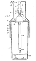
- the apparatus comprises an outer casing 2 which provides mounting means for a bottle or other container (not shown) containing a liquid to be carbonated and a carbon dioxide bulb B that itself may be of a conventional form user to produce carbonated drinks domestically, e.g. holding a charge of 8gm liquid carbon dioxide.
- the bottle is mounted in a lower part 4 of the casing and the bulb B in an upper part 6 that is detachably secured to the lower part by a toothed or threaded arrangement to be described in more detail below.
- the container upper part 6 comprises a cylindrical lower skirt 8 and a top cap 10 abutting the skirt at a peripheral junction and secured thereto by snap ribs (not shown).
- the lower skirt has a top wall 12 with a flanged central aperture 14 in which a bulb holder 16 for the bulb B is an interference fit, there also being engagement means (not shown) between the top wall and the holder to prevent relative rotation.
- the top cap 10 has an opening in its top wall that is closed by a pivoting lid 20 described in more detail below, attached to the bulb holder 16 through an offset transverse pivot mounting 22.
- the bulb holder 16 includes a downwardly open cylindrical portion 28 in which there is a sliding shuttle 30 that comprises a hollow needle 32 projecting upwardly from it towards the bulb.
- the needle is biased away from the bulb by a compression spring 34 acting between the shuttle and the top wall 36 of the holder cylindrical portion.
- a stop ring 38 at the bottom of the cylindrical portion retains the shuttle within the holder.
- the shuttle has a gas expansion tube 40 projecting downwards from it and terminating at an outlet orifice valve 42 near the bottom of the housing lower part to provide a heat transfer conduit for bulb fluid to flow into the liquid.
- the tube extends into the bottle of liquid, with the neck of the bottle sealed shuttle through its stem 52 provided with two O-rings 54 in series that act both to seal the bulb holder bore 56 in which they slide and also to centralise the needle relative to that bore.
- the central passage 50 in the shuttle connects the interior bore of the needle to a shuttle plug 62 wherein a transverse exit passage 64 is closed by an elastomeric ring 66 that acts as a non-return valve permitting fluid flow only from the shuttle into the gas expansion tube 40.
- the tube is filled with a permeable mass or matrix 68 of material acting as a heat source for evaporation and expansion of the carbon dioxide so that it can be injected into the bottle as a pressurised dry gas flow.
- the material used for this purpose is required to be able to transmit the necessary amount of heat very quickly to the carbon dioxide as it passes through the tube, since the operation of the device with a conventional size of carbon dioxide bulb may occupy no more than two or three seconds. It must also be able to recover heat from the surroundings relatively fast, as the user may want to repeat the operation every two or three minutes.
- metallic materials will therefore be preferred for the permeable mass, and the material will in any event preferably be in the form of small particles or filaments providing a multiplicity of small against a sealing disc 44 on the underside of the shuttle, the upper and lower parts of the casing 2 then being so positioned that the bottle forces the shuttle upwards, and therefore the needle also, to pierce the bulb.
- the liquid carbon in the bulb vaporises as it passes through the expansion tube where the cooling effect of the expansion is partly counteracted by heat transfer from the material of the tube, so that the formation of solid carbon dioxide is prevented and the fluid is introduced into the bottle as a dry gas to carbonate the liquid there.
- the hollow needle 32 communicates with a central passage 50 in the shuttle.
- the needle is fixed to the main body of the interstitial spaces that form paths through which the fluid flows.
- the outlet orifice valve 42 has the function of preventing flow until a certain minimum gas pressure has been established in the tube as the liquid carbon dioxide from the bulb evaporates.
- the gas from the atomising tube reaches the valve through a porous plug 74 that retains the heat yielding matrix 68 in the tube and the gas pressure acts on a valve body 76 through an entry conduit 78 that is of smaller diameter than the valve body.
- a sealing disc 80 on the end face of the body confines the pressure to the smaller area of the conduit cross-section as long as the valve body is held against the entry conduit by a compression spring 82.
- the rear of the valve body is sealed from the incoming gas pressure by an O-ring 84 and the gas can only escape into the bottle through a nozzle orifice 86.
- This is of restricted cross-section so that the pressure drop across it is above the critical value and there is a choked sonic flow through the orifice.
- One effect is that the shearing action of the relatively high speed gas flow emerging into the liquid in the bottle breaks up the flow into very small bubbles that therefore disolve more easily.
- the restricted orifice also limits the outflow rate of the gas and so maintains a required back-pressure in the atomiser tube 40.
- valve body is therefore sensitive to the pressure drop across the orifice, and the spring 82 is so arranged that it will only allow the valve to be opened when the resultant gas pressure on the full cross-section of the valve body is above the orifice critical pressure.
- the apparatus is adapted to be used with bottles of a range of different heights and diameters, e.g. with capacities of between 750 cc and 1100 cc, with heights of between 250 mm and 320 mm and diameter up to 930 mm.
- the accommodation of different bottle heights is achieved by the form of screw thread engagement provided between the upper and lower parts of the casing. This comprises groups of teeth forming, on each part, two rack-like screw thread segments 92, 94.
- the upper part segments 92 are on the skirt 8 and extend over substantially the full height of the skirt, but the lower part segments 92 occupy only the topmost maximum diameter region of the tapered casing lower part 4.
- the two segments are diametrically opposed and subtend an angle slightly less than the gap between segments on the other part. It is therefore possible to align the two casing parts so that they can be telescoped axially into each other without engaging their screw thread segments.
- the teeth of the segments are obliquely inclined to form a screw lead after said telescoping movement; as they are interengaged by relative rotation between the casing parts 4, 6 there will also be a further relative axial displacement between the parts.
- any bottle can be placed in the casing lower part 4 that reaches the top of that casing part or projects somewhat above it, and the upper part 6 is lowered onto the lower part 4 while the two pairs of screw thread segments 92, 94 are kept out of alignment, the gas expansion tube 40 being inserted into the container neck in this movement.
- the casing upper part will come to rest on the bottle with the sealing disc 44 bearing on the top lip of the bottle, and when the upper part is then rotated, the screw thread segments will engage and the upper part will be forced further downwards, firstly to engage the sealing disc firmly with the bottle lip and secondly to urge the shuttle 30 upwards relative to the bulb holder 16 so that the hollow needle 32 pushes the bulb against the closed lid 20 and is forced into the bulb interior.
- the bulb cannot be pierced and the contents expressed until the pivotable lid 20 is properly positioned to resist upwards movement of the bulb, i.e. with the edges 46, 48 abutting, and the bottle lip is tightly engaged with the shuttle bottom sealing disc 44.
- the smaller groups of teeth forming the segments 94 of the casing lower part are engaged with the topmost portions of the larger groups of teeth forming the segments 92 of the casing upper part, which is then substantially at its lowermost position on the casing lower part. It will be clear that if a taller bottle is used that projects above the top of the casing lower part, the apparatus will act in the same manner but the segments of the casing lower part will engage a lower region of the casing upper part segments, as determined by the position at which the casing upper part comes to rest on the bottle lip at the end of the initial telescoping movement. It is to be understood that it is also possible to reverse the arrangement of segments illustrated, so that the smaller groups of teeth are on the casing upper part and the larger groups on the lower part.
- ribs 96 may have different diameters, but they will be centered by a series of symmetrically arranged resiliently flexible ribs 96 at the bottom of the casing lower part interior. These ribs starting from radial positions spaced from the centre of the base, extend upwardly towards their outer ends at the peripheral wall 98 to which they are connected in web-like manner, and will therefore tend to centre the bottle, in particular when a downwards pressure begins to be applied to the bottle by the screw engagement of the casing upper part.
- a blow-out disc 102 (Fig. 2) of elastomeric material is mounted on the piston 104 of the shuttle. This is positioned behind a small aperture 106 in the sealing disc 44 that is located near the disc inner periphery to ensure it will open into the top of the bottle inwardly of the top lip. Behind the blow-out disc 102 there is a larger aperture 108 in the piston 104 so that the disc is supported only around a peripheral margin. At a predetermined pressure in the bottle, therefore, the flexible blow-out disc will be deformed sufficiently for it to be driven through the aperture 108 and so leave an open passage for relief of the pressure in the bottle.
- the guide means comprise a projecting rib 110 on that casing part 112 carrying the smaller screw thread segments 94, and a thickened rim 114 on the other casing part 116 preceding and circumferentially coincident with the larger screw thread segments 92 there, with a recess 118 in that rim for the passage of the rib 110.
- the part 112 as illustrated corresponds to the casing lower part 4 in Fig. 1, and the part 116 corresponds to the upper part 6.
- the rib is disposed between the segments 94 of its casing part. It terminates with a tapered outer end extending to adjacent its casing part rim, axially slightly beyond the segments 94, and its opposite end extends axially to the level of the inner end of those segments.
- the rib does not project radially beyond the root radius of the teeth of its associated segments. This means that when the two casing parts are being assembled together, and the rib 110 has passed through the recess 118 in the thickened rim 114 of the other casing part it can then move freely over the screw thread segments of that other casing part.
- the user When assembling the casing upper and lower parts together, therefore the user first approximately locates the upper part on the lower part, and as they are brought together the tapered end of the rib 110 will provide the correct orientation between the parts as it engages the recess 118. While the rib is in the recess, relative rotational movement between the two casing parts is prevented, so that the screw thread segments cannot be engaged until the rib has passed completely through the recess, and the smaller groups of threads 94 have similarly passed through the gaps between the arcuate portions of the rim 114. At that stage the complete axial length of the smaller segments will be engageable with the segments of the other casing part. It is therefore ensured that the two casing parts will be securely fastened together with a sufficient number of segment teeth interengaged.
- Fig. 10 illustrates a number of diffeent forms of permeable mass or matrix that can be used in the gas expansion tube 40, although not necessarily all in the same tube.
- the figure shows a spiral of tightly rolled wire gauze 120, a pile of wire gauze discs 121, or a mass of particles 122, or a random, flocculant mass of wire or thin strip 123 in each case tightly fitting within the inside profile of the tube cross-section.
- Porous retainers 124 are fixed in the tube to hold the permeable mass in place.
- the tube cross-section may take a variety of forms and Figs. 10a, 10b and 10c illustrate some examples. The latter two examples can be assembled in honeycomb fashion to form a group of small cross-section flow passages in series and/or parallel connection, with interposed sheet-like electric heating elements if desired.
- Fig. Ila shows a modified expansion tube 40a with an inlet 126 to an annular space 127 containing the porous mass 68 into which a tubular enclosure 128 is inserted containing a tubular heating element 129.
- a communicating region below the bottom end of the enclosure 128 between the inner and outer regions of the annular space and at the top of the conduit an end space 130 communicates with a central exit tube 131 to the outlet 132.
- Transverse porous retainers 124 are provided if the porous mass in loose powder form but may not be necessary if it is in the form of spirally wound wire gauze.
- the wet fluid entering at 126 is constrained by the enclosure 128 to flow through the porous mass, first downwards through the outer region of the annular space 127 and then upwards through its inner region, before exiting via the tube 131.
- the tubular electrical element is operated to transfer heat to the porous mass by conduction and may be energised continuously while successive charges of fluid are passed through the apparatus.
- Fig. llb shows another modified expansion tube 40b filled with the porous mass 68, retained if necessary by partition 124, and two metal combs 134 at opposite ends of the conduit which penetrate longitudinally into the porous mass in electrical contact therewith to enable an electric current to be passed directly through the mass, which is of an electrically conductive material and which by virtue of the voids therein has sufficient resistance to generate a heating effect within the mass.
- the material of the conduit 40b must be of sufficient electrical resistance so as not to short- circuit the current path through the mass. Many suitable materials such as quartz or ceramics are commercially available.
- Fig. llc shows an arrangement in which an electric inductance winding 136 surrounds the tube 40c.
- the material of the tube or conduit is chosen so as not to screen the porous mass and inhibit the induction of eddy currents within the mass.
- the porous mass is preferably sintered as described above.
- Fig. 12a shows an example of the construction of an expansion tube or conduit 40d with a multiplicity of longitudinal inwardly projecting radial ribs 142 to form the extended internal surface area.
- These ribs may extend to the centre of the conduit or there may be a significant central core space filled with porous mass 68, in this instance in wire form in any of the configurations already described.
- porous mass 68 in this instance in wire form in any of the configurations already described.
- an analogous extension of the conduit internal surfaces may be obtained if the conduit wall has a lobed configuration: this also results in an extended external surface area.
- Fig. 12b shows an alternative construction of an expansion tube or conduit 40e with an internal helical fin 144 to increase the contact area for the porous mass.
- F ig. 12c shows the finning as a six-start helix 144a. This latter figure also illustrates the packing of the interior of the tube with the porous mass, which fills the tube to its cylindrical wall although the fins are shown uncovered for clarity.
- a tube or conduit 40f with a series of concentric tubes 146 in it, each with perforations 147 around its walls adjacent opposite ends.
- the annular spaces between alternate pairs of the tubes have porous end rings 148 to contain the porous mass 68 that may fill all the annular spaces if extra heat exchange capacity is required.
- An end plate 149 closes the annular spaces off remote from the tube inlet end, so that in alternate annular spaces the fluid is constrained to flow downwards and in the intervening spaces it is constrained to flow upwards.
- the concentric tubes may be provided with rib 150 the main purpose of which is to enhance the transmission of recuperative heat from the surroundings.
- Figs. 14a and 14b show examples of non-return valves 152 and 153 which may be incorporated respectively at the inlet 126 and at the outlet 132 of the conduit.
- the inlet valve comprises an elastomeric sleeve 154 in tension in an annular recess to cover a transverse hole 156 communicating with the inlet 126, as in a so-called Woods valve commonly used in pedal cycles, and is arranged to open at a very low superpressure on its inlet side.
- the outlet valve comprises a ball 157 urged onto a conical seating face 158 by a spring 159. Both valves are separated from the porous mass 68 by the partitions 124 and both are shown with O-rings 160 to prevent leakage of the fluid.
- Fig. 15 illustrates a modified form of outlet orifice valve 172, in which parts already described with reference to the orifice valve 42 in Fig. 1 are indicated by the same reference numbers.
- a valve body 174 is moulded integrally with a diaphragm 176 from a rubbery material.
- the diaphragm outer edge engages in a recess 178 in the inner wall of the valve housing, beyond the nozzle orifice 86, and the resilience of the diaphragm provides the biasing force that holds the valve body on its seating.
- the valve operates in the same manner as the first-described example.
- this apparatus also has upper and lower casing parts engageable by screw thread segments in the manner described above, with the container for the liquid to be gasified being inserted in the lower casing part (not shown) and a conventional 8 gm liquified carbon dioxide bulb B inserted in a bulb holder 200 in the upper casing part.
- the figure shows only the top wall 202 of the lower skirt of the upper casing part, on which lower skirt the segments of the upper casing part are formed.
- a hollow needle 204 is mounted in a shuttle 206 slidable in the bulb holder and urged downwards by a spring 208.
- On the underface of the shuttle is resilient sealing disc 212 for engagement with the mouth of the container in the lower casing part, and engagement of the screw thread portions of the upper and lower casing parts is arranged to urge the container mouth into firm sealing engagement with the disc and to force the needle to pierce the bulb so that gas under pressure can flow through the gas expansion tube into the liquid in the container.
- the shuttle now comprises, immediately below the needle, an enlarged cylindrical portion or barrel 214 that is slidable into a bore 216 of a spool, two different forms of which are illustrated in the two halves of Fig. 16 and indicated by references 218a and 218b.
- the spool has an integral collar 210 below the barrel.
- the spring 208 acts on the spool so that the shuttle and spool are urged apart, but the collar 210 limits this relative movement when it engages the underside of the barrel.
- the movement of the spool is limited by a retaining clip 220 that projects through the wall of the bulb holder into a cylindrical recess 222 in the spool, and Fig. 16 shows the spool and shuttle in their lowermost positions.
- FIG. 16 there is an upper O-ring 224 mounted in the spool bore, to seal with the neck of the bulb B that has been inserted to rest upon a locating ring 225, and a lower O-ring 226 is mounted on the barrel 214 to form a seal between the barrel and the spool 218a when the shuttle is urged towards the bulb.
- a small hole 227 provides a vent for excess pressure from the spool interior between the O-rings when the barrel withdraws to a lowermost position relative to the spool, at the end of a charging operation.
- the bulb is engaged by a sealing sleeve 228 which both seals against the neck of the capsule and limits its movement downwards into the bulb holder.
- the sealing sleeve is inserted into the spool 218b before a retaining ring 230 is applied to secure the sleeve in place.
- a lower 0-ring.216 is mounted on the barrel 214 to form a seal between the barrel and the spool bore when the shuttle is urged towards the bulb.
- a vent hole is not required in this instance because gas can escape past the seal 228 when the axial sealing loading is relieved as the barrel is withdrawn.
- the effective seal diameter between the bulb and the seal as provided by the 0 -ring 224 or the sealing sleeve 228, either smaller than or equal to the effective seal diameter between the spool and the needle barrel, an increase of pressure in the space between the two seals will not produce a resultant force tending to force the spool downwards away from the bulb.
- the barrel has a maximum permissible diameter. Otherwise, the increase of the container relief pressure, i.e. the pressure at which the shuttle is lifted to vent the container interior, would become excessively high as the pressure in the spool bore increases. Therefore, the measures taken to ensure that the neck of the bulb remains sealed in the spool must also be effective with the diameter of the barrel limited to the extent necessary to ensure the container pressure will be relieved in safety.
- Both embodiments illustrated in Fig. 16 operate in a similar manner.
- the liquified gas bulb is inserted in the bulb holder 200 in the upper casing part and a liquid-filled container is inserted into the lower casing part.
- the spool 218a or 218b is in its lowermost position, with the upper shoulder of the cylindrical recess resting on the retaining clip 220, and shuttle 206 is also in its lowermost position, depending from the spool collar 210.
- the upper casing part has a pivoting lid of the form describd above, mounted on the stub pivots 232 and this is closed once the bulb is inserted.
- the container mouth engages the sealing disc to seal against it and in so doing urges the shuttle upwards.
- the casing upper part will move downwards while the bulb and spool remain in the same positions relative to each other and the container, until the closed top lid comes into contact with the top of the bulb.
- the axial telescoping movement between the upper and lower casing parts is completed, and the casing top part is supported through the spring 208, with the needle still spaced from the bulb. If the screw thread portions of the two parts are now engaged the bulb is brought down onto the needle and the needle is forced into the bulb to release its contents through the gas expansion tube into the liquid in the container.
- the needle does not begin to pierce the bulb until the screw thread portions are partly engaged, it is possible to ensure that the two parts are securely interconnected before the apparatus begins to be pressurised. For example, if the screw thread portions are 90 0 segments it may be arranged that about one third of the full angular engagement of the thread portions is completed before the needle begins to pierce the bulb.
- the screw thread portions between the casing part cannot apply the force required to pierce the bulb.
- the lid cannot be closed after the upper casing part has been lowered onto the lower casing part because with the lid open at that stage the bulb will have been pushed to a position in which it blocks closure of the lid.
- a preferred form of pressure relief means for apparatus otherwise of the form already described comprises sealing means having a planar annular sealing member 302 of silicone rubber or food quality natural rubber mounted on a rigid backing member 304 that forms a cast or moulded shuttle providing gas throughflow means.
- Other features of the apparatus are not shown, but as in the previously described embodiments it comprises a casing in which the shuttle is axially slidable in the directions X,Y and is urged in the direction Y by a spring against the open lip of the bottle which is mounted substantially coaxially with the shuttle in the casing, the lip thereby being held in sealing engagement with the end face 302a of the flexible sealing member.
- a screw-threaded section 305 is shown to which the gas expansion tube 40 is secured, and the apparatus also comprises unillustrated means by which, as the sealing engagement is made, a carbon dioxide bulb or capsule is pierced and its contents flow through the central axial passage 306 in the shuttle member to an outlet nozzle 308 where there is a non-return valve 310 and to the bottle, which has previously been filled with water.
- the non-return valve leads to a heat transfer conduit (not shown) where the bulb fluid is expanded to a dry gas as it flows into the bottle.
- the supporting surface 314 of the shuttle providing the backing member for the sealing member and through which the sealing pressure between the flexible member and the bottle lip is transmitted, has two opposite radially elongate recesses or slots 316. At these two positions, therefore, the flexible member is unsupported and can move away from the bottle lip.
- the bottle internal pressure can rise considerably before the gas dissolves in the liquid, and the sealing member will flex at the unsupported portions when the bottle internal pressure passes above some predetermined value, since the slots are themselves open to ambient air pressure. Gas will then be vented from the bottle until the pressure has dropped sufficiently to allow the flexible member to return into full sealing engagement with the bottle lip.
- the flexural compliance of the unsupported portions in front of the slots 16 can be controlled to set the required safety blow-off pressure.
- blow-off pressure is independent of the force with which the sealing means is held against the bottle lip, since the sealing member is still. held in the same position against the bottle lip while its unsupported portions are flexed by the gas pressure. No complex and sensitive mechanism is required, therefore, and during normal operation it is always possible to provide a secure seal for the charging process.
- Figs. 20 and 21 show an alternative flexible sealing member 322 that can be employed with a backing member 324 having a planar supporting surface 326, in an arrangement otherwise similar to that in Figs. 17 to 19.
- a central axial passage 328 for the injection of gas into the bottle through a non-return valve and a heat exchange conduit as already described, this not being illustrated in any detail.
- a planar face 330 of the flexible member faces the sealing face of the bottle lip, but at its rear face the member has four equispaced radial recesses 332 which result in there being corresponding thin-walled unsupported portions 334 at the front face.
- the unsupported portions are flexurally compliant and can be proportioned so as to allow gas to escape once a certain pressure has been exceeded.
- Fig. 21 also illustrates how, even with the bottle lip L eccentric to the sealing means, the pressure relief function of the sealing means is equally effective. It will be apparent from this that the flexural compliance of the reduced thickness portions to the bottle internal gas pressure is dependent on the circumferential extent of those portions but not on the radial position of contact of the bottle lip. It will be understood that a similar effect can be obtained using a single radial recess or slot, although it is preferred to provide two or more angularly spaced recesses or slots as this caters for a greater range of eccentricity within given overall dimensions.
- FIGs. 22 and 23 an embodiment of the invention is illustrated similar to the preceding example but in which a planar flexible member 342 is supported by a backing face 344 on a shuttle 346 in which the radial recesses or slots are replaced by an equispaced series of shorter recesses or slots 348 arranged on a pitch circle concentric with the shuttle axis and corresponding to the bottle lip diameter.
- the areas of the flexible member overlying these slots thus form portions of greater flexural compliance than the remainder of the member.
- the slots will be entirely outside or inside the area encircled by the bottle lip and so not be operative for the relief of the internal bottle pressure, but there is a sufficient number of slots to ensure that one or more of them will substantially coincide radially with the bottle lip L, whatever its eccentricity, and so provide the pressure relief function. Therefore, it is also possible in this case to cope with a considerable radial offset of the bottle relative to the shuttle. In other respects, this embodiment can operate in the manner already described.
Landscapes
- Chemical & Material Sciences (AREA)
- Chemical Kinetics & Catalysis (AREA)
- Health & Medical Sciences (AREA)
- Nutrition Science (AREA)
- Life Sciences & Earth Sciences (AREA)
- Engineering & Computer Science (AREA)
- Food Science & Technology (AREA)
- Polymers & Plastics (AREA)
- Feeding, Discharge, Calcimining, Fusing, And Gas-Generation Devices (AREA)
- Filling Or Discharging Of Gas Storage Vessels (AREA)
- Containers And Packaging Bodies Having A Special Means To Remove Contents (AREA)
Priority Applications (1)
| Application Number | Priority Date | Filing Date | Title |
|---|---|---|---|
| AT81303964T ATE16767T1 (de) | 1980-09-01 | 1981-08-28 | Vorrichtung fuer die vergasung eines fluids. |
Applications Claiming Priority (8)
| Application Number | Priority Date | Filing Date | Title |
|---|---|---|---|
| GB8028130 | 1980-09-01 | ||
| GB8028130 | 1980-09-01 | ||
| GB8032809 | 1980-10-10 | ||
| GB8032809 | 1980-10-10 | ||
| GB8109914 | 1981-03-30 | ||
| GB8109914 | 1981-03-30 | ||
| GB8123433 | 1981-07-30 | ||
| GB8123433 | 1981-07-30 |
Related Child Applications (2)
| Application Number | Title | Priority Date | Filing Date |
|---|---|---|---|
| EP84107491.7 Division-Into | 1981-08-28 | ||
| EP84107491A Division EP0127197A3 (de) | 1980-10-10 | 1981-08-28 | Gerät mit Mitteln versehen zum Ablassen einer Fluidumspannung |
Publications (3)
| Publication Number | Publication Date |
|---|---|
| EP0047163A2 true EP0047163A2 (de) | 1982-03-10 |
| EP0047163A3 EP0047163A3 (en) | 1982-05-26 |
| EP0047163B1 EP0047163B1 (de) | 1985-12-04 |
Family
ID=27449201
Family Applications (1)
| Application Number | Title | Priority Date | Filing Date |
|---|---|---|---|
| EP81303964A Expired EP0047163B1 (de) | 1980-09-01 | 1981-08-28 | Vorrichtung für die Vergasung eines Fluids |
Country Status (9)
| Country | Link |
|---|---|
| US (1) | US4457877A (de) |
| EP (1) | EP0047163B1 (de) |
| JP (1) | JPH024332B2 (de) |
| AU (2) | AU547876B2 (de) |
| BR (1) | BR8108772A (de) |
| DE (1) | DE3173132D1 (de) |
| DK (1) | DK192182A (de) |
| NZ (1) | NZ198214A (de) |
| WO (1) | WO1982000778A2 (de) |
Cited By (6)
| Publication number | Priority date | Publication date | Assignee | Title |
|---|---|---|---|---|
| WO1984004024A1 (en) * | 1983-04-08 | 1984-10-25 | Sodastream Ltd | Liquid carbonating apparatus |
| EP2589567A1 (de) * | 2011-11-03 | 2013-05-08 | Sodasparkle International Limited | Vorrichtung zur Herstellung von kohlensäurehaltigem Wasser |
| EP3086018A1 (de) * | 2015-04-20 | 2016-10-26 | Linde Aktiengesellschaft | Zylinderexklusivverbindung |
| EP3130833A1 (de) * | 2015-08-13 | 2017-02-15 | Linde Aktiengesellschaft | Gaszylinder mit mehrfachdichtung |
| CN110117143A (zh) * | 2019-05-10 | 2019-08-13 | 大成科创基础建设股份有限公司 | 一种镁基复合材料固化泥浆的方法 |
| CN113230915A (zh) * | 2021-06-16 | 2021-08-10 | 周伟 | 一种节能型尿素溶解罐热量循环利用系统 |
Families Citing this family (22)
| Publication number | Priority date | Publication date | Assignee | Title |
|---|---|---|---|---|
| US4526730A (en) * | 1983-01-31 | 1985-07-02 | Cochran Daniel M | Home carbonating apparatus |
| DE3579893D1 (de) * | 1984-05-16 | 1990-10-31 | Cosmonor Sa | Verfahren zum zusammensetzen von einheitsmengen mit vorgefuellten spritzen oder vorgefuellten zerstaeubern. |
| GB2175681B (en) * | 1985-01-28 | 1988-10-19 | Nb Marketing Co Pty Ltd | Carbonating head |
| US4867209A (en) * | 1987-10-29 | 1989-09-19 | United Soda, Inc. | Portable hand holdable carbonating apparatus |
| US5027952A (en) * | 1989-02-28 | 1991-07-02 | Nch Corporation | Plastic bottle for acid drain opening system |
| US4969491A (en) * | 1989-02-28 | 1990-11-13 | Nch Corporation | Acid drain opening system |
| US5112539A (en) * | 1990-01-29 | 1992-05-12 | Dietmar Parnet | Beverage carbonating, cooling and dispensing system |
| US5635232A (en) * | 1994-11-23 | 1997-06-03 | Perlage Systems, Inc. | Safe method and apparatus for preserving and re-carbonating beverages |
| DE19754686A1 (de) * | 1997-12-10 | 1999-06-17 | Messer Griesheim Gmbh | Verfahren und Vorrichtung zum Eintragen von Gas in eine Flüssigkeit |
| US6038784A (en) * | 1998-07-10 | 2000-03-21 | Dunn; Steven B. | Bottle rack |
| FR2807821A1 (fr) * | 2000-04-13 | 2001-10-19 | Air Liquide | Detenteur de fluide avec rechauffeur integre |
| EP1642637A1 (de) * | 2004-09-29 | 2006-04-05 | Soda-Club Ltd | Vorrichtung zum Karbonisieren einer Flüssigkeit mit einem Druckgas |
| US20110215485A1 (en) * | 2010-03-08 | 2011-09-08 | Steinberg Benjamin H | Home carbonator designed to work with used consumer product bottles; especially used drink bottles |
| JP5331093B2 (ja) * | 2010-12-06 | 2013-10-30 | 株式会社ニクニ | 液処理装置 |
| ITMI20111831A1 (it) * | 2011-10-07 | 2013-04-08 | Sparkling Drink Systems Innovation Ct Ltd | Dispositivo gasatore. |
| GB2496456B (en) * | 2011-11-14 | 2017-07-19 | Linde Ag | Gas supply device |
| AT517242B1 (de) * | 2015-06-11 | 2019-05-15 | Innveri Ag | Vorrichtung zum Konservieren von Getränken |
| IL249778B (en) * | 2016-12-26 | 2018-04-30 | Hay Dror | A self-carbonating beverage container |
| US10716452B2 (en) | 2017-02-23 | 2020-07-21 | Munchkin, Inc. | Compact drying rack |
| TWM556715U (zh) * | 2017-04-14 | 2018-03-11 | 岳造宇 | 可攜式氣泡水瓶 |
| US10898868B2 (en) | 2017-04-14 | 2021-01-26 | Chao-Yu Yueh | Portable bubble water bottle |
| US11045774B2 (en) * | 2018-12-21 | 2021-06-29 | EMDOTEM S.r.L. | Container for liquids associated with a carbonator |
Citations (9)
| Publication number | Priority date | Publication date | Assignee | Title |
|---|---|---|---|---|
| US1905986A (en) * | 1930-09-05 | 1933-04-25 | Syphonator Company Ltd | Beverage carbonating and dispensing apparatus |
| GB783230A (en) * | 1954-11-08 | 1957-09-18 | Fizzmaster Corp | Device for carbonating beverages |
| FR1257843A (fr) * | 1960-02-26 | 1961-04-07 | Soudure Autogene Francaise | Procédé et dispositif pour la vaporisation du gaz carbonique liquéfié |
| FR1284324A (fr) * | 1961-03-20 | 1962-02-09 | Distributeur de gaz | |
| FR1331828A (fr) * | 1962-08-22 | 1963-07-05 | Appareil pour évaporer et chauffer ou surchauffer le bioxyde de carbone liquide | |
| FR1379049A (fr) * | 1963-10-09 | 1964-11-20 | Carbonique | Dispositif de réchauffage de gaz comprimés et liquéfiés en vue de leur utilisation après détente, sans givrage |
| GB1453363A (en) * | 1974-04-24 | 1976-10-20 | Sodastream Ltd | Apparatus for aerating liquids |
| GB2026882A (en) * | 1978-08-02 | 1980-02-13 | Thorn Svenska | Appliance for making an aerated beverage |
| US4189068A (en) * | 1976-09-30 | 1980-02-19 | Waterlomat, Societe Anonyme | Perforating and sealing device for carbon dioxide capsules and suchlike |
Family Cites Families (29)
| Publication number | Priority date | Publication date | Assignee | Title |
|---|---|---|---|---|
| DE268927C (de) * | ||||
| GB119514A (en) * | 1917-10-01 | 1918-10-01 | William Millar | Improvements in Mine Signalling Apparatus. |
| US1592305A (en) * | 1921-03-25 | 1926-07-13 | Harry H Lewis | Carbonating apparatus |
| GB365570A (en) * | 1929-07-12 | 1932-01-15 | Gustav Bojner | Oblique rotatable drum for carrying out heat technical processes |
| US2073273A (en) * | 1931-11-25 | 1937-03-09 | Korn Erna | Means for preparing beverages |
| GB399352A (en) * | 1932-12-24 | 1933-10-05 | Nikolaus Meurer | New or improved method of aerating beverages, and apparatus therefor |
| FR779459A (fr) * | 1934-09-13 | 1935-04-05 | Chauvin & Compagine Ets | Procédé et appareillage perfectionnés pour la saturation, par l'acide carbonique, de tous liquides et boissons |
| GB472600A (en) * | 1936-03-23 | 1937-09-23 | Johan Sigismund Fasting | Improvements in apparatus for drying or heating slurry or the like |
| US2132011A (en) * | 1936-07-17 | 1938-10-04 | Budwig Mfg Company | Beverage dispensing apparatus |
| GB485258A (en) * | 1937-08-28 | 1938-05-17 | Carl Fabian Lozon | Improvements in or relating to apparatus for carbonating or aerating liquids |
| US2254587A (en) * | 1937-11-09 | 1941-09-02 | Linde Air Prod Co | Apparatus for dispensing gas material |
| US2229441A (en) * | 1938-05-31 | 1941-01-21 | Automatic Canteen Company | Carbonator |
| GB538937A (en) * | 1940-04-30 | 1941-08-21 | Manfred Sussmann | Improvements in and relating to apparatus for use in the carbonation of liquids |
| US2336708A (en) * | 1940-07-29 | 1943-12-14 | Knapp Monarch Co | Charging mechanism for aerators and the like |
| US2339640A (en) * | 1940-08-03 | 1944-01-18 | Carl J Holinger | Liquid carbonation |
| GB571114A (en) * | 1943-07-09 | 1945-08-08 | Herts Pharmaceuticals Ltd | Method for the pyrolytic decomposition of organic compounds |
| US2545233A (en) * | 1946-12-19 | 1951-03-13 | Kaufman Daniel | Filling plug for oil tanks or the like |
| US2805846A (en) * | 1954-11-08 | 1957-09-10 | Dewan Leon | Device for carbonating beverages |
| US2794452A (en) * | 1955-01-31 | 1957-06-04 | Ranold F Quam | Valves for pressure jugs or the like |
| GB823297A (en) * | 1956-03-09 | 1959-11-11 | Cassella Farbwerke Mainkur Ag | Process for the separation of mixtures of liquids |
| GB838552A (en) * | 1957-07-09 | 1960-06-22 | British Oxygen Co Ltd | Converter for liquefied gases |
| US3005475A (en) * | 1960-06-13 | 1961-10-24 | Jr Richard W Beall | Combined liquid dispensing and air venting apparatus |
| US3151467A (en) * | 1961-12-04 | 1964-10-06 | Union Carbide Corp | Process and apparatus for the filling, transportation and dispensing of hazardous fluids |
| DE1532530A1 (de) * | 1966-06-04 | 1970-01-15 | Holstein & Kappert Maschf | Fuellrohrloses Fuellventil |
| US3473704A (en) * | 1967-04-18 | 1969-10-21 | Valve Corp Of America | Venting valve construction for refillable pressurized dispensers |
| GB1289551A (de) * | 1969-01-23 | 1972-09-20 | ||
| US3591962A (en) * | 1969-03-26 | 1971-07-13 | Systems Capital Corp | Cryogenic power source for starting jet engines |
| US4011288A (en) * | 1975-03-14 | 1977-03-08 | Baxter Travenol Laboratories, Inc. | Disposable humidifier assembly |
| GB2049454B (en) * | 1979-05-14 | 1982-12-15 | Thorn Cascade Co Ltd | Appliance for making an aerated beverage |
-
1981
- 1981-08-28 DE DE8181303964T patent/DE3173132D1/de not_active Expired
- 1981-08-28 BR BR8108772A patent/BR8108772A/pt unknown
- 1981-08-28 US US06/373,493 patent/US4457877A/en not_active Expired - Fee Related
- 1981-08-28 WO PCT/GB1981/000173 patent/WO1982000778A2/en unknown
- 1981-08-28 EP EP81303964A patent/EP0047163B1/de not_active Expired
- 1981-08-28 AU AU75337/81A patent/AU547876B2/en not_active Ceased
- 1981-08-28 JP JP56502819A patent/JPH024332B2/ja not_active Expired - Lifetime
- 1981-08-31 NZ NZ198214A patent/NZ198214A/en unknown
-
1982
- 1982-04-29 DK DK192182A patent/DK192182A/da not_active Application Discontinuation
-
1985
- 1985-08-05 AU AU45787/85A patent/AU4578785A/en not_active Abandoned
Patent Citations (9)
| Publication number | Priority date | Publication date | Assignee | Title |
|---|---|---|---|---|
| US1905986A (en) * | 1930-09-05 | 1933-04-25 | Syphonator Company Ltd | Beverage carbonating and dispensing apparatus |
| GB783230A (en) * | 1954-11-08 | 1957-09-18 | Fizzmaster Corp | Device for carbonating beverages |
| FR1257843A (fr) * | 1960-02-26 | 1961-04-07 | Soudure Autogene Francaise | Procédé et dispositif pour la vaporisation du gaz carbonique liquéfié |
| FR1284324A (fr) * | 1961-03-20 | 1962-02-09 | Distributeur de gaz | |
| FR1331828A (fr) * | 1962-08-22 | 1963-07-05 | Appareil pour évaporer et chauffer ou surchauffer le bioxyde de carbone liquide | |
| FR1379049A (fr) * | 1963-10-09 | 1964-11-20 | Carbonique | Dispositif de réchauffage de gaz comprimés et liquéfiés en vue de leur utilisation après détente, sans givrage |
| GB1453363A (en) * | 1974-04-24 | 1976-10-20 | Sodastream Ltd | Apparatus for aerating liquids |
| US4189068A (en) * | 1976-09-30 | 1980-02-19 | Waterlomat, Societe Anonyme | Perforating and sealing device for carbon dioxide capsules and suchlike |
| GB2026882A (en) * | 1978-08-02 | 1980-02-13 | Thorn Svenska | Appliance for making an aerated beverage |
Cited By (10)
| Publication number | Priority date | Publication date | Assignee | Title |
|---|---|---|---|---|
| WO1984004024A1 (en) * | 1983-04-08 | 1984-10-25 | Sodastream Ltd | Liquid carbonating apparatus |
| EP2589567A1 (de) * | 2011-11-03 | 2013-05-08 | Sodasparkle International Limited | Vorrichtung zur Herstellung von kohlensäurehaltigem Wasser |
| EP3086018A1 (de) * | 2015-04-20 | 2016-10-26 | Linde Aktiengesellschaft | Zylinderexklusivverbindung |
| TWI621801B (zh) * | 2015-04-20 | 2018-04-21 | 林德股份公司 | 聯接裝置及氣缸 |
| EP3130833A1 (de) * | 2015-08-13 | 2017-02-15 | Linde Aktiengesellschaft | Gaszylinder mit mehrfachdichtung |
| WO2017025174A1 (en) * | 2015-08-13 | 2017-02-16 | Linde Aktiengesellschaft | A multiple seal gas cylinder |
| CN110117143A (zh) * | 2019-05-10 | 2019-08-13 | 大成科创基础建设股份有限公司 | 一种镁基复合材料固化泥浆的方法 |
| CN110117143B (zh) * | 2019-05-10 | 2021-09-17 | 大成科创基础建设股份有限公司 | 一种镁基复合材料固化泥浆的方法 |
| CN113230915A (zh) * | 2021-06-16 | 2021-08-10 | 周伟 | 一种节能型尿素溶解罐热量循环利用系统 |
| CN113230915B (zh) * | 2021-06-16 | 2022-12-27 | 内蒙古天润化肥股份有限公司 | 一种节能型尿素溶解罐热量循环利用系统 |
Also Published As
| Publication number | Publication date |
|---|---|
| DK192182A (da) | 1982-04-29 |
| EP0047163A3 (en) | 1982-05-26 |
| AU547876B2 (en) | 1985-11-07 |
| JPS57501314A (de) | 1982-07-29 |
| AU7533781A (en) | 1982-04-05 |
| WO1982000778A3 (en) | 1982-05-13 |
| JPH024332B2 (de) | 1990-01-26 |
| US4457877A (en) | 1984-07-03 |
| NZ198214A (en) | 1985-04-30 |
| EP0047163B1 (de) | 1985-12-04 |
| DE3173132D1 (en) | 1986-01-16 |
| BR8108772A (pt) | 1982-07-06 |
| WO1982000778A2 (en) | 1982-03-18 |
| AU4578785A (en) | 1985-11-07 |
Similar Documents
| Publication | Publication Date | Title |
|---|---|---|
| US4457877A (en) | Fluid gasification apparatus | |
| US4341000A (en) | Method of charging heat pipe | |
| KR890002990B1 (ko) | 유체 저장용기 | |
| US4154378A (en) | Metering valve for pressurized container | |
| US4997555A (en) | Fuel filter assembly with heater | |
| CN102245949B (zh) | 温度感应型流体流动控制设备 | |
| US20150274537A1 (en) | Dry ice dispensing apparatus | |
| EP1185464A1 (de) | Mischvorrichtung zum zumischen von additiven in eine verpackte flüssigkheit | |
| WO2018172429A1 (en) | Flavor delivery system | |
| JPH06201099A (ja) | 再充填阻止弁 | |
| BR0307258B1 (pt) | Dispositivo de regulagem de pressão para um vaso de distruibuição pressurizado e métodos de montagem e instalação do mesmo | |
| KR19980701835A (ko) | 증발 베이스부를 구비하고 헤드부에 필터가 설치된 오일 재생장치 | |
| KR101547957B1 (ko) | 핵융합반응용 비접촉 미분진 누설 방지식 삼중수소 용기 | |
| WO1994001728A1 (en) | Method and apparatus for collecting liquid cryogen | |
| US5198222A (en) | Time release bolus | |
| US3523006A (en) | Gas flow regulator for lighter | |
| EP1413529B1 (de) | Einstellbares Dosierventil zur Abgabe von unter Druck stehenden Flüssigkeiten | |
| EP0073196A1 (de) | Durch ein fluidum betätigte membranpumpe | |
| JPH01501057A (ja) | 凝縮ガスの投与装置 | |
| RU2006138183A (ru) | Разливочный аппарат, снижающий потери газа, растворенного в выпускаемой жидкости, и способ поддержания повышенного давления в емкости | |
| JP2002529333A (ja) | 液体を所定レベルに充填する自動液体充填装置及び方法 | |
| EP0061191A1 (de) | Metallhydridreaktor | |
| KR100532231B1 (ko) | 수소가스 저장장치 | |
| CN215489090U (zh) | 一种带可调式限充装置的液化石油气瓶阀 | |
| CN210311744U (zh) | 一种饮用瓶 |
Legal Events
| Date | Code | Title | Description |
|---|---|---|---|
| PUAI | Public reference made under article 153(3) epc to a published international application that has entered the european phase |
Free format text: ORIGINAL CODE: 0009012 |
|
| AK | Designated contracting states |
Designated state(s): AT BE CH DE FR GB IT LU NL SE |
|
| PUAL | Search report despatched |
Free format text: ORIGINAL CODE: 0009013 |
|
| AK | Designated contracting states |
Designated state(s): AT BE CH DE FR GB IT LU NL SE |
|
| 17P | Request for examination filed |
Effective date: 19821104 |
|
| ITF | It: translation for a ep patent filed | ||
| RAP1 | Party data changed (applicant data changed or rights of an application transferred) |
Owner name: RAFIQUE, SYED OMAR ZIKRIA MUBARAK Owner name: M.I.Y. HOME SYSTEMS LIMITED |
|
| RIN1 | Information on inventor provided before grant (corrected) |
Inventor name: RAFIQUE, SYED OMAR ZIKRIA MUBARAK |
|
| RIN1 | Information on inventor provided before grant (corrected) |
Inventor name: RAFIQUE, SYED OMAR ZIKRIA MUBARAK Inventor name: LOVE, JAMES PRICE |
|
| RAP1 | Party data changed (applicant data changed or rights of an application transferred) |
Owner name: M.I.Y. HOME SYSTEMS LIMITED |
|
| GRAA | (expected) grant |
Free format text: ORIGINAL CODE: 0009210 |
|
| AK | Designated contracting states |
Designated state(s): AT BE CH DE FR GB IT LI LU NL SE |
|
| REF | Corresponds to: |
Ref document number: 16767 Country of ref document: AT Date of ref document: 19851215 Kind code of ref document: T |
|
| BECA | Be: change of holder's address |
Free format text: 851204 *KARL FISCHER-POCHTLER G.M.B.H.KURSCHNERGASSE 4, AT-1210 WIEN |
|
| BECH | Be: change of holder |
Free format text: 851204 *KARL FISCHER-POCHTLER G.M.B.H. |
|
| REF | Corresponds to: |
Ref document number: 3173132 Country of ref document: DE Date of ref document: 19860116 |
|
| ET | Fr: translation filed | ||
| PG25 | Lapsed in a contracting state [announced via postgrant information from national office to epo] |
Ref country code: LU Free format text: LAPSE BECAUSE OF NON-PAYMENT OF DUE FEES Effective date: 19860831 |
|
| PLBE | No opposition filed within time limit |
Free format text: ORIGINAL CODE: 0009261 |
|
| STAA | Information on the status of an ep patent application or granted ep patent |
Free format text: STATUS: NO OPPOSITION FILED WITHIN TIME LIMIT |
|
| 26N | No opposition filed | ||
| REG | Reference to a national code |
Ref country code: CH Ref legal event code: PUE Owner name: KARL FISCHER-POCHTLER GESELLSCHAFT MBH |
|
| REG | Reference to a national code |
Ref country code: GB Ref legal event code: 732 |
|
| REG | Reference to a national code |
Ref country code: FR Ref legal event code: TP |
|
| NLS | Nl: assignments of ep-patents |
Owner name: KARL FISCHER-POCHTLER GESELLSCHAFT M.B.H. TE WENEN |
|
| ITPR | It: changes in ownership of a european patent |
Owner name: CESSIONE;KARL FISCHER - POCHTLER GMBH |
|
| PGFP | Annual fee paid to national office [announced via postgrant information from national office to epo] |
Ref country code: CH Payment date: 19890823 Year of fee payment: 9 |
|
| PGFP | Annual fee paid to national office [announced via postgrant information from national office to epo] |
Ref country code: LU Payment date: 19890829 Year of fee payment: 9 |
|
| PGFP | Annual fee paid to national office [announced via postgrant information from national office to epo] |
Ref country code: NL Payment date: 19890831 Year of fee payment: 9 |
|
| PGFP | Annual fee paid to national office [announced via postgrant information from national office to epo] |
Ref country code: FR Payment date: 19900817 Year of fee payment: 10 |
|
| PGFP | Annual fee paid to national office [announced via postgrant information from national office to epo] |
Ref country code: BE Payment date: 19900822 Year of fee payment: 10 |
|
| ITTA | It: last paid annual fee | ||
| PG25 | Lapsed in a contracting state [announced via postgrant information from national office to epo] |
Ref country code: LI Effective date: 19900831 Ref country code: CH Effective date: 19900831 |
|
| PG25 | Lapsed in a contracting state [announced via postgrant information from national office to epo] |
Ref country code: NL Effective date: 19910301 |
|
| NLV4 | Nl: lapsed or anulled due to non-payment of the annual fee | ||
| REG | Reference to a national code |
Ref country code: CH Ref legal event code: PL |
|
| PGFP | Annual fee paid to national office [announced via postgrant information from national office to epo] |
Ref country code: GB Payment date: 19910808 Year of fee payment: 11 |
|
| PGFP | Annual fee paid to national office [announced via postgrant information from national office to epo] |
Ref country code: SE Payment date: 19910819 Year of fee payment: 11 |
|
| PGFP | Annual fee paid to national office [announced via postgrant information from national office to epo] |
Ref country code: DE Payment date: 19910821 Year of fee payment: 11 |
|
| PG25 | Lapsed in a contracting state [announced via postgrant information from national office to epo] |
Ref country code: BE Effective date: 19910831 |
|
| BERE | Be: lapsed |
Owner name: KARL FISCHER-POCHTLER G.M.B.H. Effective date: 19910831 |
|
| PG25 | Lapsed in a contracting state [announced via postgrant information from national office to epo] |
Ref country code: FR Effective date: 19920430 |
|
| REG | Reference to a national code |
Ref country code: FR Ref legal event code: ST |
|
| PG25 | Lapsed in a contracting state [announced via postgrant information from national office to epo] |
Ref country code: GB Effective date: 19920828 |
|
| PGFP | Annual fee paid to national office [announced via postgrant information from national office to epo] |
Ref country code: AT Payment date: 19920828 Year of fee payment: 12 |
|
| PG25 | Lapsed in a contracting state [announced via postgrant information from national office to epo] |
Ref country code: SE Effective date: 19920829 |
|
| GBPC | Gb: european patent ceased through non-payment of renewal fee |
Effective date: 19920828 |
|
| PG25 | Lapsed in a contracting state [announced via postgrant information from national office to epo] |
Ref country code: DE Effective date: 19930501 |
|
| PG25 | Lapsed in a contracting state [announced via postgrant information from national office to epo] |
Ref country code: AT Effective date: 19930828 |
|
| EUG | Se: european patent has lapsed |
Ref document number: 81303964.1 Effective date: 19930307 |