EP0045993A1 - A device and a method for recovering heat from the soil - Google Patents
A device and a method for recovering heat from the soil Download PDFInfo
- Publication number
- EP0045993A1 EP0045993A1 EP81200883A EP81200883A EP0045993A1 EP 0045993 A1 EP0045993 A1 EP 0045993A1 EP 81200883 A EP81200883 A EP 81200883A EP 81200883 A EP81200883 A EP 81200883A EP 0045993 A1 EP0045993 A1 EP 0045993A1
- Authority
- EP
- European Patent Office
- Prior art keywords
- heat
- casing
- tube
- channels
- soil
- Prior art date
- Legal status (The legal status is an assumption and is not a legal conclusion. Google has not performed a legal analysis and makes no representation as to the accuracy of the status listed.)
- Withdrawn
Links
- 239000002689 soil Substances 0.000 title claims abstract description 35
- 238000000034 method Methods 0.000 title claims abstract description 7
- 239000012530 fluid Substances 0.000 claims abstract description 54
- 239000003673 groundwater Substances 0.000 claims abstract description 42
- 238000005192 partition Methods 0.000 claims abstract description 17
- 239000002245 particle Substances 0.000 claims abstract description 4
- 239000007788 liquid Substances 0.000 claims abstract 3
- 239000002131 composite material Substances 0.000 claims description 10
- 229920003023 plastic Polymers 0.000 claims description 6
- 239000004033 plastic Substances 0.000 claims description 6
- 238000007789 sealing Methods 0.000 claims description 4
- 238000004891 communication Methods 0.000 claims description 3
- 239000013013 elastic material Substances 0.000 claims description 2
- XLYOFNOQVPJJNP-UHFFFAOYSA-N water Substances O XLYOFNOQVPJJNP-UHFFFAOYSA-N 0.000 description 8
- 239000004698 Polyethylene Substances 0.000 description 7
- -1 polyethylene Polymers 0.000 description 7
- 229920000573 polyethylene Polymers 0.000 description 7
- 239000006260 foam Substances 0.000 description 6
- 239000004800 polyvinyl chloride Substances 0.000 description 6
- 229920000915 polyvinyl chloride Polymers 0.000 description 6
- 238000010438 heat treatment Methods 0.000 description 5
- 230000007613 environmental effect Effects 0.000 description 2
- 239000000945 filler Substances 0.000 description 2
- 238000009413 insulation Methods 0.000 description 2
- 238000011084 recovery Methods 0.000 description 2
- 230000000717 retained effect Effects 0.000 description 2
- 229920005830 Polyurethane Foam Polymers 0.000 description 1
- 238000010521 absorption reaction Methods 0.000 description 1
- 239000007798 antifreeze agent Substances 0.000 description 1
- 230000001174 ascending effect Effects 0.000 description 1
- 238000010276 construction Methods 0.000 description 1
- 229920001971 elastomer Polymers 0.000 description 1
- 238000003912 environmental pollution Methods 0.000 description 1
- 108010036050 human cationic antimicrobial protein 57 Proteins 0.000 description 1
- 238000009434 installation Methods 0.000 description 1
- 239000011810 insulating material Substances 0.000 description 1
- 239000000463 material Substances 0.000 description 1
- 230000000149 penetrating effect Effects 0.000 description 1
- 239000011496 polyurethane foam Substances 0.000 description 1
- 238000005086 pumping Methods 0.000 description 1
- 230000000630 rising effect Effects 0.000 description 1
- 230000007704 transition Effects 0.000 description 1
Images



Classifications
-
- F—MECHANICAL ENGINEERING; LIGHTING; HEATING; WEAPONS; BLASTING
- F24—HEATING; RANGES; VENTILATING
- F24T—GEOTHERMAL COLLECTORS; GEOTHERMAL SYSTEMS
- F24T10/00—Geothermal collectors
- F24T10/10—Geothermal collectors with circulation of working fluids through underground channels, the working fluids not coming into direct contact with the ground
- F24T10/13—Geothermal collectors with circulation of working fluids through underground channels, the working fluids not coming into direct contact with the ground using tube assemblies suitable for insertion into boreholes in the ground, e.g. geothermal probes
- F24T10/15—Geothermal collectors with circulation of working fluids through underground channels, the working fluids not coming into direct contact with the ground using tube assemblies suitable for insertion into boreholes in the ground, e.g. geothermal probes using bent tubes; using tubes assembled with connectors or with return headers
-
- F—MECHANICAL ENGINEERING; LIGHTING; HEATING; WEAPONS; BLASTING
- F24—HEATING; RANGES; VENTILATING
- F24T—GEOTHERMAL COLLECTORS; GEOTHERMAL SYSTEMS
- F24T10/00—Geothermal collectors
- F24T10/10—Geothermal collectors with circulation of working fluids through underground channels, the working fluids not coming into direct contact with the ground
- F24T10/13—Geothermal collectors with circulation of working fluids through underground channels, the working fluids not coming into direct contact with the ground using tube assemblies suitable for insertion into boreholes in the ground, e.g. geothermal probes
- F24T10/17—Geothermal collectors with circulation of working fluids through underground channels, the working fluids not coming into direct contact with the ground using tube assemblies suitable for insertion into boreholes in the ground, e.g. geothermal probes using tubes closed at one end, i.e. return-type tubes
-
- Y—GENERAL TAGGING OF NEW TECHNOLOGICAL DEVELOPMENTS; GENERAL TAGGING OF CROSS-SECTIONAL TECHNOLOGIES SPANNING OVER SEVERAL SECTIONS OF THE IPC; TECHNICAL SUBJECTS COVERED BY FORMER USPC CROSS-REFERENCE ART COLLECTIONS [XRACs] AND DIGESTS
- Y02—TECHNOLOGIES OR APPLICATIONS FOR MITIGATION OR ADAPTATION AGAINST CLIMATE CHANGE
- Y02E—REDUCTION OF GREENHOUSE GAS [GHG] EMISSIONS, RELATED TO ENERGY GENERATION, TRANSMISSION OR DISTRIBUTION
- Y02E10/00—Energy generation through renewable energy sources
- Y02E10/10—Geothermal energy
Definitions
- the invention relates to a device for recovering heat from the soil comprising at least heat exchanging means for absorbing heat from groundwater and the soil.
- a device of this type for recovering heat from the soil is known.
- a pipe is placed into the soil, whereupon, using a pump, groundwater which has a higher temperature is pumped upwards from great depths, said heat being subsequently recovered by means of heat-exchanging surfaces.
- a drawback of said devices is that groundwater is removed from the soil, which groundwater is usually discharged through the sewer system.
- efforts have been made over the past few years to minimize the removal of groundwater from the soil, so that the aforesaid arrangements are usuitable for the regular recovering of heat from the soil.
- the object of the invention therefore is to provide a device of the aforementioned type, in which said drawbacks do not occur, by using the groundwater only indirectly as a heating fluid that transfers its heat to a heat-exchanging fluid being recycled independently of the groundwater.
- the heat exchanging means comprise at least a pipe, preferably of plastics, adapted to transport a heat-exchanging fluid and of sufficient rigidity to be placed into the soil, said pipe being provided with an inlet and an outlet for heat-exchanging fluid.
- the device of the invention comprises an outer tube having a closed bottom, as well os an/inner tube concentrically disposed therein whose inside is in open communication with the annular space provided between the inner and outer tubes, while the inlet for the heat-exchanging fluid opens into the said annular space and into the inner tube respectively, and the outlet for the heat-exchanging fluid opens into the inner tube and into the said annular space respectively.
- the heat-exchanging fluid is made to pass through an annular space whose outer side is in connection with the surrounding soil, so that heat can be transferred from the soil and the groundwater to the heat-exchanging fluid.
- This heat-exchanging fluid is subsequently carried off through the inside of the inner tube and can then be used for heating purposes by heating, either indirectly or directly, heating installations.
- the annular space is very advantageously provided with liquid-turbulence generating means, as these ensure an optimum exchange of heat from the groundwater or from the soil to the said heat-exchanging fluid which is not in contact with the groundwater or the soil.
- liquid-turbulence generating means conveniently consist of partitions dividing the annular space into channels, said partitions preferably being integral with the inner and outer tubes.
- the partitions effectively form,together with the wall portions of the inner tube and the outer tube, channels having rounded, preferably approximately circular, cross-sections, the cross-section of the channels being effectively small relative to the cross-section of the total annular space.
- the inner tube is effectively provided on its inner side with a heat-insulating layer, said heat-insultaing layer being effectively provided at a its extremities with sealing means of an elastic material so as to prevent the heat-exchanging fluid from acting between the inner surface of the inner tube and the outer surface of the insulating layer.
- groundwater is allowed to accumulate within the casing by passing through the perforations, the resultant water mass ensuring an optimum exchange of heat because the pipe receives optimum moistening from the groundwater.
- a particular advantageous embodiment is characterized in that the casing consistsof a composite tube having longitudinal casing channels in the wall, the outer casing wall of said longitudinal casing channels being perforated and the inner sides thereof leading through openings into the interior of the composite tube, the bottom of the composite tube being closed off and continuous openings being provided between the inner side and the outer side of the composite tube.
- the perforations in the outer wall afford groundwater to penetrate into the longitudinal casing channels, the groundwater being sucked into the longitudinal casing channels due to commissioning action and subsequently flowing into the interior of the composite tube through openings provided therefore.
- the heat-exchanging fluid transported through the pipe then absorbs heat from said accumulated water mass, thus causing the density of the water to increase.
- the colder groundwater will be expelled from the interior of the casings through the continuous openings, while fresh hotter groundwater will accumulate around the pipe adapted to transport the heat-exchanging fluid.
- the invention furthermore relates to a method/recovering heat from the soil and groundwater, said method being characterized in that a heat-exchanging fluid is passed through a device according to the invention, particularly a device comprising an outer tube and an inner tube and transitions being positioned between said inner and outer tube in order to form channels for transporting heat-exchanging fluid.
- the device and method of the invention offer the great advantage that heat can also be recovered from heated soil, wherein there is hardly any groundwater.
- the heat-insulating layer which can be applied on to the-inner face of the inner tube conveniently consists of reticulated polyethylene foam, polyurethane foam or the like, the inner and outer tubes advantageously consisting of impact-resistant polyvinyl chloride although polyethylene is also a suitable material.
- said insulating layer used for insulating the inner face of the inner tube it should be noted that this insulation is particularly needed when working with pipes driven into the soil to a depth of 20 to 25 meters.
- Fig. 1 shows a first embodiment of a device of the invention, comprising an outer tube 1 of plastics, for example, impact-resistant polyvinyl chloride.
- At its end said outer tube 1 is closed by means of a cap 10 also of impact-resistant polyvinyl chloride.
- the outer tube 1 is provided with an inlet 7 for supplying a heat-exchanging fluid to an annular space 3 formed between the outer tube 1 and an inner tube 2 concentrically disposed within the inner tube 1.
- the free cross-section on the outer side of the inner tube 2 is such that the heat-exchanging fluid supplied through the inlet 7 to the annular space 3 is carried off in a laminar flow through the outlet 9, wherefrom the heat-exchanging fluid may flow tc heat-absorbing elements through conduit 11.
- this inner tube 2 is fixedly secured in the protruding portion 12 of a T_piece which in turn is retained, in relation to the outer tube 1, by a holding means 2a in the form of a rubber ring.
- another tube 14 may be effectively fitted within the inner tube 2 and retained by sealing rings 5 and 5a.
- the space 15 formed between the inner tube 2 and the tube 14 may be filled with a foam-plastics insulating material, if desired.
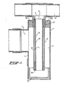
- Fig. 2 shows a preferred embodiment.
- the outer tube 1 and the inner tube 2 are interconnected by means of partitions 16, thus forming channels 17, so that the heat-exchanging fluid supplied through inlet 7, flows downwards through said channels and is heated by the exchange of heat with the surrounding soil and ground water.
- the partitions 16 are integral with the outer tube 1 and the inner tube 2, but it is also possible to use an inner tube 2 being provided with integral projections forming the partitions when such a pipe is placed into an outer tube 1.
- the channels 17 are effectively rounded and preferably have a circular cross-section.
- the free cross-section 13 of the inner tube 2 is preferably dimensioned in such a way that, after absorbing heat in the channels 17, the heat-exchanging fluid flows to the outlet 9 in a laminar flow.
- a T-piece is used having a separate outlet conduit 18, forming the outlet 9, and a separate conduit 19 providing the inlet 7.
- a closing means 21 cooperates with a tube 20 communicating with the outlet 9.
- Fig. 3 shows the same form of construction as is shown in Fig. 2, in this case a foam plastics layer 4 being provided, however, on the inner side of the inner tube 2.
- This foam plastics layer is covered by another inner tube 22 of polyethylene (inner diameter 16 mm and outer diameter 20 mm) being integral with the tube 20 and connected to the inlet 7.
- the foam as used is reticulated polyethylene foam.
- inlet 7 communicates with the inner tube 22 and the outlet 9 communicates with the channels 17.
- This embodiment is, for instance, very suitable for heat recovery, since colder groundwater from which heat has been recovered will, on account of its greater density, accumulate at a lower level and the hotter groundwater will, on account of its lower density, accumulate at a higher level.
- the heat-exchanging fluid will then first come into contact with the colder groundwater and subsequently with the hotter groundwater.
- the inner and outer tubes, which are joined together by the partitions 16 to form an integral pipe advantageously consist of impact-resistant polyvinyl chloride, the diameter of the composite tube being approximately 50 mm.
- annular spaces As far as the foregoing refers to annular spaces, it is obvious that said spaces also comprise spaces whose cross-sections are not circular, but rounded, angular or formed in any other manner.
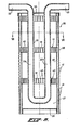
- Fig. 6 shows a pipe 31 in the form of a U-tube provided with an inlet 32 and an outlet 33.
- a heat-exchanging fluid in the form of water, to which antifreeze agents having been added, is supplied to the pipe 31 through the inlet 32 and is carried off through the outlet 33. After heat delivery, the heat-exchanging fluid carried off through the outlet 33 can be carried back to the inlet 32 and so be used again for heat absorption.
- the descending part of the pipe is indicated by 31a, the ascending part by 31b.
- the pip;7 is secured in the top side 34 of a casing 35 surrounding the pipe.
- the bottom side of the casing 35 is closed off by means of a sieve 36 the casing 35 being driven into the soil in such a manner that soil particles cannot pass into the interior of the casing 35 through the sieve bottom 36.
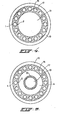
- the casing 35 consists of an outer casing tube 38 and an inner casing tube 39 which are interconnected by means of casing partitions 40, thereby forming first longitudinal casing channels 51. On their outer side said longitudinal casing channels are provided with transverse grooves 41.
- Said grooves 41 afford surrounding groundwater to penetrate therethrough into the longitudinal casing channels 51, while, since said longitudinal casing channels 51 have a small inner diameter, the groundwater penetrating into the longitudinal casing channels 51 will be subject to capilary action therein, thus causing the water to rise in the channels 51.
- Fig. 8 shows a modified embodiment of a device according to Fig. 1, the casing 35 being formed in the same manner as in Fig. 6.
- the reference numerals in said Fig. 8 being denoted in the same manner as in Fig. 6.
- the bottom side of the pipe 44 is closed by means of a sealingly closing cover 46, leaving an annular opening 43, however, which ensures communication between other longitudinal channels 51a, and the interior 45 of the pipe 44.
- the heat-exchanging fluid is carried off through outlet 49 provided in the T-piece 48; the intake proceeds through inlet 47, so that the heat-exchanging fluid engages at the end groundwater having the highest temperature.
- Said inlet 47 is connected to a polyethylene pipe 50(outer diameter 20 mm and inner diameter 16 mm) located in the interior of pipe 44.
- Said pipe 44 comprising an inner wall 44b and an outer wall 44a as well as partitions 44c is used for the transport of the heat-exchanging fluid, said heat-exchanging fluid flowing through the longitudinal channels 51a.
- Sealing rings 53, 53a are provided for holding the polyethylene pipe 50.
- groundwater accumulating in the interior 37 of the porous casing 35 will acquire a greater density after releasing heat and so will flow from the casing, and will be replaced by hotter groundwater.
- This circulation can be appropriately improved by increasing the porosity of the surrounding soil.
- By choosing for example gravel 54 as a filler it is possible to control the porosity as desired around the casing 35.
- the porosity of the soil 58 around said filler can be improved, if desired, by subjecting the casing 35 to a strong vacuum pressure during a certain time, i.e. before putting the tubes 31a, 31b, and 44a, 44b, respectively, into place.
- the casing may also consist of a single-walled tube 55 provided with grooves 56 or other openings; said single-walled tube is then closed off by a closed end cap 57.
- groundwater level is indicated by 59; this groundwater level lies for example 80 cm below the surface 60.
Landscapes
- Engineering & Computer Science (AREA)
- Life Sciences & Earth Sciences (AREA)
- General Life Sciences & Earth Sciences (AREA)
- Sustainable Development (AREA)
- Sustainable Energy (AREA)
- Chemical & Material Sciences (AREA)
- Combustion & Propulsion (AREA)
- Mechanical Engineering (AREA)
- General Engineering & Computer Science (AREA)
- Heat-Exchange Devices With Radiators And Conduit Assemblies (AREA)
Applications Claiming Priority (4)
| Application Number | Priority Date | Filing Date | Title |
|---|---|---|---|
| NL8004513 | 1980-08-07 | ||
| NLAANVRAGE8004509,A NL174184C (nl) | 1980-08-07 | 1980-08-07 | Inrichting voor het onttrekken van warmte aan de bodem. |
| NL8004509 | 1980-08-07 | ||
| NL8004513A NL8004513A (nl) | 1980-08-07 | 1980-08-07 | Inrichting voor het onttrekken van warmte aan de bodem. |
Publications (1)
| Publication Number | Publication Date |
|---|---|
| EP0045993A1 true EP0045993A1 (en) | 1982-02-17 |
Family
ID=26645646
Family Applications (1)
| Application Number | Title | Priority Date | Filing Date |
|---|---|---|---|
| EP81200883A Withdrawn EP0045993A1 (en) | 1980-08-07 | 1981-08-05 | A device and a method for recovering heat from the soil |
Country Status (3)
| Country | Link |
|---|---|
| US (1) | US4452303A (da) |
| EP (1) | EP0045993A1 (da) |
| DK (1) | DK351781A (da) |
Cited By (12)
| Publication number | Priority date | Publication date | Assignee | Title |
|---|---|---|---|---|
| EP0123498A3 (en) * | 1983-04-18 | 1986-04-09 | Megatech Corporation | Wavy tube heat pumping |
| WO1990000707A1 (de) * | 1988-07-08 | 1990-01-25 | Hans Hildebrand | Anlage zum austausch von energie zwischen erdreich und einem energieaustauscher |
| EP0457416A1 (de) * | 1990-05-18 | 1991-11-21 | Diego Horten | Vorrichtung zur Nutzbarmachung von geothermischer Energie |
| CH686736A5 (de) * | 1993-04-21 | 1996-06-14 | Grundag Ag Gossau | Vorrichtung zum Einfuehren einer Erdsonde in ein Bohrloch. |
| EP0916913A3 (de) * | 1997-11-14 | 2000-05-31 | ELIN EBG Elektrotechnik GmbH | Verfahren und Vorrichtung zur Erzeugung von nutzbarer Wärmeenergie |
| WO2012114297A3 (en) * | 2011-02-25 | 2012-11-22 | Bonfiglio Sergio | System for extracting heat from hot rocks and geothermal plant |
| ITTV20120217A1 (it) * | 2012-11-14 | 2014-05-15 | Paolo Sivieri | Sonda geotermica e relativo metodo di funzionamento |
| WO2014088506A1 (en) * | 2012-12-06 | 2014-06-12 | Laplast Ab | Coaxial borehole heat exchanger and method of producing the same |
| WO2020117946A1 (en) * | 2018-12-04 | 2020-06-11 | Regents Of The University Of Minnesota | Groundwater enhanced geothermal heat pump |
| EP3580502A4 (en) * | 2017-02-10 | 2020-12-23 | Her Majesty the Queen in Right of Canada as represented by the Minister of Natural Resources | MULTI-CHANNEL FLOOR HEAT EXCHANGE UNIT AND GEOTHERMAL SYSTEM |
| US12305467B2 (en) | 2020-09-29 | 2025-05-20 | Darcy Solutions, Inc. | Spool-type pitless adapter for groundwater heat exchanger |
| US12422169B2 (en) | 2020-08-28 | 2025-09-23 | Darcy Solutions, Inc. | Groundwater heat exchanger |
Families Citing this family (25)
| Publication number | Priority date | Publication date | Assignee | Title |
|---|---|---|---|---|
| HU193647B (en) * | 1983-02-14 | 1987-11-30 | Melyepitesi Tervezo Vallalat | Method and apparatus for utilizing geothermic energy |
| US4662105A (en) * | 1984-06-15 | 1987-05-05 | Lagow Herman E | Thermal reed design for controlling the temperature of plants |
| US4741388A (en) * | 1984-12-20 | 1988-05-03 | Kazuo Kuroiwa | Underground heat exchanging apparatus |
| US5178485A (en) * | 1988-08-08 | 1993-01-12 | Nihon Chikasui Kaihatsu Kabushiki Kaisha | Heat exchanging pipe system for uniformly heating road surfaces and the like |
| JPH0247403A (ja) * | 1988-08-08 | 1990-02-16 | Nippon Chikasui Kaihatsu Kk | 地下深部の帯水層の保温効果を利用した無散水消雪方法 |
| JPH0247404A (ja) * | 1988-08-08 | 1990-02-16 | Nippon Chikasui Kaihatsu Kk | 井戸内熱交換無散水消雪方法及び装置 |
| SE9400253L (sv) * | 1994-01-27 | 1995-07-28 | Siemens Elema Ab | Anordning avsedd att minska den relativa fuktigheten i en strömmande gas |
| CH689064A5 (de) * | 1994-05-06 | 1998-08-31 | Geohil Ag | Anlage zum Austausch von Energie zwischen Erdreich und einem Energietauscher. |
| US5738164A (en) * | 1996-11-15 | 1998-04-14 | Geohil Ag | Arrangement for effecting an energy exchange between earth soil and an energy exchanger |
| US5937934A (en) * | 1996-11-15 | 1999-08-17 | Geohil Ag | Soil heat exchanger |
| US20050268605A1 (en) * | 2004-06-02 | 2005-12-08 | Wood James G | Method and apparatus for forming a heat exchanger |
| US7363769B2 (en) * | 2005-03-09 | 2008-04-29 | Kelix Heat Transfer Systems, Llc | Electromagnetic signal transmission/reception tower and accompanying base station employing system of coaxial-flow heat exchanging structures installed in well bores to thermally control the environment housing electronic equipment within the base station |
| US7347059B2 (en) * | 2005-03-09 | 2008-03-25 | Kelix Heat Transfer Systems, Llc | Coaxial-flow heat transfer system employing a coaxial-flow heat transfer structure having a helically-arranged fin structure disposed along an outer flow channel for constantly rotating an aqueous-based heat transfer fluid flowing therewithin so as to improve heat transfer with geological environments |
| FR2884905B1 (fr) * | 2005-04-21 | 2007-07-20 | Hades Soc Par Actions Simplifi | Sonde de captage de l'energie thermique du sol pour pompe a chaleur |
| WO2007136775A2 (en) * | 2006-05-19 | 2007-11-29 | Superconductor Technologies Inc. | Heat exchanger assembly |
| EP1978314A1 (en) * | 2007-04-03 | 2008-10-08 | Iride S.r.l. | Geothermal probe |
| EP2198208A1 (de) * | 2007-09-28 | 2010-06-23 | Geo-en Energy Technologies Gmbh | Grundwasserbrunnen |
| EP2179230B1 (de) * | 2007-09-28 | 2014-08-06 | Geo-en Energy Technologies Gmbh | Brunnen zur gewinnung von energie |
| DE202007017371U1 (de) * | 2007-12-11 | 2009-04-16 | Rehau Ag + Co | Erdwärmesonde aus vernetztem Polymermaterial |
| US9103603B2 (en) * | 2009-10-28 | 2015-08-11 | Tai-Her Yang | Thermal conductive cylinder installed with U-type core piping and loop piping |
| US20110203765A1 (en) * | 2010-02-23 | 2011-08-25 | Robert Jensen | Multipipe conduit for geothermal heating and cooling systems |
| US8875778B2 (en) * | 2010-11-15 | 2014-11-04 | Thermodynamique Solutions Inc. | Geothermal adiabatic-isothermal heat sink exchange system |
| US9811126B2 (en) | 2011-10-04 | 2017-11-07 | International Business Machines Corporation | Energy efficient data center liquid cooling with geothermal enhancement |
| CN111322776A (zh) * | 2020-01-03 | 2020-06-23 | 天津大学 | 一种同轴组合套管式换热器 |
| CN116379626B (zh) * | 2023-03-29 | 2026-04-21 | 东南大学 | 一种加速地下水渗流的高效套管式地埋管换热器 |
Citations (13)
| Publication number | Priority date | Publication date | Assignee | Title |
|---|---|---|---|---|
| DE313257C (da) * | 1900-01-01 | |||
| FR1403800A (fr) * | 1964-05-13 | 1965-06-25 | Creusot Forges Ateliers | Dispositif d'assemblage de tubes de forage |
| US3470943A (en) * | 1967-04-21 | 1969-10-07 | Allen T Van Huisen | Geothermal exchange system |
| DE2458457A1 (de) * | 1974-01-11 | 1975-07-17 | Agostino Capello | Verfahren und anlage zur ausbeutung geothermischer energie |
| DE2433890A1 (de) * | 1974-07-15 | 1976-02-05 | Max Dr Boetzkes | Verfahren und vorrichtung zur nutzbarmachung der erdwaerme in tiefen erdschichten |
| US3938592A (en) * | 1970-03-23 | 1976-02-17 | Ivan Timofeevich Aladiev | Rock-exploitation method based on thermodynamic cycles utilizing in-situ energy source |
| US4042012A (en) * | 1976-08-27 | 1977-08-16 | Electric Power Research Institute | Heat pump system with improved heat transfer |
| US4068476A (en) * | 1973-11-15 | 1978-01-17 | Andrew Graham Brown | Solar driven power unit |
| FR2369508A1 (fr) * | 1976-11-01 | 1978-05-26 | Ove Bertil | Procede pour le stockage de chaleur dans le sol, notamment de chaleur solaire |
| US4094356A (en) * | 1977-01-06 | 1978-06-13 | Whewell Frank Ash | Geothermal heat recovery system |
| LU81670A1 (de) * | 1979-09-10 | 1980-01-24 | Feist Artus | Verfahren zur erdwaermegewinnung und vorrichtung zur durchfuehrung dieses verfahrens |
| DE2837169A1 (de) * | 1978-08-25 | 1980-03-06 | Philipp Rauth | Vorrichtung mit raumverdraengungsblock und mit 2 heizkammersystem, hoch- und niedertemperaturheizkammer, zum konstanten energieentzug aus trockenen und heissen gesteinsmassen, bei geringen teufen im erdinnern |
| FR2441840A1 (fr) * | 1978-11-14 | 1980-06-13 | Vicha | Dispositif et procede pour tester un forage d'une installation geothermique |
Family Cites Families (10)
| Publication number | Priority date | Publication date | Assignee | Title |
|---|---|---|---|---|
| US1981730A (en) * | 1933-06-12 | 1934-11-20 | Hawkins Edmund Francis | Water cooler |
| US2665556A (en) * | 1951-02-03 | 1954-01-12 | Griscom Russell Co | Insulated bayonet tube vaporizer |
| FR1059847A (fr) * | 1952-02-29 | 1954-03-29 | Leer S Vatenfabrieken N V Van | Raccord d'écoulement perfectionné pour récipients |
| US2712223A (en) * | 1952-03-31 | 1955-07-05 | Charles D A Hunt | Cyclotron target box cooler |
| US2730083A (en) * | 1953-07-31 | 1956-01-10 | Kremser Johann | Heat exchanger for varying the lubricating oil temperature in internal-combustion engines |
| US3976129A (en) * | 1972-08-17 | 1976-08-24 | Silver Marcus M | Spiral concentric-tube heat exchanger |
| US3991822A (en) * | 1973-03-22 | 1976-11-16 | Olin Corporation | Metal tube having internal passages therein |
| US4030549A (en) * | 1976-01-26 | 1977-06-21 | Cities Service Company | Recovery of geothermal energy |
| FR2357721A1 (fr) * | 1976-07-09 | 1978-02-03 | Vignal Maurice | Procede de preparation d'un trou fore dans le sol pour constituer un echangeur geothermique pour les installations de chauffage |
| US4286651A (en) * | 1980-04-28 | 1981-09-01 | Environmental Impact Research Group | Geothermal heating system and method of installing the same |
-
1981
- 1981-08-04 US US06/289,900 patent/US4452303A/en not_active Expired - Fee Related
- 1981-08-05 EP EP81200883A patent/EP0045993A1/en not_active Withdrawn
- 1981-08-07 DK DK351781A patent/DK351781A/da not_active Application Discontinuation
Patent Citations (13)
| Publication number | Priority date | Publication date | Assignee | Title |
|---|---|---|---|---|
| DE313257C (da) * | 1900-01-01 | |||
| FR1403800A (fr) * | 1964-05-13 | 1965-06-25 | Creusot Forges Ateliers | Dispositif d'assemblage de tubes de forage |
| US3470943A (en) * | 1967-04-21 | 1969-10-07 | Allen T Van Huisen | Geothermal exchange system |
| US3938592A (en) * | 1970-03-23 | 1976-02-17 | Ivan Timofeevich Aladiev | Rock-exploitation method based on thermodynamic cycles utilizing in-situ energy source |
| US4068476A (en) * | 1973-11-15 | 1978-01-17 | Andrew Graham Brown | Solar driven power unit |
| DE2458457A1 (de) * | 1974-01-11 | 1975-07-17 | Agostino Capello | Verfahren und anlage zur ausbeutung geothermischer energie |
| DE2433890A1 (de) * | 1974-07-15 | 1976-02-05 | Max Dr Boetzkes | Verfahren und vorrichtung zur nutzbarmachung der erdwaerme in tiefen erdschichten |
| US4042012A (en) * | 1976-08-27 | 1977-08-16 | Electric Power Research Institute | Heat pump system with improved heat transfer |
| FR2369508A1 (fr) * | 1976-11-01 | 1978-05-26 | Ove Bertil | Procede pour le stockage de chaleur dans le sol, notamment de chaleur solaire |
| US4094356A (en) * | 1977-01-06 | 1978-06-13 | Whewell Frank Ash | Geothermal heat recovery system |
| DE2837169A1 (de) * | 1978-08-25 | 1980-03-06 | Philipp Rauth | Vorrichtung mit raumverdraengungsblock und mit 2 heizkammersystem, hoch- und niedertemperaturheizkammer, zum konstanten energieentzug aus trockenen und heissen gesteinsmassen, bei geringen teufen im erdinnern |
| FR2441840A1 (fr) * | 1978-11-14 | 1980-06-13 | Vicha | Dispositif et procede pour tester un forage d'une installation geothermique |
| LU81670A1 (de) * | 1979-09-10 | 1980-01-24 | Feist Artus | Verfahren zur erdwaermegewinnung und vorrichtung zur durchfuehrung dieses verfahrens |
Cited By (19)
| Publication number | Priority date | Publication date | Assignee | Title |
|---|---|---|---|---|
| EP0123498A3 (en) * | 1983-04-18 | 1986-04-09 | Megatech Corporation | Wavy tube heat pumping |
| WO1990000707A1 (de) * | 1988-07-08 | 1990-01-25 | Hans Hildebrand | Anlage zum austausch von energie zwischen erdreich und einem energieaustauscher |
| US5322115A (en) * | 1988-07-08 | 1994-06-21 | Hans Hildebrand | Installation for energy exchange between the ground and an energy exchanger |
| EP0457416A1 (de) * | 1990-05-18 | 1991-11-21 | Diego Horten | Vorrichtung zur Nutzbarmachung von geothermischer Energie |
| WO1991018205A1 (de) * | 1990-05-18 | 1991-11-28 | Diego Horten | Vorrichtung zur nutzbarmachung von geothermischer energie |
| US5203173A (en) * | 1990-05-18 | 1993-04-20 | Diego Horton | Device for utilization of geothermal energy |
| CH686736A5 (de) * | 1993-04-21 | 1996-06-14 | Grundag Ag Gossau | Vorrichtung zum Einfuehren einer Erdsonde in ein Bohrloch. |
| EP0916913A3 (de) * | 1997-11-14 | 2000-05-31 | ELIN EBG Elektrotechnik GmbH | Verfahren und Vorrichtung zur Erzeugung von nutzbarer Wärmeenergie |
| WO2012114297A3 (en) * | 2011-02-25 | 2012-11-22 | Bonfiglio Sergio | System for extracting heat from hot rocks and geothermal plant |
| ITTV20120217A1 (it) * | 2012-11-14 | 2014-05-15 | Paolo Sivieri | Sonda geotermica e relativo metodo di funzionamento |
| WO2014088506A1 (en) * | 2012-12-06 | 2014-06-12 | Laplast Ab | Coaxial borehole heat exchanger and method of producing the same |
| CN104919257A (zh) * | 2012-12-06 | 2015-09-16 | 三管地热公司 | 同轴地埋管换热器及其制造方法 |
| US10001300B2 (en) | 2012-12-06 | 2018-06-19 | Triopipe Geotherm Ab | Coaxial borehole heat exchanger and method of producing the same |
| EP3580502A4 (en) * | 2017-02-10 | 2020-12-23 | Her Majesty the Queen in Right of Canada as represented by the Minister of Natural Resources | MULTI-CHANNEL FLOOR HEAT EXCHANGE UNIT AND GEOTHERMAL SYSTEM |
| US11181302B2 (en) | 2017-02-10 | 2021-11-23 | Her Majesty The Queen In Right Of Canada As Represented By The Minister Of Natural Resources Canada | Multi-channel ground heat exchange unit and geothermal system |
| WO2020117946A1 (en) * | 2018-12-04 | 2020-06-11 | Regents Of The University Of Minnesota | Groundwater enhanced geothermal heat pump |
| US12553645B2 (en) | 2018-12-04 | 2026-02-17 | Regents Of The University Of Minnesota | Groundwater enhanced geothermal heat pump |
| US12422169B2 (en) | 2020-08-28 | 2025-09-23 | Darcy Solutions, Inc. | Groundwater heat exchanger |
| US12305467B2 (en) | 2020-09-29 | 2025-05-20 | Darcy Solutions, Inc. | Spool-type pitless adapter for groundwater heat exchanger |
Also Published As
| Publication number | Publication date |
|---|---|
| DK351781A (da) | 1982-02-08 |
| US4452303A (en) | 1984-06-05 |
Similar Documents
| Publication | Publication Date | Title |
|---|---|---|
| EP0045993A1 (en) | A device and a method for recovering heat from the soil | |
| US4574875A (en) | Heat exchanger for geothermal heating and cooling systems | |
| CN201866970U (zh) | 同层地热循环利用系统 | |
| KR100997184B1 (ko) | 블리딩 지하수를 재활용하는 개방형 지열시스템장치 | |
| KR101792145B1 (ko) | 공내 열교환기를 구성한 지열 시스템 | |
| KR101598562B1 (ko) | 지열을 이용한 냉난방 시스템의 열원을 획득하기 위한 지중열교환장치 | |
| KR101591017B1 (ko) | 지하대수층의 깊이 차이를 이용한 축열 냉난방 시스템 | |
| CN113639304A (zh) | 一种强制对流换热型地热水平井单井供热系统 | |
| KR20100062755A (ko) | 지하수의 열을 이용한 수막시설 냉난방 시스템 | |
| CN110397466B (zh) | 一种矿井工作面降温系统 | |
| JPS5917340B2 (ja) | 土から熱を回収する装置 | |
| JP2021131223A (ja) | 地中熱利用装置及び該地中熱利用装置の使用方法 | |
| EP0073836A1 (en) | Latent heat accumulating greenhouses | |
| JP2003307089A (ja) | 孔内を分割した地中熱採熱孔 | |
| KR200436894Y1 (ko) | 지열 및 지하수 공급장치 | |
| JPH06228928A (ja) | 冷却還元液を蘇生・融雪地熱液とする循環地中装置 | |
| KR100803351B1 (ko) | 지열에너지 이용을 위한 지중 열교환 시스템 | |
| RU2057912C1 (ru) | Способ разработки нефтяного месторождения | |
| RU2117113C1 (ru) | Способ получения пресной воды | |
| CN107096354A (zh) | 污泥干化载气系统 | |
| JP6303361B2 (ja) | 採熱井及び融雪方法 | |
| JPS61186757A (ja) | 地熱利用融雪方法及びその装置 | |
| JPS6320913Y2 (da) | ||
| JPS62223568A (ja) | 井戸装置 | |
| JP3040018U (ja) | 地下水排水管 |
Legal Events
| Date | Code | Title | Description |
|---|---|---|---|
| PUAI | Public reference made under article 153(3) epc to a published international application that has entered the european phase |
Free format text: ORIGINAL CODE: 0009012 |
|
| AK | Designated contracting states |
Designated state(s): AT BE CH DE FR GB IT LI LU NL SE |
|
| 17P | Request for examination filed |
Effective date: 19811231 |
|
| STAA | Information on the status of an ep patent application or granted ep patent |
Free format text: STATUS: THE APPLICATION IS DEEMED TO BE WITHDRAWN |
|
| 18D | Application deemed to be withdrawn |
Effective date: 19830831 |
|
| RIN1 | Information on inventor provided before grant (corrected) |
Inventor name: BONTJE, THEODORUS PETRUS MARIA Inventor name: SCHULDINK, GERRIT Inventor name: DE PUTTER, WARNER JAN Inventor name: HEETBRINK, GERRIT HENDRIK Inventor name: KOK, BERNARDUS HENRICUS |