EP0045269B1 - Suspension oléopneumatique - Google Patents
Suspension oléopneumatique Download PDFInfo
- Publication number
- EP0045269B1 EP0045269B1 EP81401221A EP81401221A EP0045269B1 EP 0045269 B1 EP0045269 B1 EP 0045269B1 EP 81401221 A EP81401221 A EP 81401221A EP 81401221 A EP81401221 A EP 81401221A EP 0045269 B1 EP0045269 B1 EP 0045269B1
- Authority
- EP
- European Patent Office
- Prior art keywords
- fact
- volume
- suspension according
- chambers
- fluid
- Prior art date
- Legal status (The legal status is an assumption and is not a legal conclusion. Google has not performed a legal analysis and makes no representation as to the accuracy of the status listed.)
- Expired
Links
- 239000000725 suspension Substances 0.000 title claims description 34
- 239000012530 fluid Substances 0.000 claims description 48
- 238000005096 rolling process Methods 0.000 claims description 26
- 238000013016 damping Methods 0.000 claims description 25
- 238000001816 cooling Methods 0.000 claims description 4
- 238000006073 displacement reaction Methods 0.000 claims description 4
- 238000000926 separation method Methods 0.000 claims 2
- 239000007787 solid Substances 0.000 claims 1
- 230000007423 decrease Effects 0.000 description 6
- 238000005192 partition Methods 0.000 description 4
- 230000035939 shock Effects 0.000 description 4
- 230000006835 compression Effects 0.000 description 3
- 238000007906 compression Methods 0.000 description 3
- 238000004519 manufacturing process Methods 0.000 description 3
- IJGRMHOSHXDMSA-UHFFFAOYSA-N Atomic nitrogen Chemical compound N#N IJGRMHOSHXDMSA-UHFFFAOYSA-N 0.000 description 2
- 239000006096 absorbing agent Substances 0.000 description 2
- 230000000694 effects Effects 0.000 description 2
- 239000007789 gas Substances 0.000 description 2
- 238000012423 maintenance Methods 0.000 description 2
- 239000000463 material Substances 0.000 description 2
- 229910001018 Cast iron Inorganic materials 0.000 description 1
- 241000287107 Passer Species 0.000 description 1
- XAGFODPZIPBFFR-UHFFFAOYSA-N aluminium Chemical compound [Al] XAGFODPZIPBFFR-UHFFFAOYSA-N 0.000 description 1
- 229910052782 aluminium Inorganic materials 0.000 description 1
- 230000003042 antagnostic effect Effects 0.000 description 1
- 230000000712 assembly Effects 0.000 description 1
- 238000000429 assembly Methods 0.000 description 1
- 230000005540 biological transmission Effects 0.000 description 1
- 238000010276 construction Methods 0.000 description 1
- 238000010586 diagram Methods 0.000 description 1
- 238000009826 distribution Methods 0.000 description 1
- 235000021183 entrée Nutrition 0.000 description 1
- 230000017525 heat dissipation Effects 0.000 description 1
- 238000010438 heat treatment Methods 0.000 description 1
- 238000010030 laminating Methods 0.000 description 1
- 238000005461 lubrication Methods 0.000 description 1
- 229910052757 nitrogen Inorganic materials 0.000 description 1
- 230000003252 repetitive effect Effects 0.000 description 1
- 230000009466 transformation Effects 0.000 description 1
Images
Classifications
-
- F—MECHANICAL ENGINEERING; LIGHTING; HEATING; WEAPONS; BLASTING
- F16—ENGINEERING ELEMENTS AND UNITS; GENERAL MEASURES FOR PRODUCING AND MAINTAINING EFFECTIVE FUNCTIONING OF MACHINES OR INSTALLATIONS; THERMAL INSULATION IN GENERAL
- F16F—SPRINGS; SHOCK-ABSORBERS; MEANS FOR DAMPING VIBRATION
- F16F9/00—Springs, vibration-dampers, shock-absorbers, or similarly-constructed movement-dampers using a fluid or the equivalent as damping medium
- F16F9/32—Details
- F16F9/42—Cooling arrangements
-
- B—PERFORMING OPERATIONS; TRANSPORTING
- B60—VEHICLES IN GENERAL
- B60G—VEHICLE SUSPENSION ARRANGEMENTS
- B60G15/00—Resilient suspensions characterised by arrangement, location or type of combined spring and vibration damper, e.g. telescopic type
- B60G15/08—Resilient suspensions characterised by arrangement, location or type of combined spring and vibration damper, e.g. telescopic type having fluid spring
- B60G15/12—Resilient suspensions characterised by arrangement, location or type of combined spring and vibration damper, e.g. telescopic type having fluid spring and fluid damper
-
- B—PERFORMING OPERATIONS; TRANSPORTING
- B62—LAND VEHICLES FOR TRAVELLING OTHERWISE THAN ON RAILS
- B62D—MOTOR VEHICLES; TRAILERS
- B62D55/00—Endless track vehicles
- B62D55/08—Endless track units; Parts thereof
- B62D55/104—Suspension devices for wheels, rollers, bogies or frames
- B62D55/112—Suspension devices for wheels, rollers, bogies or frames with fluid springs, e.g. hydraulic pneumatic
- B62D55/1125—Hydro-pneumatic or pneumatic, e.g. air-cushioned
Definitions
- the present invention relates to oleopneumatic suspensions, more particularly for heavy vehicles and in particular, but not exclusively, for all - terrain vehicles with tracks or wheels.
- shock absorber which generally comprise a fluid spring and means of damping by circulation of incompressible fluid through rolling valves. These devices give good results when they are associated with light vehicles or when they are used only for very short times.
- damping systems are constantly stressed and therefore pose great problems, in particular of heat dissipation obtained by the well-known transformation of mechanical energy into calorific energy. .
- the object of the present invention is to produce an oleopneumatic suspension ensuring the functions of spring and damping in a constant and reliable manner while having maintenance facilities and despite everything retaining a modular structure.
- Document FR-A-1 398 657 discloses a hydraulic damper corresponding to the preamble of claim 1 and in which there are several variable volume hydraulic fluid chambers and a fluid container; the chambers are connected to this fluid container by connection means which establish, as the case may be, a direct connection or a connection through spring-loaded valves.
- connection means which establish, as the case may be, a direct connection or a connection through spring-loaded valves.
- connection means can no longer be modified after construction and these means comprise variously calibrated valves which have different, but non-modifiable, effects of rolling the hydraulic fluid.
- the first means for varying the volume of a first incompressible fluid chamber consist of a first piston sliding in a first housing relative to a first wall of this housing, said first piston being connected to said functional connecting means.
- the second means for varying the volume of a second incompressible fluid chamber consist of a second piston sliding in a second housing relative to a second wall of this housing, said second piston being connected to said functional connection means.
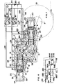
- An oleopneumatic suspension as shown in fig. 1, comprises a main body or casing 1 capable of being fixed to the body or chassis of a vehicle by any means, screw bolts, etc.
- This casing 1 comprises a central cavity 2 into which open in this embodiment two lateral housings 3 and 4 arranged symmetrically with respect to a point 5.
- An axis 6 crosses the wall of the central cavity 2 by means of a sealed passage for support outside of the cavity a lever 7 on which is fixed a rolling means 8 such as for example a wheel, with its tire, or a guide roller of a caterpillar.
- crankshaft 9 On the part of the axis 6 inside the central cavity 2, a crankshaft 9 is fixed, for example by means of a “polygon” assembly as shown or splines, etc.
- This crankshaft assumes the shape of an oblong part symmetrical with respect to point 5 mentioned above.
- the casing 1 has a symmetrical shape and the means which are illustrated in the two lateral housings 3 and 4 are perfectly identical, they will bear as an indication the same references, and as, moreover, their functions are also identical and that their effects only add up, reference will be made thereafter for the explanation only to the part of the oleopneumatic damper essentially comprising the crankshaft and all the elements cooperating directly or indirectly with the lateral housing 3.
- the man of the art can very easily deduce the functions and operation of the means cooperating with the other lateral housing 4.
- the chamber 20 is formed between the bottom 23 of the housing 3, its side wall 25, and the face 26 of the piston 17 of the moving element 14.
- This chamber contains an elastic means such as for example a compressible fluid such as a gas.
- This chamber can be filled through a valve 24 integral with the wall 25 of the housing 3.
- the chamber 21 is defined between the wall 25 of the housing 3, the partition 15, the surface 28 of the rod 19 and the second face 27 of the piston 17.
- this chamber is of annular shape.
- the chamber 22, which is also of annular shape, is formed between the wall 25 of the housing 3, the partition 15, the rod 19 and the face 29 of the piston 18.
- the other face 30 of the piston is turned towards the cavity 2 and constitutes a part of the wall of the cavity 2 tending to make it sealed.
- the chambers 21 are connected by pipes 40 to the inlet 41 of a non-return valve 42, the outlet 43 of which is connected by a pipe 47 to the inlet 44 of a rolling means 45 possibly controllable at will .
- the outlet 46 of this rolling means 45 is connected by a pipe 48 to the cavity 2 defined above, this pipe opens into the cavity 2 at a location 69 which is located in the cavity so that it is a high point in depending on the location of the oil-pneumatic suspension on the vehicle.
- the pipes 40 are also connected to the outlet 49 of a non-return valve 50, the inlet 51 of which is connected by a pipe 52 to the cavity 2 at a point 53 which constitutes a low point relative to the point 69 .
- the chambers 22 are connected by pipes 54 to the inlet 55 of a non-return valve 56, the outlet 57 of which is connected, to the inlet 44 of the rolling means 45 mentioned previously, by a pipe 58.
- the pipe 54 is also connected to the outlet 59 of a non-return valve 60 whose inlet 61 is connected to the pipe 52 to connect this inlet 61 to the low point 53 of the cavity 2.
- the cavity 2 defined by the casing 1 and the two faces 30 of the two pistons 18 is sealed.
- the chambers 21 and 22, the pipes from these chambers to the cavity 2 must be perfectly filled with an incompressible fluid such as oil while the cavity 2 must contain fluid in its lower part 70 to cover in all circumstances the low point 53, but leave in the upper part 71, above the average level 72 of the oil, a volume of pressurized gas such as for example nitrogen, so that level 72 is normally located below the high point 69.
- the incompressible fluid is expelled from this chamber and through the lines 54 is sent into the rolling means 45 through the non-return valve 56 since the valve 60 cannot be traversed by the fluid when it comes from the chambers 22.
- the fluid flows into the cavity 2 through the pipe 48.
- the fluid is expelled through the pipes 40 and passes through the non-return valve 42 and the rolling means 45 before flowing into the cavity 2, but, on the other hand, fluid is drawn into the cavity 2 by the pipe 52 and compensates for the increase in volume of the chambers 22 by having passed through the non-return valve 60 and passed through the pipes 54.
- the chambers 20 containing elastic fluid act as a spring and a means for bringing back to the equilibrium position all of the mobile elements of the oleopneumatic suspension and consequently the lever 7 and the wheel 8.
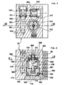
- FIGS. 2 and 3 An embodiment of the block 75 is illustrated in FIGS. 2 and 3 representing two perpendicular sections.
- Fig. 2 shows a section along II-II of FIG. 3 and fig. 3 a section along III-III of FIG. 2.
- the block 75 is therefore made of a material having a relatively good thermal conductivity such as, for example, cast iron or aluminum, and comprises, on at least one of its faces, cooling fins 76.
- FIGS. 1, 2 and 3 use the same functional elements, and this is how the two non-return valves 42 and 50 correspond to the valves 142 and 150; a portion of the pipe 40 at the orifice 140; line 47 to line portion 147; the entry of the rolling means 44 at the annular orifice 144; the rolling means 45 to the means 145; line 46 to port 146 etc.
- the block 75 comprises two perpendicular channels 141 and 151 which enclose the two valves 150 and 142, the valve 150 being located in the axis of the channel 151 and the valve 142 in the axis of the channel 141.
- these valves consist of cylindrical parts having a longitudinal hollow housing closed at one of its ends to form the cooperating part with a seat, and a radial through orifice to allow for example to communicate the inlet. 140 with line 147.
- valves cooperate with seats 163 and 164 machined or attached as in fig.v2.
- valves 156 and 160 corresponding to the functional valves 56 and 60 of FIG. 1 are identical to the valves 142 and 150 but are situated in a plane which would be in front with respect to that of FIG. 2.
- valves 142 and 156 communicate by their outputs by means of the conduit 147 with a housing 192 in which the rolling means 145 are arranged with their control means.
- the bottom 172 of the jacket 165 traps a piston 173, supporting a stop 193, slidably mounted in a bore 195 of the bottom 172 made in the axis of the damping valve 186, so that the stop can cooperate with a corresponding stop 194 integral with the valve 186.
- the bore 195 is connected to an inlet 184 by means of a circular groove 180, holes 181, another annular groove 182 and a groove 183 formed in the bottom 172.
- the autonomous damping block 75 operates as follows. This operation will be explained in a single case, that where the chambers 21 decrease in volume, while the chambers 22 increase in volume.
- the fluid or oil discharged from the chambers 21 maintains, arriving through the orifices 140, the non-return valve 150 against its seat 163 which is then closed, but on the other hand, pushes the valve 142 and enters through the orifice 144 in the cavity 192 above and around the shirt 165.
- This oil can only come out of this cavity 192 by pushing the damping valve 186 so that it discovers a certain number of orifices 170. This movement of the valve 186 takes place against the springs 185 which also compress and balance the pressure in the cavity 192.
- the fluid is aspirated as described above.
- FIG. 1 Figs 2 and 3, representing a concrete embodiment of the block 75 shown schematically in fig. 1, highlight its advantages.
- this block has only one set of rolling means, which is relatively complicated in its production while that of the valves is relatively simple. On the other hand, only one identical damping is obtained for compression and expansion.
- Fig. 4 shows in diagrammatic form, another embodiment of the damping block shown at 75 in FIG. 1.
- the pipe 40 (fig. 1) is connected, on the one hand, to the inlet 444 of first rolling means 445, the outlet 446 of which is connected to the pipe 48 (fig. 1) and, on the other hand, at the outlet 449 of a non-return valve 450, the inlet 451 of which is connected to the pipe 52 (FIG. 1).
- the pipe 54 is connected, on the one hand, to the inlet 544 of second rolling means 545, the outlet 546 of which is connected to the pipe 48 (fig. 1) and, on the other hand, to the outlet 459 of a non-return valve 460 whose inlet 461 is connected to the pipe 52 (fig. 1).
- the advantage of the device according to FIG. 4 is that it allows possible adjustment separate from the first and second rolling means to obtain different dampings, for example in expansion and compression.
- valves 450 and 460 as well as the first and second controllable rolling means 445 and 545 can be identical in their embodiment to those shown in section in FIGS 2 and 3, arranged in the same autonomous block , the production of this block does not present any difficulties for those skilled in the art knowing the diagram according to FIG. 4 and the embodiments according to figs 2 and 3.
- the oil discharged passes through the controllable rolling means 545 to return to the cavity 2, while the oil sucked passes through the valve 450 coming from the pipe 52 and cannot pass through the valve 460 due to the pressure oppositions.
- the lines 40, 54, 48 and 52 will advantageously be integrated in the casing 1, which gives this suspension a modular design facilitating maintenance and adjustments.
- the damping oil may have perfect cooling due to the circulation of the heated oil, contributing to the production of a suspension which can be subjected to very often repetitive loads and for long periods, without showing fatigue and therefore have a very long service life, while having in addition due to the particular configuration of the buffer volume around the transmission axes, connecting rod, etc., in the cavity 2, good lubrication of all these elements.
Landscapes
- Engineering & Computer Science (AREA)
- Mechanical Engineering (AREA)
- General Engineering & Computer Science (AREA)
- Chemical & Material Sciences (AREA)
- Combustion & Propulsion (AREA)
- Transportation (AREA)
- Vehicle Body Suspensions (AREA)
Applications Claiming Priority (2)
| Application Number | Priority Date | Filing Date | Title |
|---|---|---|---|
| FR8016674 | 1980-07-29 | ||
| FR8016674A FR2487737A1 (fr) | 1980-07-29 | 1980-07-29 | Suspension oleopneumatique |
Publications (2)
| Publication Number | Publication Date |
|---|---|
| EP0045269A1 EP0045269A1 (fr) | 1982-02-03 |
| EP0045269B1 true EP0045269B1 (fr) | 1986-06-04 |
Family
ID=9244644
Family Applications (1)
| Application Number | Title | Priority Date | Filing Date |
|---|---|---|---|
| EP81401221A Expired EP0045269B1 (fr) | 1980-07-29 | 1981-07-29 | Suspension oléopneumatique |
Country Status (3)
| Country | Link |
|---|---|
| EP (1) | EP0045269B1 (OSRAM) |
| DE (1) | DE3174766D1 (OSRAM) |
| FR (1) | FR2487737A1 (OSRAM) |
Families Citing this family (5)
| Publication number | Priority date | Publication date | Assignee | Title |
|---|---|---|---|---|
| IT1157402B (it) * | 1982-01-12 | 1987-02-11 | Sebac Ind Spa | Ammortizzatore idro-pneumatico per sospensioni con serbatoio separato, in particolare per motoveicoli |
| FR2556804B1 (fr) * | 1983-12-14 | 1987-01-30 | Applic Mach Motrices | Element de suspension hydropneumatique de vehicule, notamment suspension oleopneumatique destinee a equiper des vehicules lourds, et suspension constituee de tels elements |
| FR2567080B1 (fr) * | 1984-07-09 | 1987-01-09 | Lucas France | Suspension pour vehicule |
| FR2574349B1 (fr) * | 1984-12-12 | 1988-11-10 | Applic Mach Motrices | Element de suspension hydropneumatique d'un vehicule lourd ou du train d'atterrissage d'un aeronef |
| FR2640339B1 (fr) * | 1988-12-09 | 1993-01-22 | Peugeot | Amortisseur hydraulique destine a equiper un organe de suspension, par exemple d'un vehicule automobile |
Citations (5)
| Publication number | Priority date | Publication date | Assignee | Title |
|---|---|---|---|---|
| FR425881A (fr) * | 1911-01-26 | 1911-06-22 | Pestourie & Quentin Soc | Amortisseur pour suspension de véhicules |
| US1500277A (en) * | 1921-07-23 | 1924-07-08 | Selker Harry | Shock absorber |
| US2953367A (en) * | 1958-04-18 | 1960-09-20 | Armstrong Patents Co Ltd | Hydraulic piston and cylinder apparatus |
| DE1455930A1 (de) * | 1965-12-20 | 1969-06-12 | Rheinstahl Henschel Ag | Gleiskettenfahrzeug,insbesondere Panzerkampfwagen |
| FR2313605A1 (fr) * | 1975-06-07 | 1976-12-31 | Rheinstahl Ag | Element elastique hydropneumatique |
Family Cites Families (8)
| Publication number | Priority date | Publication date | Assignee | Title |
|---|---|---|---|---|
| FR956413A (OSRAM) * | 1950-02-01 | |||
| US1797751A (en) * | 1928-11-20 | 1931-03-24 | Gen Motors Res Corp | Shock absorber |
| US3103993A (en) * | 1959-12-09 | 1963-09-17 | Houdaille Industries Inc | Linear hydraulic damper |
| BE634275A (OSRAM) * | 1963-06-28 | |||
| DE1455859A1 (de) * | 1965-02-03 | 1969-11-13 | Rheinstahl Henschel Ag | Stossdaempfer fuer Fahrzeuge |
| US3602470A (en) * | 1969-05-28 | 1971-08-31 | Fmc Corp | Hydropneumatic suspension unit |
| DE2038744A1 (de) * | 1970-08-04 | 1972-02-17 | Liebherr Hans E H Dr Ing | Hydraulische Federung fuer Fahrzeugachsen |
| US3727961A (en) * | 1971-12-13 | 1973-04-17 | Gen Motors Corp | Fluid shock absorbing bumper assembly |
-
1980
- 1980-07-29 FR FR8016674A patent/FR2487737A1/fr active Granted
-
1981
- 1981-07-29 EP EP81401221A patent/EP0045269B1/fr not_active Expired
- 1981-07-29 DE DE8181401221T patent/DE3174766D1/de not_active Expired
Patent Citations (5)
| Publication number | Priority date | Publication date | Assignee | Title |
|---|---|---|---|---|
| FR425881A (fr) * | 1911-01-26 | 1911-06-22 | Pestourie & Quentin Soc | Amortisseur pour suspension de véhicules |
| US1500277A (en) * | 1921-07-23 | 1924-07-08 | Selker Harry | Shock absorber |
| US2953367A (en) * | 1958-04-18 | 1960-09-20 | Armstrong Patents Co Ltd | Hydraulic piston and cylinder apparatus |
| DE1455930A1 (de) * | 1965-12-20 | 1969-06-12 | Rheinstahl Henschel Ag | Gleiskettenfahrzeug,insbesondere Panzerkampfwagen |
| FR2313605A1 (fr) * | 1975-06-07 | 1976-12-31 | Rheinstahl Ag | Element elastique hydropneumatique |
Also Published As
| Publication number | Publication date |
|---|---|
| FR2487737B1 (OSRAM) | 1984-02-10 |
| EP0045269A1 (fr) | 1982-02-03 |
| DE3174766D1 (de) | 1986-07-10 |
| FR2487737A1 (fr) | 1982-02-05 |
Similar Documents
| Publication | Publication Date | Title |
|---|---|---|
| EP0234157B1 (fr) | Amortisseur de rotation | |
| EP0275503B1 (fr) | Amortisseur à compensation de charge | |
| CA2397569C (fr) | Amortisseur a haut pouvoir dissipatif | |
| EP0003290B1 (fr) | Amortisseur hydraulique de suspension de véhicule | |
| EP0461981A2 (fr) | Dispositif ressort-amortisseur à course variable pour véhicule | |
| EP0335786B1 (fr) | Contre-fiche élastique à résonateur hydro-mécanique intégré notamment pour la suspension d'une boîte de transmission sur un giravion, et dispositif de suspension en comportant application | |
| EP2440806B1 (fr) | Amortisseur et atterrisseur equipe d'un tel amortisseur | |
| EP0051506A1 (fr) | Amortisseur-vérin | |
| FR2554415A1 (fr) | Atterrisseurs pour aeronef, notamment pour helicoptere | |
| EP0045269B1 (fr) | Suspension oléopneumatique | |
| EP2614269A1 (fr) | Amortisseur a haut pouvoir dissipatif et pratiquement sans huile | |
| FR2809786A1 (fr) | Amortisseur d'oscillations a chambre annulaire de volume variable | |
| EP0332509B1 (fr) | Amortisseur à étanchéité dynamique améliorée | |
| FR3035351A1 (fr) | Dispositif de suspension pneumatique | |
| EP0186565B1 (fr) | Elément de suspension hydropneumatique d'un véhicule lourd ou du train d'atterrissage d'un aéronef | |
| FR2552514A1 (fr) | Amortisseur du type fluidique | |
| EP0250956A1 (fr) | Dispositif d'amortissement agissant selon les six degrès de liberté | |
| FR2672356A1 (fr) | Dispositif de ressort-amortisseur a course reglable. | |
| EP0168323B1 (fr) | Suspension pour véhicule | |
| FR2479386A1 (fr) | Amortisseur hydraulique sous pression | |
| EP0585189B1 (fr) | Vérin hydraulique hautes performances à contrÔle du jeu | |
| FR2759947A1 (fr) | Suspension de vehicule et valve hydraulique convenant a cette suspension | |
| EP4623222A1 (fr) | Amortisseur hydraulique de suspension de véhicule automobile | |
| EP1978277B1 (fr) | Module de compensation pour un amortisseur hydraulique de véhicule, et amortisseur equipé d'un tel module de compensation | |
| EP1409890A1 (fr) | Amortisseur |
Legal Events
| Date | Code | Title | Description |
|---|---|---|---|
| PUAI | Public reference made under article 153(3) epc to a published international application that has entered the european phase |
Free format text: ORIGINAL CODE: 0009012 |
|
| AK | Designated contracting states |
Designated state(s): DE GB IT |
|
| 17P | Request for examination filed |
Effective date: 19820407 |
|
| ITF | It: translation for a ep patent filed | ||
| GRAA | (expected) grant |
Free format text: ORIGINAL CODE: 0009210 |
|
| RAP1 | Party data changed (applicant data changed or rights of an application transferred) |
Owner name: LUCAS FRANCE S.A. |
|
| AK | Designated contracting states |
Kind code of ref document: B1 Designated state(s): DE GB IT |
|
| REF | Corresponds to: |
Ref document number: 3174766 Country of ref document: DE Date of ref document: 19860710 |
|
| PLBE | No opposition filed within time limit |
Free format text: ORIGINAL CODE: 0009261 |
|
| STAA | Information on the status of an ep patent application or granted ep patent |
Free format text: STATUS: NO OPPOSITION FILED WITHIN TIME LIMIT |
|
| 26N | No opposition filed | ||
| ITTA | It: last paid annual fee | ||
| PGFP | Annual fee paid to national office [announced via postgrant information from national office to epo] |
Ref country code: GB Payment date: 19970722 Year of fee payment: 17 Ref country code: DE Payment date: 19970722 Year of fee payment: 17 |
|
| PG25 | Lapsed in a contracting state [announced via postgrant information from national office to epo] |
Ref country code: GB Free format text: LAPSE BECAUSE OF NON-PAYMENT OF DUE FEES Effective date: 19980729 |
|
| GBPC | Gb: european patent ceased through non-payment of renewal fee |
Effective date: 19980729 |
|
| PG25 | Lapsed in a contracting state [announced via postgrant information from national office to epo] |
Ref country code: DE Free format text: LAPSE BECAUSE OF NON-PAYMENT OF DUE FEES Effective date: 19990501 |