EP0044796A2 - Clamping-sleeve for a parasol - Google Patents
Clamping-sleeve for a parasol Download PDFInfo
- Publication number
- EP0044796A2 EP0044796A2 EP81420107A EP81420107A EP0044796A2 EP 0044796 A2 EP0044796 A2 EP 0044796A2 EP 81420107 A EP81420107 A EP 81420107A EP 81420107 A EP81420107 A EP 81420107A EP 0044796 A2 EP0044796 A2 EP 0044796A2
- Authority
- EP
- European Patent Office
- Prior art keywords
- hole
- ring
- parasol
- mast
- furniture
- Prior art date
- Legal status (The legal status is an assumption and is not a legal conclusion. Google has not performed a legal analysis and makes no representation as to the accuracy of the status listed.)
- Granted
Links
- 239000004020 conductor Substances 0.000 claims description 3
- 230000000903 blocking effect Effects 0.000 description 4
- 230000000694 effects Effects 0.000 description 2
- 230000002349 favourable effect Effects 0.000 description 2
- 239000004952 Polyamide Substances 0.000 description 1
- 230000003100 immobilizing effect Effects 0.000 description 1
- 239000000463 material Substances 0.000 description 1
- 229920002647 polyamide Polymers 0.000 description 1
- 229920003002 synthetic resin Polymers 0.000 description 1
- 239000000057 synthetic resin Substances 0.000 description 1
Images
Classifications
-
- A—HUMAN NECESSITIES
- A47—FURNITURE; DOMESTIC ARTICLES OR APPLIANCES; COFFEE MILLS; SPICE MILLS; SUCTION CLEANERS IN GENERAL
- A47B—TABLES; DESKS; OFFICE FURNITURE; CABINETS; DRAWERS; GENERAL DETAILS OF FURNITURE
- A47B37/00—Tables adapted for other particular purposes
- A47B37/04—Tables specially adapted for use in the garden or otherwise in the open air, e.g. with means for holding umbrellas or umbrella-like sunshades
-
- F—MECHANICAL ENGINEERING; LIGHTING; HEATING; WEAPONS; BLASTING
- F16—ENGINEERING ELEMENTS AND UNITS; GENERAL MEASURES FOR PRODUCING AND MAINTAINING EFFECTIVE FUNCTIONING OF MACHINES OR INSTALLATIONS; THERMAL INSULATION IN GENERAL
- F16B—DEVICES FOR FASTENING OR SECURING CONSTRUCTIONAL ELEMENTS OR MACHINE PARTS TOGETHER, e.g. NAILS, BOLTS, CIRCLIPS, CLAMPS, CLIPS OR WEDGES; JOINTS OR JOINTING
- F16B9/00—Connections of rods or tubular parts to flat surfaces at an angle
- F16B9/05—Connections of rods or tubular parts to flat surfaces at an angle by way of an intermediate member
- F16B9/056—Connections of rods or tubular parts to flat surfaces at an angle by way of an intermediate member the intermediate member extending through the flat surface; the rod or tubular part extending through the flat surface
-
- F—MECHANICAL ENGINEERING; LIGHTING; HEATING; WEAPONS; BLASTING
- F16—ENGINEERING ELEMENTS AND UNITS; GENERAL MEASURES FOR PRODUCING AND MAINTAINING EFFECTIVE FUNCTIONING OF MACHINES OR INSTALLATIONS; THERMAL INSULATION IN GENERAL
- F16B—DEVICES FOR FASTENING OR SECURING CONSTRUCTIONAL ELEMENTS OR MACHINE PARTS TOGETHER, e.g. NAILS, BOLTS, CIRCLIPS, CLAMPS, CLIPS OR WEDGES; JOINTS OR JOINTING
- F16B9/00—Connections of rods or tubular parts to flat surfaces at an angle
- F16B9/05—Connections of rods or tubular parts to flat surfaces at an angle by way of an intermediate member
- F16B9/058—Connections of rods or tubular parts to flat surfaces at an angle by way of an intermediate member the intermediate member being secured to the rod by transverse fasteners
-
- A—HUMAN NECESSITIES
- A45—HAND OR TRAVELLING ARTICLES
- A45B—WALKING STICKS; UMBRELLAS; LADIES' OR LIKE FANS
- A45B2200/00—Details not otherwise provided for in A45B
- A45B2200/10—Umbrellas; Sunshades
- A45B2200/1009—Umbrellas; Sunshades combined with other objects
- A45B2200/1063—Umbrellas; Sunshades combined with other objects with tables
-
- A—HUMAN NECESSITIES
- A47—FURNITURE; DOMESTIC ARTICLES OR APPLIANCES; COFFEE MILLS; SPICE MILLS; SUCTION CLEANERS IN GENERAL
- A47B—TABLES; DESKS; OFFICE FURNITURE; CABINETS; DRAWERS; GENERAL DETAILS OF FURNITURE
- A47B2220/00—General furniture construction, e.g. fittings
- A47B2220/0002—Adjustable furniture construction
- A47B2220/0008—Table or tray, height adjustable on parasol pole
Definitions
- the subject of the invention is a clamping ring for a parasol.
- the invention remedies this shortcoming. It has for its object a parasol clamping ring which is split and whose outside and inside diameters are determined respectively to allow its passage in the hole of the table top of the table or other piece of furniture, and to allow the passage of the mast, this ring comprising a tapped hole in a radial, but oblique direction, serving as a housing for a screw which, by bearing on the mast, expands said ring radially and immobilizes it in "the hole of the table. Thanks to this arrangement, the same member, in in this case a single screw, allows both the blocking of the ring in the table and the blocking of the mast in the ring, which results in the blocking of the mast relative to the table. is advantageously provided with a flat head.
- 1 generally designates a table and 2 designates the parasol, consisting of a mast: 3 and a head 4 strictly speaking playing the role of parasol.
- the plate 5 of the table 1 has a hole 6 intended for the passage of the mast 3 of the parasol; but according to the invention, the hole 6 serves as a housing for a ring 7 whose role is to serve for the passage and blocking of the mast 3 of the parasol.
- This ring 7 which is shown in detail in FIGS. 2 to 4, ends at its upper part and at its lower part by shoulders which, designated respectively by 8 and by 9, have a spacing slightly greater than the thickness of the plate. 5, or at least the thickness of the plate in its zone situated on the periphery of the hole 6; and on its outer face, the ring 7 has fine longitudinal ribs 10 which extend between the shoulders 8 and 9 and are intended, as will be described below, to allow good attachment of the ring inside the hole 6 in the table top.
- this clamping ring is easily conceivable: thanks to its transverse elasticity resulting from the presence of its slot 12, the ring 7 is easily introduced inside the hole 6 arranged in the plate 5 of Table; and it keeps there by itself, due to the presence of its two shoulders respectively upper 8 and lower 9.
- the ring having thus been placed in the table top, the mast 3 of the parasol is even introduced into the ring and slides there freely in translation and in rotation, since its outside diameter is less than the inside diameter of the ring 7.
- the immobilization of the assembly is obtained by simple screwing of the screw 16.
- This screwing in effect causes the tip of the screw to bear against the mast 3 of the parasol, which causes the ring 7 to expand radially thanks to its slot 12, and thus to immobilize itself inside the hole 6 which comprises the plate 5 of the table; during this expansion of the ring, the ribs 10 of the ring are anchored in effect inside the hole 6 of the plate, so that the ring cannot rotate relative to the table.
- the mast 3 of the parasol can itself have an external relief such that, by tightening the screw 16, it cannot rotate relative to the screw.
- Inner ribs can also be provided in the ring 7 to avoid any possibility of rotation of the mast when it is held in abutment against the ring by tightening the screw.
- the slot 12 of the ring 7 is relatively wide, as shown in FIG. 3. This width makes it possible to reduce the diameter of the ring elastically and sufficiently to facilitate its introduction into the hole 6 of the plate 5 of Table; but this width is also provided to allow the free passage of at least one electrical conductor. It is thus possible to pass and arrive under the table the electrical conductor (s) used to supply lighting or any other device placed above or on the table.
- the invention is not limited to the sole embodiment of this clamping ring which has been indicated above by way of example; on the contrary, it embraces all the variant embodiments thereof, whatever the material of the ring is of course; and it is thus that in the case of a ring made of molded synthetic resin, such as polyamide, it is advantageous to provide in its internal wall of large longitudinal ribs whose essential purpose is to reduce the weight and therefore the price of the ring.
- a clamping ring according to the invention can be used for immobilizing a parasol, not only in relation to a table but also in relation to any other piece of furniture, for example a lounge chair , the main thing is that a hole is drilled in the furniture to serve as a housing for the parasol pole clamping ring.
Landscapes
- Engineering & Computer Science (AREA)
- General Engineering & Computer Science (AREA)
- Mechanical Engineering (AREA)
- Holders For Apparel And Elements Relating To Apparel (AREA)
- Furniture Connections (AREA)
- Pharmaceuticals Containing Other Organic And Inorganic Compounds (AREA)
- Pivots And Pivotal Connections (AREA)
Abstract
Cette bague de serrage pour parasol, comportant un mât passant au travers d'un trou percé dans une table ou tout autre meuble, présente une fente radiale (12) s'étendant sur toute sa hauteur et sur toute son épaisseur; ses diamètres extérieur et intérieur sont déterminés pour permettre son passage dans le trou (6) de la table ou autre meuble et pour permettre le passage du mât (3), et elle comporte un trou taraudé à direction radiale mais oblique, servant de logement à une vis (15) qui, en prenant appui sur le mât, expand radialement la bague et l'immobilise dans le trou de la table ou autre meuble.This parasol clamping ring, comprising a mast passing through a hole drilled in a table or any other piece of furniture, has a radial slot (12) extending over its entire height and over its entire thickness; its outside and inside diameters are determined to allow its passage in the hole (6) of the table or other piece of furniture and to allow the passage of the mast (3), and it comprises a tapped hole in a radial but oblique direction, serving as a housing for a screw (15) which, by bearing on the mast, expands the ring radially and immobilizes it in the hole of the table or other piece of furniture.
Description
L'invention a pour objet une bague de serrage pour parasol.The subject of the invention is a clamping ring for a parasol.
Il est courant d'associer un parasol à une table de jardin et de munir un parasol d'un mât qui, passant au travers d'un trou percé dans le plateau de la table, est constitué de deux éléments articulés permettant de donner à la tête du parasol l'orientation la plus favorable pour maintenir la table et ses occupants à l'abri du soleil. Lorsque la tête du parasol est ainsi inclinée par rapport à son mât, elle constitue effectivement une protection efficace vis-à-vis du soleil, mais elle offre une telle surface inclinée que, en cas de brise, il en résulte la rotation du parasol, à moins que le mât ne soit immobilisé par un socle lui servant de pied.It is common to associate a parasol with a garden table and to provide a parasol with a pole which, passing through a hole drilled in the table top, consists of two articulated elements making it possible to give the umbrella head the most favorable orientation to keep the table and its occupants out of the sun. When the head of the parasol is thus inclined relative to its mast, it effectively constitutes an effective protection against the sun, but it offers such an inclined surface that, in the event of a breeze, this results in the rotation of the parasol, unless the mast is immobilized by a base serving as a foot.
De tels pieds sont bien connus, mais ils ne peuvent pas être utilisés dans tous les cas; et c'est ainsi notamment que leur emploi est impossible avec des tables dont le piètement comporte des traverses.Such feet are well known, but they cannot be used in all cases; and it is thus in particular that their use is impossible with tables whose legs include crosspieces.
L'invention pallie cette lacune. Elle a pour objet une bague de serrage de parasol qui est fendue et dont les diamètres extérieur et intérieur sont déterminés respectivement pour permettre son passage dans le trou du plateau de là table ou autre meuble, et pour permettre le passage du mât, cette bague comportant un trou taraudé à direction radiale, mais oblique, servant de logement à une vis qui, en prenant appui sur le mât expand radialement ladite bague et l'immobilise dans "le trou de la table. Grâce à cet agencement, le même organe, en l'occurence une simple vis, permet à la fois le blocage de la bague dans la table et le blocage du mât dans la bague, ce dont il résulte le blocage du mât par rapport à la table. fôûr faciliter sa manoeuvre manuelle, la vis est avantageusement munie d'une tête méplate.The invention remedies this shortcoming. It has for its object a parasol clamping ring which is split and whose outside and inside diameters are determined respectively to allow its passage in the hole of the table top of the table or other piece of furniture, and to allow the passage of the mast, this ring comprising a tapped hole in a radial, but oblique direction, serving as a housing for a screw which, by bearing on the mast, expands said ring radially and immobilizes it in "the hole of the table. Thanks to this arrangement, the same member, in in this case a single screw, allows both the blocking of the ring in the table and the blocking of the mast in the ring, which results in the blocking of the mast relative to the table. is advantageously provided with a flat head.
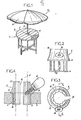
L'invention sera bien comprise d'ailleurs à l'aide de la description qui suit, en référence au dessin schématique annexé représentant, à titre d'exemple non limitatif, une forme d'exécution de cette bague de serrage pour parasol, dans le cas où ce parasol est adapté sur une table :
- Figure 1 est une vue en perspective du parasol et de la table;
- Figures 2 et 3 sont, à plus grande échelle, des vues respectivement en élévation et en plan par dessus de la bague de serrage, et
- Figure 4 est une vue en coupe verticale de la bague en position dans la table.
- Figure 1 is a perspective view of the parasol and the table;
- FIGS. 2 and 3 are, on a larger scale, views respectively in elevation and in plan from above the clamping ring, and
- Figure 4 is a vertical sectional view of the ring in position in the table.
A la figure 1, 1 désigne de façon générale une table et 2 désigne le parasol, constitué d'un mât :3 et d'une tête 4 jouant à proprement parler le rôle de parasol.In FIG. 1, 1 generally designates a table and 2 designates the parasol, consisting of a mast: 3 and a head 4 strictly speaking playing the role of parasol.
Comme cela est connu en soi, le plateau 5 de la table 1 présente un trou 6 destiné au passage du mât 3 du parasol; mais conformément à l'invention, le trou 6 sert de logement à une bague 7 dont le rôle est de servir au passage et au blocage du mât 3 du parasol.As is known per se, the
Cette bague 7, qui est représentée en détail aux figures 2 à 4, se termine à sa partie supérieure et à sa partie inférieure par des épaulements qui, désignés respectivement par 8 et par 9, ont un écartement légèrement supérieur à l'épaisseur du plateau 5, ou du moins à l'épaisseur du plateau dans sa zone située à la périphérie du trou 6; et sur sa face extérieure, la bague 7 présente des fines nervures longitudinales 10 qui s'étendent entre les épaulements 8 et 9 et sont destinées, comme cela sera décrit ci-après, à permettre un bon accrochage de la bague à l'intérieur du trou 6 du plateau de la table.This ring 7, which is shown in detail in FIGS. 2 to 4, ends at its upper part and at its lower part by shoulders which, designated respectively by 8 and by 9, have a spacing slightly greater than the thickness of the plate. 5, or at least the thickness of the plate in its zone situated on the periphery of the
La bague 7 présente deux autres particularités essentielles, à savoir :
- - elle comporte une fente radiale 12 s'étendant sur toute son épaisseur et sur toute sa hauteur,
- - et elle comporte, dans une zone de sa partie supérieure, une
ceinture 13 dans laquelle est aménagé un trou taraudé 14 dont la direction est à la fois radiale et oblique par rapport à l'axe longitudinal de la bague. Ce trou taraudé est destiné au vissage de la tige filetée 15 d'une vis dont latête 16 se trouve située au-dessus duplateau 5 de la table, lorsque la bague 7 a été introduite dans letrou 6 de ce plateau.
- it has a
radial slot 12 extending over its entire thickness and over its entire height, - - And it comprises, in a region of its upper part, a
belt 13 in which is arranged a tappedhole 14 whose direction is both radial and oblique with respect to the longitudinal axis of the ring. This tapped hole is intended for screwing the threadedrod 15 with a screw whosehead 16 is located above thetray 5 of the table, when the ring 7 has been introduced into thehole 6 of this tray.
Les modes d'utilisation et de fonctionnement de cette bague de serrage se conçoivent aisément : grâce à son élasticité transversale résultant de la présence de sa fente 12, la bague 7 est facilement introduite à l'intérieur du trou 6 aménagé dans le plateau 5 de la table; et elle s'y maintient d'elle-même, en raison de la présence de ses deux épaulements respectivement supérieur 8 et inférieur 9. La bague ayant ainsi été mise en place dans le plateau de la table, le mât 3 du parasol est lui-même introduit dans la bague et y coulisse librement en translation et en rotation, car son diamètre extérieur est inférieur au diamètre intérieur de la bague 7.The modes of use and operation of this clamping ring are easily conceivable: thanks to its transverse elasticity resulting from the presence of its
Lorsque la position la plus favorable a été donnée au parasol par rapport à la table, l'immobilisation de l'ensemble est obtenue par simple vissage de la vis 16. Ce vissage amène en effet la pointe de la vis à prendre appui contre le mât 3 du parasol, ce qui amène la bague 7 à s'expandre radialement grâce à sa fente 12, et à s'immobiliser ainsi à l'intérieur du trou 6 que comporte le plateau 5 de la table; au cours de cette expansion de la bague, les nervures 10 de la bague s'ancrent en effet à l'intérieur du trou 6 du plateau, de telle sorte que la bague ne peut pas tourner par rapport à la table. Le mât 3 du parasol peut lui-même présenter un relief extérieur tel que, grâce au serrage de la vis 16, il ne puisse pas tourner par rapport à la vis. Des nervures intérieures peuvent d'ailleurs aussi être prévues dans la bague 7 pour éviter toute possibilité de rotation du mât lorsqu'il est maintenu en appui contre la bague par serrage de la vis.When the most favorable position has been given to the parasol with respect to the table, the immobilization of the assembly is obtained by simple screwing of the
Il est à remarquer que la fente 12 de la bague 7 est relativement large, comme le montre bien la figure 3. Cette largeur permet de diminuer élastiquement et suffisamment le diamètre de la bague pour faciliter son introdu ction dans le trou 6 du plateau 5 de la table; mais cette largeur est aussi prévue pour permettre le libre passage d'au moins un conducteur électrique. Il est ainsi possible de faire passer et arriver par dessous la table le ou les conducteurs électriques servant à l'alimentation d'un éclairage ou de tout autre appareil placé au-dessus ou sur la table.It should be noted that the
Comme il va de soi, l'invention ne se limite pas à la seule forme d'exécution de cette bague de serrage qui a été ci-dessus indiquée à titre d'exemple; elle en embrasse, au contraire, toutes les variantes de réalisation, quel que soit bien entendu le matériau de la bague; et c'est ainsi que dans le cas d'une bague constituée en résine synthétique moulée, tel qu'en polyamide, il est avantageux de prévoir dans sa paroi interne de larges nervures longitudinales dont le but essentiel est de diminuer le poids et donc le prix de la bague. Il est en outre évident qu'une bague de serrage conforme à l'invention peut être utilisée pour l'immobilisation d'un parasol, non pas seulement par rapport à une table mais aussi par rapport à tout autre meuble, par exemple une chaise longue, l'essentiel étant qu'un trou soit percé dans le meuble pour servir de logement à la bague de serrage du mât du parasol.It goes without saying that the invention is not limited to the sole embodiment of this clamping ring which has been indicated above by way of example; on the contrary, it embraces all the variant embodiments thereof, whatever the material of the ring is of course; and it is thus that in the case of a ring made of molded synthetic resin, such as polyamide, it is advantageous to provide in its internal wall of large longitudinal ribs whose essential purpose is to reduce the weight and therefore the price of the ring. It is also obvious that a clamping ring according to the invention can be used for immobilizing a parasol, not only in relation to a table but also in relation to any other piece of furniture, for example a lounge chair , the main thing is that a hole is drilled in the furniture to serve as a housing for the parasol pole clamping ring.
Claims (3)
Priority Applications (1)
| Application Number | Priority Date | Filing Date | Title |
|---|---|---|---|
| AT81420107T ATE5989T1 (en) | 1980-07-22 | 1981-07-16 | CLAMPING RING FOR A PARASOL. |
Applications Claiming Priority (2)
| Application Number | Priority Date | Filing Date | Title |
|---|---|---|---|
| FR8016395 | 1980-07-22 | ||
| FR8016395A FR2487182A1 (en) | 1980-07-22 | 1980-07-22 | CLAMP RING FOR PARASOL |
Publications (3)
| Publication Number | Publication Date |
|---|---|
| EP0044796A2 true EP0044796A2 (en) | 1982-01-27 |
| EP0044796A3 EP0044796A3 (en) | 1982-02-03 |
| EP0044796B1 EP0044796B1 (en) | 1984-01-25 |
Family
ID=9244511
Family Applications (1)
| Application Number | Title | Priority Date | Filing Date |
|---|---|---|---|
| EP81420107A Expired EP0044796B1 (en) | 1980-07-22 | 1981-07-16 | Clamping-sleeve for a parasol |
Country Status (6)
| Country | Link |
|---|---|
| US (1) | US4353659A (en) |
| EP (1) | EP0044796B1 (en) |
| AT (1) | ATE5989T1 (en) |
| CA (1) | CA1158953A (en) |
| DE (1) | DE3162032D1 (en) |
| FR (1) | FR2487182A1 (en) |
Cited By (5)
| Publication number | Priority date | Publication date | Assignee | Title |
|---|---|---|---|---|
| FR2653644A1 (en) * | 1989-10-31 | 1991-05-03 | Jose Corominas Francisco | Parasol support system combined with table |
| DE9209715U1 (en) * | 1992-07-20 | 1992-11-26 | Langer, Georg, 5828 Ennepetal | Clamping screw |
| WO1999051122A1 (en) * | 1998-04-01 | 1999-10-14 | Gian Paolo Zandonella | Device for maintaining a parasol or the like in a piece of furniture |
| FR2907521A1 (en) * | 2006-10-19 | 2008-04-25 | Maurice Aiach | Support maintaining and locking device for umbrella mast, has fixation kit separated into upper and lower parts respectively comprising two central orifices, where upper part has roller introduced in threaded hole to lock/unlock kit on mast |
| EP1935285A1 (en) * | 2006-12-23 | 2008-06-25 | Wolfgang Männer | Device for the placement, storage and/or hanging of objects to a mast, a pole, a support, a railing or the like |
Families Citing this family (32)
| Publication number | Priority date | Publication date | Assignee | Title |
|---|---|---|---|---|
| US4724773A (en) * | 1986-02-03 | 1988-02-16 | Newberry Tim R | Portable, pedestal table for hot tubs, spas and whirlpools |
| DE3605747A1 (en) * | 1986-02-22 | 1987-08-27 | Bilgery Karl Dipl Rer Pol Tech | Threaded cone clamping bush |
| US4734301A (en) * | 1986-03-24 | 1988-03-29 | Mckinney Nancy E | Artificial tree |
| DE3635097A1 (en) * | 1986-10-15 | 1988-04-21 | Kortenbach Verwaltung | STAND UMBRELLA WITH A DEVICE FOR CLAMPING THE UMBRELLA IN A FOOT TUBE |
| US5318260A (en) * | 1992-10-19 | 1994-06-07 | Sunbeam Corporation | Table leg brace assembly |
| GB2331452B (en) * | 1997-11-18 | 2001-05-09 | George William Tomkinson | Parasol mounting arrangement |
| FR2780431B1 (en) * | 1998-06-29 | 2000-08-25 | Creaplus Sarl | DEVICE FOR LOCKING AND HOLDING AN umbrella mast |
| USD412254S (en) * | 1998-11-11 | 1999-07-27 | Kingsley-Bate Co. Ltd. | Dining table |
| NL1010633C2 (en) | 1998-11-23 | 2000-05-24 | Franciscus Antonius Johannes A | Combined plant container and support for garden parasol has concentric pot with central collar which fits over shaft of parasol support |
| US6109279A (en) * | 1998-12-31 | 2000-08-29 | Kloss; Robert P. | Locking device for an umbrella and method of use |
| US6209147B1 (en) * | 1998-12-31 | 2001-04-03 | Michael David Wheaton | Underwater attachment system |
| DE19920417C2 (en) * | 1999-05-04 | 2002-08-14 | Simon Paul | Height-adjustable one-leg table with clamp fastening system for connecting the table top to the table leg |
| WO2004101915A1 (en) * | 2003-05-15 | 2004-11-25 | Wayne Peter Killip | Shaft clamp assembly |
| US6957876B1 (en) * | 2003-08-13 | 2005-10-25 | Original Idea, Inc. | Portable bar |
| US20060272555A1 (en) * | 2005-06-06 | 2006-12-07 | Brown Jordan International, Inc. | Umbrella table with oversized opening for umbrella pole |
| GB2430355A (en) * | 2005-09-21 | 2007-03-28 | Emma Langlois | Double sun lounger |
| US7585552B2 (en) * | 2006-03-17 | 2009-09-08 | Melinda Joanne Meseke | Apparatus and method of assembling an artificial tree and table surface decoration assembly |
| US20080070753A1 (en) * | 2006-09-13 | 2008-03-20 | Suida Jeffrey R | Portable pole-dancing assembly |
| US8316602B2 (en) * | 2006-11-28 | 2012-11-27 | Ps Furniture, Inc. | Portable table construction and method for making the same |
| US7549430B1 (en) * | 2007-02-15 | 2009-06-23 | Furniture Leisure, Inc. | Secured umbrella and table assembly |
| US8607714B2 (en) * | 2010-10-15 | 2013-12-17 | Charles E. Ramberg | Shade structure |
| US9243747B2 (en) * | 2010-10-15 | 2016-01-26 | Charles E. Ramberg | Shade structure |
| US8875723B2 (en) * | 2011-12-28 | 2014-11-04 | Kent L. Brown | Counter balanced cover for table top |
| US9717350B2 (en) * | 2012-08-10 | 2017-08-01 | Robert DeMars | Portable bar and accessories kit |
| US9713367B2 (en) * | 2014-09-02 | 2017-07-25 | Ronald Duhon | Umbrella shaft assembly |
| US11910891B2 (en) | 2015-10-09 | 2024-02-27 | Current Products Corp. | Umbrella system |
| US11076663B2 (en) | 2015-10-09 | 2021-08-03 | Current Products Corp. | Umbrella system |
| US10039353B2 (en) * | 2015-10-09 | 2018-08-07 | Current Products Corp. | Umbrella system |
| US10533591B2 (en) * | 2015-10-28 | 2020-01-14 | Rene Machado Guerra | Securing device for table or other surface |
| US10687616B2 (en) * | 2018-09-03 | 2020-06-23 | Darren T. Brennan | Table top fence rail system |
| US11910890B2 (en) | 2020-07-16 | 2024-02-27 | Current Products Corp. | Umbrella system |
| WO2022212826A1 (en) * | 2021-04-01 | 2022-10-06 | Laporte Darren | Modular umbrella |
Citations (12)
| Publication number | Priority date | Publication date | Assignee | Title |
|---|---|---|---|---|
| US2190222A (en) * | 1937-10-27 | 1940-02-13 | Bernard J Strasser | Portable table structure |
| US2603543A (en) * | 1949-05-28 | 1952-07-15 | Rene E Barbin | Picnic table with adjustable top |
| US2621007A (en) * | 1948-08-21 | 1952-12-09 | Rene E Barbin | Knockdown stand for camping and picnics |
| GB836167A (en) * | 1957-10-03 | 1960-06-01 | British Thomson Houston Co Ltd | Improvements in driving keys for machine parts |
| FR1295885A (en) * | 1960-07-25 | 1962-06-08 | Dodge Mfg Corp | Shaft mounting sleeve |
| FR1403403A (en) * | 1964-07-29 | 1965-06-18 | System for quick anchoring and fixing to the ground of masts, poles, tubes and similar objects | |
| US3434484A (en) * | 1967-06-19 | 1969-03-25 | Luciano L Dilullo | Tiltable table for an umbrella |
| GB1273776A (en) * | 1969-05-09 | 1972-05-10 | Corfield Ducor Ltd | Support |
| FR2259563A1 (en) * | 1974-02-05 | 1975-08-29 | Lallemand Ets | Circular tubular frame garden table - has removable top sections clipping onto two concentric frame rings |
| FR2298682A1 (en) * | 1975-01-23 | 1976-08-20 | Voest Ag | PO DEVICE |
| US3990671A (en) * | 1974-10-15 | 1976-11-09 | Seyler Robert J | Non-stripping holder with set screw |
| CA1028475A (en) * | 1976-02-25 | 1978-03-28 | Donald Curtis | Fitting for playground structure |
Family Cites Families (8)
| Publication number | Priority date | Publication date | Assignee | Title |
|---|---|---|---|---|
| US1191078A (en) * | 1915-04-22 | 1916-07-11 | Raymond M Hutton | Armored-cable coupling. |
| US1696288A (en) * | 1926-05-17 | 1928-12-25 | Underwood Frank Karl | Tree holder |
| US1787669A (en) * | 1928-06-02 | 1931-01-06 | Thomas & Betts Corp | Cable connecter |
| GB324057A (en) * | 1928-10-16 | 1930-01-16 | Douglas David Erskine Little | Improvements in or relating to garden or like umbrellas |
| US2522172A (en) * | 1945-07-16 | 1950-09-12 | Arrow Hart & Hegeman Electric | Electric switch mounting means |
| US2465844A (en) * | 1947-11-05 | 1949-03-29 | Ralph E Brushaber | Fitting of connecting bx cables to outlet boxes |
| US2743146A (en) * | 1952-10-09 | 1956-04-24 | William H Wheeler | Umbrella tables and umbrella engaging means therefor |
| GB946629A (en) * | 1961-12-11 | 1964-01-15 | Ass Elect Ind | Improvements relating to clamping glands |
-
1980
- 1980-07-22 FR FR8016395A patent/FR2487182A1/en active Granted
-
1981
- 1981-07-16 EP EP81420107A patent/EP0044796B1/en not_active Expired
- 1981-07-16 DE DE8181420107T patent/DE3162032D1/en not_active Expired
- 1981-07-16 AT AT81420107T patent/ATE5989T1/en active
- 1981-07-20 US US06/284,992 patent/US4353659A/en not_active Expired - Fee Related
- 1981-07-21 CA CA000382138A patent/CA1158953A/en not_active Expired
Patent Citations (12)
| Publication number | Priority date | Publication date | Assignee | Title |
|---|---|---|---|---|
| US2190222A (en) * | 1937-10-27 | 1940-02-13 | Bernard J Strasser | Portable table structure |
| US2621007A (en) * | 1948-08-21 | 1952-12-09 | Rene E Barbin | Knockdown stand for camping and picnics |
| US2603543A (en) * | 1949-05-28 | 1952-07-15 | Rene E Barbin | Picnic table with adjustable top |
| GB836167A (en) * | 1957-10-03 | 1960-06-01 | British Thomson Houston Co Ltd | Improvements in driving keys for machine parts |
| FR1295885A (en) * | 1960-07-25 | 1962-06-08 | Dodge Mfg Corp | Shaft mounting sleeve |
| FR1403403A (en) * | 1964-07-29 | 1965-06-18 | System for quick anchoring and fixing to the ground of masts, poles, tubes and similar objects | |
| US3434484A (en) * | 1967-06-19 | 1969-03-25 | Luciano L Dilullo | Tiltable table for an umbrella |
| GB1273776A (en) * | 1969-05-09 | 1972-05-10 | Corfield Ducor Ltd | Support |
| FR2259563A1 (en) * | 1974-02-05 | 1975-08-29 | Lallemand Ets | Circular tubular frame garden table - has removable top sections clipping onto two concentric frame rings |
| US3990671A (en) * | 1974-10-15 | 1976-11-09 | Seyler Robert J | Non-stripping holder with set screw |
| FR2298682A1 (en) * | 1975-01-23 | 1976-08-20 | Voest Ag | PO DEVICE |
| CA1028475A (en) * | 1976-02-25 | 1978-03-28 | Donald Curtis | Fitting for playground structure |
Cited By (5)
| Publication number | Priority date | Publication date | Assignee | Title |
|---|---|---|---|---|
| FR2653644A1 (en) * | 1989-10-31 | 1991-05-03 | Jose Corominas Francisco | Parasol support system combined with table |
| DE9209715U1 (en) * | 1992-07-20 | 1992-11-26 | Langer, Georg, 5828 Ennepetal | Clamping screw |
| WO1999051122A1 (en) * | 1998-04-01 | 1999-10-14 | Gian Paolo Zandonella | Device for maintaining a parasol or the like in a piece of furniture |
| FR2907521A1 (en) * | 2006-10-19 | 2008-04-25 | Maurice Aiach | Support maintaining and locking device for umbrella mast, has fixation kit separated into upper and lower parts respectively comprising two central orifices, where upper part has roller introduced in threaded hole to lock/unlock kit on mast |
| EP1935285A1 (en) * | 2006-12-23 | 2008-06-25 | Wolfgang Männer | Device for the placement, storage and/or hanging of objects to a mast, a pole, a support, a railing or the like |
Also Published As
| Publication number | Publication date |
|---|---|
| CA1158953A (en) | 1983-12-20 |
| US4353659A (en) | 1982-10-12 |
| EP0044796A3 (en) | 1982-02-03 |
| FR2487182A1 (en) | 1982-01-29 |
| FR2487182B1 (en) | 1983-07-22 |
| DE3162032D1 (en) | 1984-03-01 |
| ATE5989T1 (en) | 1984-02-15 |
| EP0044796B1 (en) | 1984-01-25 |
Similar Documents
| Publication | Publication Date | Title |
|---|---|---|
| EP0044796B1 (en) | Clamping-sleeve for a parasol | |
| FR2709405A1 (en) | Sliding stud for moving loads, especially furniture | |
| FR2561482A1 (en) | ELECTROLUMINESCENT DIODE MOUNT | |
| FR2817164A1 (en) | SUPPORT BASE FOR A SHOE ON A BOARD, THE BASE INCLUDING AN ANGULAR ORIENTATION DEVICE RELATIVE TO THE BOARD | |
| FR2767027A1 (en) | VOLATILE PREVENTION DEVICE | |
| EP3336277B1 (en) | Element supporting spacing parts | |
| EP0077695B1 (en) | Fixation element with a captive nut | |
| BE525983A (en) | ||
| FR2528482A1 (en) | Moulded feet of adjustable height for supporting paving slabs etc. - assembled from polypropylene mouldings with stepped rib faces enclosed beneath an expanded rubber cover | |
| EP1114656B1 (en) | Device for supporting the front boot portion on a ski | |
| FR2558682A1 (en) | Tubular stay/stake | |
| EP1559842B1 (en) | Deck, in particular for recreation purpose | |
| FR2514543A1 (en) | Turntable with integral record clamp removing warps - uses ring mounted on threaded posts, raised and lowered by captive pinion meshing with fixed gear | |
| FR2620872A1 (en) | Electrical lamp-holder for lamps with a screw-type or bayonet-type cap | |
| FR2589708A1 (en) | Device for stabilising containers, in particular on cooking surfaces | |
| FR3088171A1 (en) | RAMPING ANTI-INSECT DEVICE, ESPECIALLY ANTI-PUNISHED, SUITABLE FOR PREVENTING INSECTS FROM HAVING A PREDETERMINED OBJECT | |
| FR2591450A3 (en) | Device for holding the pole of a parasol in the opening of a table top | |
| EP0572310A1 (en) | Anti-static glider for foot of furniture or similar | |
| FR2776809A1 (en) | Support for holding documents or notices | |
| FR2857834A1 (en) | Universal clamp for fixing object e.g. bottle, to dress or wall, has clamping part with branches and curved part forming clamping hook to engage in dress, and elastic band to maintain object between itself and clamping part | |
| FR2481196A1 (en) | Sectional sporting trophy cup - has handles projecting from collar locked between cup and base by stud with lock-nuts | |
| FR2547089A2 (en) | Slim, internally-lit display panel | |
| BE512780A (en) | ||
| CH685087B5 (en) | watchcase with rotating bezel. | |
| FR2615075A1 (en) | Spike support bar-insert for a shoe sole, method of manufacture and shoe thus obtained |
Legal Events
| Date | Code | Title | Description |
|---|---|---|---|
| PUAI | Public reference made under article 153(3) epc to a published international application that has entered the european phase |
Free format text: ORIGINAL CODE: 0009012 |
|
| PUAL | Search report despatched |
Free format text: ORIGINAL CODE: 0009013 |
|
| AK | Designated contracting states |
Designated state(s): AT BE CH DE GB IT LU NL SE |
|
| AK | Designated contracting states |
Designated state(s): AT BE CH DE GB IT LU NL SE |
|
| 17P | Request for examination filed |
Effective date: 19820316 |
|
| ITF | It: translation for a ep patent filed | ||
| GRAA | (expected) grant |
Free format text: ORIGINAL CODE: 0009210 |
|
| AK | Designated contracting states |
Designated state(s): AT BE CH DE GB IT LI LU NL SE |
|
| REF | Corresponds to: |
Ref document number: 5989 Country of ref document: AT Date of ref document: 19840215 Kind code of ref document: T |
|
| REF | Corresponds to: |
Ref document number: 3162032 Country of ref document: DE Date of ref document: 19840301 |
|
| PGFP | Annual fee paid to national office [announced via postgrant information from national office to epo] |
Ref country code: AT Payment date: 19840628 Year of fee payment: 4 |
|
| PGFP | Annual fee paid to national office [announced via postgrant information from national office to epo] |
Ref country code: SE Payment date: 19840630 Year of fee payment: 4 Ref country code: BE Payment date: 19840630 Year of fee payment: 4 |
|
| PGFP | Annual fee paid to national office [announced via postgrant information from national office to epo] |
Ref country code: CH Payment date: 19840702 Year of fee payment: 4 |
|
| PG25 | Lapsed in a contracting state [announced via postgrant information from national office to epo] |
Ref country code: LU Free format text: LAPSE BECAUSE OF NON-PAYMENT OF DUE FEES Effective date: 19840731 |
|
| PGFP | Annual fee paid to national office [announced via postgrant information from national office to epo] |
Ref country code: NL Payment date: 19840731 Year of fee payment: 4 |
|
| PGFP | Annual fee paid to national office [announced via postgrant information from national office to epo] |
Ref country code: DE Payment date: 19840803 Year of fee payment: 4 |
|
| PLBE | No opposition filed within time limit |
Free format text: ORIGINAL CODE: 0009261 |
|
| STAA | Information on the status of an ep patent application or granted ep patent |
Free format text: STATUS: NO OPPOSITION FILED WITHIN TIME LIMIT |
|
| 26N | No opposition filed | ||
| PG25 | Lapsed in a contracting state [announced via postgrant information from national office to epo] |
Ref country code: AT Effective date: 19850716 |
|
| PG25 | Lapsed in a contracting state [announced via postgrant information from national office to epo] |
Ref country code: SE Effective date: 19850717 |
|
| PG25 | Lapsed in a contracting state [announced via postgrant information from national office to epo] |
Ref country code: LI Effective date: 19850731 Ref country code: CH Effective date: 19850731 Ref country code: BE Effective date: 19850731 |
|
| BERE | Be: lapsed |
Owner name: SOC. D'EXPLOITATION CLAIRITEX Effective date: 19850731 |
|
| PG25 | Lapsed in a contracting state [announced via postgrant information from national office to epo] |
Ref country code: NL Effective date: 19860201 |
|
| GBPC | Gb: european patent ceased through non-payment of renewal fee | ||
| NLV4 | Nl: lapsed or anulled due to non-payment of the annual fee | ||
| REG | Reference to a national code |
Ref country code: CH Ref legal event code: PL |
|
| PG25 | Lapsed in a contracting state [announced via postgrant information from national office to epo] |
Ref country code: DE Effective date: 19860402 |
|
| PG25 | Lapsed in a contracting state [announced via postgrant information from national office to epo] |
Ref country code: GB Effective date: 19881118 |
|
| EUG | Se: european patent has lapsed |
Ref document number: 81420107.5 Effective date: 19860730 |