EP0572310A1 - Anti-static glider for foot of furniture or similar - Google Patents
Anti-static glider for foot of furniture or similar Download PDFInfo
- Publication number
- EP0572310A1 EP0572310A1 EP93401332A EP93401332A EP0572310A1 EP 0572310 A1 EP0572310 A1 EP 0572310A1 EP 93401332 A EP93401332 A EP 93401332A EP 93401332 A EP93401332 A EP 93401332A EP 0572310 A1 EP0572310 A1 EP 0572310A1
- Authority
- EP
- European Patent Office
- Prior art keywords
- orifice
- pivot
- shoulder
- spring
- skate according
- Prior art date
- Legal status (The legal status is an assumption and is not a legal conclusion. Google has not performed a legal analysis and makes no representation as to the accuracy of the status listed.)
- Granted
Links
- 239000004020 conductor Substances 0.000 claims abstract description 11
- 230000006835 compression Effects 0.000 claims abstract description 5
- 238000007906 compression Methods 0.000 claims abstract description 5
- 239000000463 material Substances 0.000 claims description 18
- 229910000831 Steel Inorganic materials 0.000 claims description 4
- 239000010959 steel Substances 0.000 claims description 4
- -1 P.V.C. Polymers 0.000 claims description 3
- 239000002216 antistatic agent Substances 0.000 claims description 3
- 229910001220 stainless steel Inorganic materials 0.000 claims description 3
- 239000010935 stainless steel Substances 0.000 claims description 3
- 239000004743 Polypropylene Substances 0.000 claims description 2
- 239000012777 electrically insulating material Substances 0.000 claims description 2
- 238000003780 insertion Methods 0.000 claims description 2
- 230000037431 insertion Effects 0.000 claims description 2
- 239000004033 plastic Substances 0.000 claims description 2
- 229920001155 polypropylene Polymers 0.000 claims description 2
- 230000005611 electricity Effects 0.000 description 7
- 230000003068 static effect Effects 0.000 description 6
- 208000031968 Cadaver Diseases 0.000 description 5
- OKTJSMMVPCPJKN-UHFFFAOYSA-N Carbon Chemical compound [C] OKTJSMMVPCPJKN-UHFFFAOYSA-N 0.000 description 3
- 229910052799 carbon Inorganic materials 0.000 description 3
- 239000012535 impurity Substances 0.000 description 2
- 238000009825 accumulation Methods 0.000 description 1
- 238000004140 cleaning Methods 0.000 description 1
- 230000000295 complement effect Effects 0.000 description 1
- 238000010276 construction Methods 0.000 description 1
- 230000006378 damage Effects 0.000 description 1
- 239000007788 liquid Substances 0.000 description 1
- 210000000056 organ Anatomy 0.000 description 1
- 230000001590 oxidative effect Effects 0.000 description 1
- 230000035515 penetration Effects 0.000 description 1
- 238000006748 scratching Methods 0.000 description 1
- 230000002393 scratching effect Effects 0.000 description 1
- XLYOFNOQVPJJNP-UHFFFAOYSA-N water Substances O XLYOFNOQVPJJNP-UHFFFAOYSA-N 0.000 description 1
Images
Classifications
-
- A—HUMAN NECESSITIES
- A47—FURNITURE; DOMESTIC ARTICLES OR APPLIANCES; COFFEE MILLS; SPICE MILLS; SUCTION CLEANERS IN GENERAL
- A47B—TABLES; DESKS; OFFICE FURNITURE; CABINETS; DRAWERS; GENERAL DETAILS OF FURNITURE
- A47B91/00—Feet for furniture in general
- A47B91/06—Gliders or the like
Definitions
- the present invention relates to the pads for the feet of furniture, seats or the like making it possible to move this furniture on the ground and also to discharge static electricity, very troublesome for the users of this furniture, capable of being stored by this furniture when, by their feet, they rub on the ground, for example on carpet made of synthetic or similar material.
- Patches for furniture feet are already known which allow the static electricity stored during their movement on the ground to be discharged.
- These so-called “antistatic” pads are, for example, those made of a material loaded with carbon.
- Such a skid is thus a good enough conductor of electricity to allow that stored by the piece of furniture to flow towards the ground, but has the drawback of scratching the ground when moving the piece of furniture and leaving black marks there. which are carbon deposits. It cannot therefore, in particular, be used in places such as clean rooms, for example in the electronics, aeronautical or aerospace industries.
- the object of the present invention is therefore to produce a shoe foot pad, which overcomes the drawbacks of the shoe pads of the prior art mentioned above.
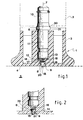
- the single figure represents a preferred embodiment of a shoe 1 for a furniture leg, the latter being very schematically represented in 2.
- This shoe 1 comprises a base 3 comprising a surface 4 capable of making contact with a ground 5, this surface being for example flat, as illustrated in the figure.
- This base is made of a first material which can be an electrically insulating material chosen, for example, from the following materials: plastic, P.V.C., advantageously polypropylene.
- An orifice 6 is produced by crossing right through the base 3 along an axis 7 substantially perpendicular to the contact surface 4.
- the section of the end 8 of this orifice 6 opening onto the contact surface 4 comprises a first re-entering shoulder 9.
- the shoe also includes a pivot 10 disposed in the orifice 6, the length of the part 11 of the pivot 10 plunging into the orifice being less than the length of the orifice, so as to leave a free space 12 between its end 13 and the shoulder 9.
- the pivot 10 is made of a second electrically conductive material, for example steel.
- this pivot 10 has a shoulder 30 which allows, for example, to limit its penetration into the orifice 6.
- This shoulder 30 is arranged to, preferably, cooperate with the edge 31 of the orifice 6 opposite the end 8 opening onto the contact surface 4, but may consist of a collar which has the advantage of defining two shoulders, the shoulder 30 defined above and another shoulder making it possible, in a manner known in itself, to limit the insertion of the pivot into the base of the cabinet 2.
- a body 14 is slidably mounted so that it is able to come into contact with the first shoulder 9 and that a first 15 of its ends protrudes relative to the contact surface. 4.
- the body 14 is made of a third material, also electrically conductive, such as steel and more advantageously stainless steel.
- a spring 16 mounted in compression between the second end of the body 14 and the end 13 of the pivot 10 plunging into the orifice 6.
- the spring is made of a fourth electrically conductive material, for example steel. It is specified that by “spring” is meant any elastic means making it possible to exert a couple of opposite forces between two points while tending to move them away, the spring illustrated, of cylindrical type with distant turns, being only one possible embodiment.
- the two ends of the spring 16 can be directly in contact with the body 14 and the pivot 10, but the shoe can advantageously include means for electrically connecting the two ends of the spring 16 respectively with the pivot and the body.
- These means comprise at least one pad 17 interposed between one of the ends of the spring and the second end of the body 14. In the embodiment illustrated in the figure, they include another 18 between the other end of the spring and the end 13 of pivot 10.
- the tablet is made of a fifth material having a high calibrated electrical resistivity, for example a dissipative or antistatic material.
- a fifth material having a high calibrated electrical resistivity for example a dissipative or antistatic material.
- the body 14 can have different shapes. It will for example be constituted by a ball 20, as illustrated in FIG. 1.
- the shoulder 9 has the form of a concave surface in a spherical zone substantially complementary to the ball, the concave surface being turned towards the free space 12.
- the shape of a ball 20 given to the body 14 can, in certain cases in particular of the nature of the ground, present disadvantages. Indeed, by pivoting on itself, it facilitates the movement of the piece of furniture in all directions, but can also introduce impurities into the end 8 of the orifice 6. This accumulation of impurities can affect the pivoting of the ball and , above all, make a layer electrically insulating between it and, for example, the spring 16, at the risk of preventing the shoe from ensuring the discharge of static electricity as described below.
- the body 14 may it be advantageous to produce the body 14, as illustrated in FIG. 2, in the form of a stud 21 with an outgoing shoulder 22 on its end opposite its end 15 in contact with the ground, and being able to translate in the end 8 of the orifice 6 in the manner of a piston, in a translation limited by the cooperation of its outgoing shoulder 22 against the re-entering shoulder 9 of the end 8 of the orifice 6.
- the shoe 1 described above acts as follows, when it is mounted on a furniture leg 2:
- the piece of furniture When the piece of furniture has such a shoe, the latter bears on the ground 5 by its contact surface 4 and the end 15 of the body 14, ball 20 or the stud 21, held between the shoulder 9 and the spring 16, this spring ensuring constant contact of the body with the ground, even if the latter has slight differences in level, as well as electrical continuity between the body and the pivot. Therefore, all the static electricity which would have been stored by the piece of furniture, seat, etc., is led to the mass of the ground by way of the foot of the piece of furniture 2, the pivot 10, at least one patch 17, 18, the spring 16 and the body 14 which are all made of electrically conductive material.
- the pad 17 is advantageously made of a dissipative or antistatic material, with the aim of slowing the flow of static electricity towards the ground, so as not to create radio waves which can lead to the destruction of sensitive electronic organs.
- the ball shape 20 given to the body 14, as well as the semispherical shape given to the end 15 of the stud 21 in contact with the ground, has the advantage, compared to other shapes, of reducing the risks of scratches on this floor when moving the furniture, seat, etc., and this advantage is reinforced by the fact that the body 14 is made of stainless steel, which prevents it from oxidizing, in particular following its contact, for example during cleaning the floor with a liquid such as water or the like.
- the antistatic pad according to the invention has advantages compared to the pads described in the preamble. Its base can indeed be made of a material not loaded with carbon and will therefore not leave a trace or unsightly scratch on the ground. These pads can in particular equip the furniture and seats of so-called "white” rooms or the like. In addition, their structure allows them to compact shape which facilitates their construction and ensures them of good solidity, while allowing them to preserve aesthetic qualities.
Landscapes
- Footwear And Its Accessory, Manufacturing Method And Apparatuses (AREA)
- Elimination Of Static Electricity (AREA)
Abstract
Description
La présente invention concerne les patins pour pieds de meubles, sièges ou analogues permettant de déplacer ces meubles sur le sol et aussi de décharger l'électricité statique, très gênante pour les utilisateurs de ces meubles, susceptible d'être emmagasinée par ces meubles quand, par leurs pieds, ils frottent sur le sol, par exemple sur de la moquette en matériau synthétique ou analogue.The present invention relates to the pads for the feet of furniture, seats or the like making it possible to move this furniture on the ground and also to discharge static electricity, very troublesome for the users of this furniture, capable of being stored by this furniture when, by their feet, they rub on the ground, for example on carpet made of synthetic or similar material.
On connaît déjà des patins pour pieds de meubles qui permettent de décharger l'électricité statique emmagasinée lors de leur déplacement sur le sol. Ces patins dits "antistatiques" sont par exemple ceux qui sont réalisés en un matériau chargé en carbone. Un tel patin est ainsi assez bon conducteur de l'électricité pour permettre à celle emmagasinée par le meuble de s'écouler vers le sol, mais présente l'inconvénient de rayer le sol lors du déplacement du meuble et d'y laisser des traces noires qui sont des dépôts de carbone. ll ne peut donc pas, notamment, être utilisé dans des lieux comme des salles blanches, par exemple dans les industries électronique, aéronautique ou aérospatiale.Patches for furniture feet are already known which allow the static electricity stored during their movement on the ground to be discharged. These so-called "antistatic" pads are, for example, those made of a material loaded with carbon. Such a skid is thus a good enough conductor of electricity to allow that stored by the piece of furniture to flow towards the ground, but has the drawback of scratching the ground when moving the piece of furniture and leaving black marks there. which are carbon deposits. It cannot therefore, in particular, be used in places such as clean rooms, for example in the electronics, aeronautical or aerospace industries.
Il existe aussi des patins qui comportent une tige ou une patte conductrice frottant sur le sol. Mais cette patte se casse assez facilement ou s'use rapidement, ce qui ne lui permet pas d'assurer de façon fiable la décharge de l'électricité statique.There are also pads which have a rod or a conductive tab rubbing on the ground. But this tab breaks fairly easily or wears out quickly, which does not allow it to reliably ensure the discharge of static electricity.
La présente invention a ainsi pour but de réaliser un patin pour pied de meuble, qui pallie les inconvénients des patins de l'art antérieur rappelés ci-dessus.The object of the present invention is therefore to produce a shoe foot pad, which overcomes the drawbacks of the shoe pads of the prior art mentioned above.
Plus précisément, la présente invention a pour objet un patin pour pied de meuble ou analogue, caractérisé par le fait qu'il comporte:
- une embase en un premier matériau, ladite embase comportant une surface apte à prendre contact avec le sol,
- un orifice traversant ladite embase suivant un axe sensiblement perpendiculaire à la surface de contact, la section de l'extrémité dudit orifice débouchant sur ladite surface de contact comportant un premier épaulement rentrant,
- un pivot disposé dans ledit orifice, la longueur de la partie dudit pivot plongeant dans ledit orifice étant inférieure à la longueur dudit orifice, ledit pivot étant en un deuxième matériau électriquement conducteur,
- un corps monté coulissant dans ledit orifice du côté dudit premier épaulement, une première extrémité dudit corps faisant saillie par rapport à ladite surface de contact, ledit corps étant en un troisième matériau électriquement conducteur,
- un ressort monté en compression entre l'autre extrémité dudit corps et l'extrémité dudit pivot plongeant dans ledit orifice, ledit ressort étant en un quatrième matériau électriquement conducteur, et
- des moyens pour lier électriquement les deux extrémités dudit ressort, respectivement avec ledit pivot et ledit corps.
- a base made of a first material, said base comprising a surface capable of making contact with the ground,
- an orifice passing through said base along an axis substantially perpendicular to the contact surface, the section of the end of said orifice opening onto said contact surface comprising a first re-entrant shoulder,
- a pivot placed in said orifice, the length of the part of said pivot plunging into said orifice being less than the length of said orifice, said pivot being made of a second electrically conductive material,
- a body mounted to slide in said orifice on the side of said first shoulder, a first end of said body projecting from said contact surface, said body being made of a third electrically conductive material,
- a spring mounted in compression between the other end of said body and the end of said pivot plunging into said orifice, said spring being of a fourth electrically conductive material, and
- means for electrically connecting the two ends of said spring, respectively with said pivot and said body.
D'autres caractéristiques et avantages de la présente invention apparaîtront au cours de la description suivante donnée en regard du dessin annexé à titre illustratif mais nullement limitatif, dans lequel:
- La figure 1 représente, vu en coupe, un mode de réalisation d'un patin pour pied de meuble selon l'invention, et
- La figure 2 représente vue en coupe une partie d'un autre mode de réalisation d'un patin selon l'invention.
- FIG. 1 represents, seen in section, an embodiment of a shoe foot pad according to the invention, and
- 2 shows a sectional view of part of another embodiment of a skate according to the invention.
La figure unique représente un mode de réalisation préférentiel d'un patin 1 pour un pied de meuble, ce dernier étant très schématiquement représenté en 2.The single figure represents a preferred embodiment of a
Ce patin 1 comporte une embase 3 comprenant une surface 4 apte à prendre contact avec un sol 5, cette surface étant par exemple plane, comme illustré sur la figure. Cette embase est réalisée dans un premier matériau qui peut être un matériau électriquement isolant choisi, par exemple, parmi les matériaux suivants: plastique, P.V.C., avantageusement polypropylène.This
Un orifice 6 est réalisé en traversant de part en part l'embase 3 suivant un axe 7 sensiblement perpendiculaire à la surface de contact 4. En outre, la section de l'extrémité 8 de cet orifice 6 débouchant sur la surface de contact 4 comporte un premier épaulement rentrant 9.An
Le patin comporte aussi un pivot 10 disposé dans l'orifice 6, la longueur de la partie 11 du pivot 10 plongeant dans l'orifice étant inférieure à la longueur de l'orifice, de façon à laisser un espace libre 12 entre son extrémité 13 et l'épaulement 9. Le pivot 10 est réalisé en un deuxième matériau électriquement conducteur, par exemple de l'acier.The shoe also includes a
Avantageusement, ce pivot 10 comporte un épaulement 30 qui permet, par exemple, de limiter son enfoncement dans l'orifice 6. Cet épaulement 30 est agencé pour, préférentiellement, coopérer avec le bord 31 de l'orifice 6 opposé à l'extrémité 8 débouchant sur la surface de contact 4, mais peut être constitué par un collet qui présente l'avantage de définir deux épaulements, I'épaulement 30 défini ci-avant et un autre épaulement permettant, de façon connue en elle-même, de limiter l'enfoncement du pivot dans le pied du meuble 2.Advantageously, this
Dans l'espace libre 12 défini ci-avant, un corps 14 est monté coulissant de façon qu'il soit apte à venir au contact du premier épaulement 9 et qu'une première 15 de ses extrémités fasse saillie par rapport à la surface de contact 4. Le corps 14 est réalisé en un troisième matériau, lui aussi électriquement conducteur, comme de l'acier et plus avantageusement de l'acier inoxydable.In the
Dans cet espace libre 12 est en outre disposé un ressort 16, monté en compression entre la seconde extrémité du corps 14 et l'extrémité 13 du pivot 10 plongeant dans l'orifice 6. Le ressort est en un quatrième matériau électriquement conducteur, par exemple de l'acier. Il est précisé que par "ressort", on entend tout moyen élastique permettant d'exercer un couple de forces opposées entre deux points en tendant à les éloigner, le ressort illustré, de type cylindrique à spires éloignées, n'en étant qu'un mode de réalisation possible.In this
Les deux extrémités du ressort 16 peuvent être directement au contact du corps 14 et du pivot 10, mais le patin peut avantageusement comporter des moyens pour lier électriquement les deux extrémités du ressort 16 respectivement avec le pivot et le corps. Ces moyens comportent au moins une pastille 17 interposée entre l'une des extrémités du ressort et la seconde extrémité du corps 14. Dans le mode de réalisation illustré sur la figure, ils en comportent une autre 18 entre l'autre extrémité du ressort et l'extrémité 13 du pivot 10.The two ends of the
Avantageusement, la pastille est en un cinquième matériau présentant une résistivité électrique calibrée élevée, par exemple un matériau dissipatif ou antistatique. L'avantage conféré par cette caractéristique sera explicité ci-après.Advantageously, the tablet is made of a fifth material having a high calibrated electrical resistivity, for example a dissipative or antistatic material. The advantage conferred by this characteristic will be explained below.
Dans la présente description, le corps 14 peut présenter différentes formes. Il sera par exemple constitué par une bille 20, comme illustré sur la figure 1. Dans ce cas, l'épaulement 9 présente la forme d'une surface concave en zone sphérique sensiblement complémentaire de la bille, la surface concave étant tournée vers l'espace libre 12.In the present description, the
Cependant, si elle présente des avantages, la forme de bille 20 donnée au corps 14, peut, dans certains cas notamment de nature de sol, présenter des inconvénients. En effet en pivotant sur elle-même, elle facilite le déplacement du meuble dans tous les sens, mais peut également introduire des impuretés dans l'extrémité 8 de l'orifice 6. Cette accumulation d'impuretés peut nuire au pivotement de la bille et, surtout, réaliser une couche électriquement isolante entre elle et, par exemple, le ressort 16, au risque d'empêcher le patin d'assurer la décharge de l'électricité statique comme décrit ci-après.However, if it has advantages, the shape of a
Aussi, peut-il être avantageux de réaliser le corps 14, comme illustré sur la figure 2, sous la forme d'un téton 21 à épaulement sortant 22 sur son extrémité opposée à son extrémité 15 en contact avec le sol, et pouvant se translater dans l'extrémité 8 de l'orifice 6 à la manière d'un piston, dans une translation limitée par la coopération de son épaulement sortant 22 contre l'épaulement rentrant 9 de l'extrémité 8 de l'orifice 6.Also, may it be advantageous to produce the
Le patin 1 décrit ci-dessus agit de la façon suivante, quand il est monté sur un pied de meuble 2:The
Quand le meuble comporte un tel patin, ce dernier porte sur le sol 5 par sa surface de contact 4 et l'extrémité 15 du corps 14, bille 20 ou le téton 21, maintenu entre l'épaulement 9 et le ressort 16, ce ressort assurant un contact constant du corps avec le sol, même si ce dernier présente de légères dénivellations, ainsi qu'une continuité électrique entre le corps et le pivot. De ce fait, toute l'électricité statique qui aurait été emmagasinée par le meuble, siège, etc., est conduite à la masse du sol en cheminant par le pied du meuble 2, le pivot 10, au moins une pastille 17, 18, le ressort 16 et le corps 14 qui sont tous en matériau électriquement conducteur. Comme mentionné ci-avant, la pastille 17 est avantageusement en un matériau dissipatif ou antistatique, dans le but de ralentir l'écoulement de l'électricité statique vers le sol, afin de ne pas créer d'ondes radio pouvant entraîner la destruction d'organes électroniques sensibles.When the piece of furniture has such a shoe, the latter bears on the
La forme de bille 20 donnée au corps 14, ainsi que la forme semisphérique donnée à l'extrémité 15 du téton 21 en contact avec le sol, présente l'avantage, par rapport à d'autres formes, de diminuer les risques de rayures sur ce sol lors du déplacement du meuble, siège, etc., et cet avantage est renforcé par le fait que le corps 14 est en acier inoxydable, ce qui l'empêche de s'oxyder, notamment suite à son contact, par exemple lors du nettoyage du sol, avec un liquide comme de l'eau ou analogue.The
A la présente description, on constate que le patin antistatique selon l'invention présente des avantages par rapport aux patins décrits dans le préambule. Son embase peut en effet être réalisée en un matériau non chargé en carbone et ne laissera donc pas de trace ni de rayure disgracieuse sur le sol. Ces patins peuvent notamment équiper les meubles et sièges de salles dites "blanches" ou analogues. De plus, leur structure permet de leur donner une forme compacte qui facilite leur construction et les assurent d'une bonne solidité, tout en leur permettant de conserver des qualités esthétiques.In the present description, it can be seen that the antistatic pad according to the invention has advantages compared to the pads described in the preamble. Its base can indeed be made of a material not loaded with carbon and will therefore not leave a trace or unsightly scratch on the ground. These pads can in particular equip the furniture and seats of so-called "white" rooms or the like. In addition, their structure allows them to compact shape which facilitates their construction and ensures them of good solidity, while allowing them to preserve aesthetic qualities.
Claims (10)
Applications Claiming Priority (2)
| Application Number | Priority Date | Filing Date | Title |
|---|---|---|---|
| FR9206567A FR2691618B1 (en) | 1992-05-29 | 1992-05-29 | Antistatic pad for furniture leg. |
| FR9206567 | 1992-05-29 |
Publications (2)
| Publication Number | Publication Date |
|---|---|
| EP0572310A1 true EP0572310A1 (en) | 1993-12-01 |
| EP0572310B1 EP0572310B1 (en) | 1996-03-13 |
Family
ID=9430285
Family Applications (1)
| Application Number | Title | Priority Date | Filing Date |
|---|---|---|---|
| EP19930401332 Expired - Lifetime EP0572310B1 (en) | 1992-05-29 | 1993-05-25 | Anti-static glider for foot of furniture or similar |
Country Status (3)
| Country | Link |
|---|---|
| EP (1) | EP0572310B1 (en) |
| DE (1) | DE69301768D1 (en) |
| FR (1) | FR2691618B1 (en) |
Cited By (3)
| Publication number | Priority date | Publication date | Assignee | Title |
|---|---|---|---|---|
| US6111196A (en) * | 1996-02-28 | 2000-08-29 | Sony Corporation | Slide tray having a rolling conductive path |
| DE202005018857U1 (en) * | 2005-12-01 | 2007-04-12 | Sonnendorfer Horst | Transport role for a shopping cart |
| US20220225768A1 (en) * | 2021-01-18 | 2022-07-21 | Scott Randall Newman | Grounding Floor Glide for Shelving, Chairs, and Equipment to Reduce Risk from ESD (Electro-Static Discharge) and Protect Floors from Damage |
Citations (3)
| Publication number | Priority date | Publication date | Assignee | Title |
|---|---|---|---|---|
| US1839593A (en) * | 1929-06-12 | 1932-01-05 | Branche C Rice | Resilient glide for furniture |
| FR2642706A1 (en) * | 1989-02-09 | 1990-08-10 | Bruandet Sa | CASTER FOR A FURNITURE STAND OR THE LIKE ALLOWING THE DISCHARGE OF STATIC ELECTRICITY |
| DE3913720A1 (en) * | 1989-04-26 | 1990-10-31 | Stein & Co Paul Vom | Castor for furniture appts. etc. - provides castor wheel contact by contact element to allow discharge of static electricity |
-
1992
- 1992-05-29 FR FR9206567A patent/FR2691618B1/en not_active Expired - Fee Related
-
1993
- 1993-05-25 DE DE69301768T patent/DE69301768D1/en not_active Expired - Lifetime
- 1993-05-25 EP EP19930401332 patent/EP0572310B1/en not_active Expired - Lifetime
Patent Citations (3)
| Publication number | Priority date | Publication date | Assignee | Title |
|---|---|---|---|---|
| US1839593A (en) * | 1929-06-12 | 1932-01-05 | Branche C Rice | Resilient glide for furniture |
| FR2642706A1 (en) * | 1989-02-09 | 1990-08-10 | Bruandet Sa | CASTER FOR A FURNITURE STAND OR THE LIKE ALLOWING THE DISCHARGE OF STATIC ELECTRICITY |
| DE3913720A1 (en) * | 1989-04-26 | 1990-10-31 | Stein & Co Paul Vom | Castor for furniture appts. etc. - provides castor wheel contact by contact element to allow discharge of static electricity |
Cited By (3)
| Publication number | Priority date | Publication date | Assignee | Title |
|---|---|---|---|---|
| US6111196A (en) * | 1996-02-28 | 2000-08-29 | Sony Corporation | Slide tray having a rolling conductive path |
| DE202005018857U1 (en) * | 2005-12-01 | 2007-04-12 | Sonnendorfer Horst | Transport role for a shopping cart |
| US20220225768A1 (en) * | 2021-01-18 | 2022-07-21 | Scott Randall Newman | Grounding Floor Glide for Shelving, Chairs, and Equipment to Reduce Risk from ESD (Electro-Static Discharge) and Protect Floors from Damage |
Also Published As
| Publication number | Publication date |
|---|---|
| FR2691618B1 (en) | 1994-08-26 |
| EP0572310B1 (en) | 1996-03-13 |
| FR2691618A1 (en) | 1993-12-03 |
| DE69301768D1 (en) | 1996-04-18 |
Similar Documents
| Publication | Publication Date | Title |
|---|---|---|
| EP0044796B1 (en) | Clamping-sleeve for a parasol | |
| FR2611447A1 (en) | GLOVE IMPROVEMENT | |
| CH662473A5 (en) | DEVICE FOR PREVENTING PARKING OF VOLATILES ON BUILDING ELEMENTS. | |
| EP0572310B1 (en) | Anti-static glider for foot of furniture or similar | |
| FR2555418A1 (en) | Ski boot with leg part articulated on foot | |
| FR2512682A1 (en) | SKI BRAKE | |
| EP0382584B1 (en) | Static electricity discharging castor for furniture | |
| FR2630846A1 (en) | SUPPORT FOR TWO PLATES ASSEMBLED TO PRESENT INFORMATION AND / OR VARIOUS OBJECTS | |
| EP0099781A2 (en) | Sliding and elastically locking element for a floating caliper disc brake supported by a single column, and disc brake equipped with the same | |
| FR2598934A1 (en) | SECURITY FIXING OF A SHOE ON A SKI | |
| EP0536499B1 (en) | Interface plate for ski bindings | |
| FR2730383A1 (en) | Device to prevent birds, e.g. pigeons, from coming to rest on surfaces, e.g. window sills | |
| FR2707941A1 (en) | Protective device for wiper blade. | |
| FR2511197A1 (en) | Electrical contactor system for printed circuit boards - has upright single-point contact blades which maintain even contact by buckling flexing force | |
| FR2960823A1 (en) | ROULETTE FOR FOOT OF FURNITURE | |
| EP0865806B1 (en) | Safety heel hold-down for a ski | |
| FR2769239A1 (en) | DEVICE FOR RETAINING A SHOE ON A SNOWBOARD INTENDED FOR SNOW SURFING | |
| FR2940763A1 (en) | SNOW RACKET A CALE DE MONTEE | |
| FR2613947A1 (en) | Design of a judo mat | |
| CA1168273A (en) | Ski binding | |
| FR2683997A1 (en) | ANTI-SLIP DEVICE FOR AN UNSTABLE TUBULAR ELEMENT. | |
| FR2596257A1 (en) | Article of footwear for eliminating static electricity | |
| WO1995012342A1 (en) | Device for securing an elongated element such as a cane or the like when not in use | |
| FR2521844A1 (en) | Movable shock absorbent furniture castor - incorporates adaptor for tilt, with flexible bar and cavities | |
| FR2615747A1 (en) | Bearing piece for a ski binding including a low-friction coating |
Legal Events
| Date | Code | Title | Description |
|---|---|---|---|
| PUAI | Public reference made under article 153(3) epc to a published international application that has entered the european phase |
Free format text: ORIGINAL CODE: 0009012 |
|
| AK | Designated contracting states |
Kind code of ref document: A1 Designated state(s): DE ES GB IT |
|
| 17P | Request for examination filed |
Effective date: 19940530 |
|
| 17Q | First examination report despatched |
Effective date: 19950510 |
|
| GRAH | Despatch of communication of intention to grant a patent |
Free format text: ORIGINAL CODE: EPIDOS IGRA |
|
| GRAA | (expected) grant |
Free format text: ORIGINAL CODE: 0009210 |
|
| AK | Designated contracting states |
Kind code of ref document: B1 Designated state(s): DE ES GB IT |
|
| PG25 | Lapsed in a contracting state [announced via postgrant information from national office to epo] |
Ref country code: IT Free format text: LAPSE BECAUSE OF FAILURE TO SUBMIT A TRANSLATION OF THE DESCRIPTION OR TO PAY THE FEE WITHIN THE PRE;WARNING: LAPSES OF ITALIAN PATENTS WITH EFFECTIVE DATE BEFORE 2007 MAY HAVE OCCURRED AT ANY TIME BEFORE 2007. THE CORRECT EFFECTIVE DATE MAY BE DIFFERENT FROM THE ONE RECORDED.SCRIBED TIME-LIMIT Effective date: 19960313 Ref country code: GB Effective date: 19960313 Ref country code: ES Free format text: THE PATENT HAS BEEN ANNULLED BY A DECISION OF A NATIONAL AUTHORITY Effective date: 19960313 |
|
| REF | Corresponds to: |
Ref document number: 69301768 Country of ref document: DE Date of ref document: 19960418 |
|
| PG25 | Lapsed in a contracting state [announced via postgrant information from national office to epo] |
Ref country code: DE Effective date: 19960614 |
|
| GBV | Gb: ep patent (uk) treated as always having been void in accordance with gb section 77(7)/1977 [no translation filed] |
Effective date: 19960313 |
|
| PLBE | No opposition filed within time limit |
Free format text: ORIGINAL CODE: 0009261 |
|
| STAA | Information on the status of an ep patent application or granted ep patent |
Free format text: STATUS: NO OPPOSITION FILED WITHIN TIME LIMIT |
|
| 26N | No opposition filed |