EP0043683A1 - Reibungskupplung - Google Patents
Reibungskupplung Download PDFInfo
- Publication number
- EP0043683A1 EP0043683A1 EP81302924A EP81302924A EP0043683A1 EP 0043683 A1 EP0043683 A1 EP 0043683A1 EP 81302924 A EP81302924 A EP 81302924A EP 81302924 A EP81302924 A EP 81302924A EP 0043683 A1 EP0043683 A1 EP 0043683A1
- Authority
- EP
- European Patent Office
- Prior art keywords
- pressure plate
- cover
- lugs
- recess
- clutch
- Prior art date
- Legal status (The legal status is an assumption and is not a legal conclusion. Google has not performed a legal analysis and makes no representation as to the accuracy of the status listed.)
- Granted
Links
- 230000005540 biological transmission Effects 0.000 claims description 3
- 229910000831 Steel Inorganic materials 0.000 abstract description 2
- 239000010959 steel Substances 0.000 abstract description 2
- 238000005452 bending Methods 0.000 description 2
- 230000002093 peripheral effect Effects 0.000 description 2
- 238000005266 casting Methods 0.000 description 1
- 238000002485 combustion reaction Methods 0.000 description 1
- 238000006073 displacement reaction Methods 0.000 description 1
- 238000003475 lamination Methods 0.000 description 1
- 238000010008 shearing Methods 0.000 description 1
Images
Classifications
-
- F—MECHANICAL ENGINEERING; LIGHTING; HEATING; WEAPONS; BLASTING
- F16—ENGINEERING ELEMENTS AND UNITS; GENERAL MEASURES FOR PRODUCING AND MAINTAINING EFFECTIVE FUNCTIONING OF MACHINES OR INSTALLATIONS; THERMAL INSULATION IN GENERAL
- F16D—COUPLINGS FOR TRANSMITTING ROTATION; CLUTCHES; BRAKES
- F16D13/00—Friction clutches
- F16D13/58—Details
- F16D13/70—Pressure members, e.g. pressure plates, for clutch-plates or lamellae; Guiding arrangements for pressure members
- F16D13/71—Pressure members, e.g. pressure plates, for clutch-plates or lamellae; Guiding arrangements for pressure members in which the clutching pressure is produced by springs only
-
- F—MECHANICAL ENGINEERING; LIGHTING; HEATING; WEAPONS; BLASTING
- F16—ENGINEERING ELEMENTS AND UNITS; GENERAL MEASURES FOR PRODUCING AND MAINTAINING EFFECTIVE FUNCTIONING OF MACHINES OR INSTALLATIONS; THERMAL INSULATION IN GENERAL
- F16D—COUPLINGS FOR TRANSMITTING ROTATION; CLUTCHES; BRAKES
- F16D13/00—Friction clutches
- F16D13/58—Details
- F16D13/70—Pressure members, e.g. pressure plates, for clutch-plates or lamellae; Guiding arrangements for pressure members
- F16D2013/706—Pressure members, e.g. pressure plates, for clutch-plates or lamellae; Guiding arrangements for pressure members the axially movable pressure plate is supported by leaf springs
Definitions
- This invention relates to a clutch assembly comprising a recessed cover member, a pressure plate, resilient flexible means connecting the cover member and the pressure plate together for torque transmission whilst permitting relative axial movement therebetween (such axis being the axis of rotation of the clutch assembly when in use) and spring means operative between the cover member and pressure plate to bias the pressure plate towards a position corresponding, when the assembly is in use, to the engaged position.
- a clutch assembly will hereinafter be referred to as a clutch assembly of the kind specified.
- An object of the present invention is to overcome the problem of distortion of the. flexible means, (the drive straps) as can occur when the clutch is dropped, in a more effective manner.
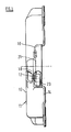
- the present invention provides a clutch assembly comprising a recessed cover member having a mounting flange for engagement with a flywheel, a pressure plate, flexible resilient means connecting outwardly directed lugs of the pressure plate to the cover member for torque transmission whilst permitting relative axial movement therebetween, spring means operative between the cover member and pressure plate to bias the pressure plate towards a position corresponding, when the assembly is in use, to the engaged position and stop means constituted by abutments on the cover arranged to engage directly with the lugs of the pressure plate for preventing movement of the pressure plate in a direction out of the recess to an extent which would over stress the flexible means, characterised in that the abutments are set back from the mounting flange towards the pressure plate.
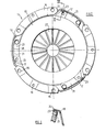
- the clutch is also provided with a conventional diaphragm spring 22 which acts between the cover and the pressure plate to urge the pressure plate in a direction out of the recess in the cover so that in use the pressure plate clamps a driven plate (not shown) between the pressure plate and an engine flywheel (not shown) on which the cover is mounted by flanges 14.
- the clutch is also provided with a release mechanism for removing the clamping force of the diaphragm spring on the pressure plate. Operation of the release mechanism removes the clamping load on the driven plate and so releases the clutch. The ensure positive release of the clutch, the leaf spring characteristics of the drive straps 21 are used to positively retract the pressure plate from the driven plate. Details of. the mounting of the diaphragm spring 22 and of the release mechanism are not shown or described in detail because they are entirely conventional and are not relevant to the invention.
Landscapes
- Engineering & Computer Science (AREA)
- General Engineering & Computer Science (AREA)
- Mechanical Engineering (AREA)
- Mechanical Operated Clutches (AREA)
- Power Steering Mechanism (AREA)
- Braking Arrangements (AREA)
Priority Applications (1)
| Application Number | Priority Date | Filing Date | Title |
|---|---|---|---|
| AT81302924T ATE16838T1 (de) | 1980-07-04 | 1981-06-29 | Reibungskupplung. |
Applications Claiming Priority (2)
| Application Number | Priority Date | Filing Date | Title |
|---|---|---|---|
| GB8022012 | 1980-07-04 | ||
| GB8022012 | 1980-07-04 |
Publications (2)
| Publication Number | Publication Date |
|---|---|
| EP0043683A1 true EP0043683A1 (de) | 1982-01-13 |
| EP0043683B1 EP0043683B1 (de) | 1985-12-04 |
Family
ID=10514548
Family Applications (1)
| Application Number | Title | Priority Date | Filing Date |
|---|---|---|---|
| EP81302924A Expired EP0043683B1 (de) | 1980-07-04 | 1981-06-29 | Reibungskupplung |
Country Status (5)
| Country | Link |
|---|---|
| US (1) | US4423804A (de) |
| EP (1) | EP0043683B1 (de) |
| JP (1) | JPS6024331B2 (de) |
| AT (1) | ATE16838T1 (de) |
| DE (1) | DE3173109D1 (de) |
Cited By (3)
| Publication number | Priority date | Publication date | Assignee | Title |
|---|---|---|---|---|
| FR2520823A1 (fr) * | 1982-02-04 | 1983-08-05 | Valeo | Mecanisme d'embrayage a friction muni d'un dispositif perfectionne de limitation de course, notamment pour vehicule automobile |
| FR2528926A1 (fr) * | 1982-06-21 | 1983-12-23 | Valeo | Procede de fabrication d'un mecanisme d'embrayage |
| GB2153456A (en) * | 1984-01-28 | 1985-08-21 | Fichtel & Sachs Ag | A friction clutch with tangential leaf springs |
Families Citing this family (5)
| Publication number | Priority date | Publication date | Assignee | Title |
|---|---|---|---|---|
| FR2547882B1 (fr) * | 1983-06-22 | 1986-02-07 | Valeo | Mecanisme d'embrayage notamment pour vehicule automobile |
| FR2554885B1 (fr) * | 1983-11-10 | 1990-06-01 | Automotive Products Plc | Dispositifs de fermeture d'embrayages a friction |
| FR2562619B1 (fr) * | 1984-04-04 | 1987-01-02 | Valeo | Mecanisme d'embrayage a butee de retenue pour le plateau de pression, notamment pour vehicule automobile |
| FR2564546B1 (fr) * | 1984-05-18 | 1989-06-09 | Valeo | Mecanisme d'embrayage a sens de rotation privilegie. |
| DE19825135C1 (de) * | 1998-06-05 | 1999-08-12 | Mannesmann Sachs Ag | Baueinheit für eine Reibungskupplung mit Montagehilfe und Transportsicherung |
Citations (2)
| Publication number | Priority date | Publication date | Assignee | Title |
|---|---|---|---|---|
| US2541611A (en) * | 1946-05-16 | 1951-02-13 | Borg Warner | Clutch release |
| GB2056591A (en) * | 1979-08-17 | 1981-03-18 | Fraymon Sa | Motor vehicle clutch mechanism |
Family Cites Families (7)
| Publication number | Priority date | Publication date | Assignee | Title |
|---|---|---|---|---|
| US3554342A (en) | 1968-12-23 | 1971-01-12 | Borg Warner | Torque transmitting device |
| DE2121919C3 (de) | 1971-05-04 | 1983-11-24 | LuK Lamellen und Kupplungsbau GmbH, 7580 Bühl | Reibungskupplung |
| US4069905A (en) | 1975-02-13 | 1978-01-24 | Societe Anonyme Francaise Du Ferodo | Assembly unit for a clutch, especially for the clutches of automobile vehicles |
| DE2607925A1 (de) | 1976-02-27 | 1977-09-01 | Luk Lamellen & Kupplungsbau | Reibungskupplung, insbesondere fuer kfz |
| US4062820A (en) | 1976-12-06 | 1977-12-13 | Emery Industries, Inc. | Thermoplastic reinforcing adhesives and substrates coated therewith |
| DE2824682A1 (de) | 1978-06-06 | 1979-12-20 | Luk Lamellen & Kupplungsbau | Verfahren und einrichtung zum betrieb einer brennkraftmaschine mit dieser nachgeschalteter schwungmasse |
| DE2841763A1 (de) * | 1978-09-26 | 1980-04-03 | Luk Lamellen & Kupplungsbau | Reibungskupplung sowie verfahren zur montage von reibungskupplungen |
-
1981
- 1981-06-29 AT AT81302924T patent/ATE16838T1/de not_active IP Right Cessation
- 1981-06-29 EP EP81302924A patent/EP0043683B1/de not_active Expired
- 1981-06-29 DE DE8181302924T patent/DE3173109D1/de not_active Expired
- 1981-07-02 US US06/279,651 patent/US4423804A/en not_active Expired - Fee Related
- 1981-07-04 JP JP56104950A patent/JPS6024331B2/ja not_active Expired
Patent Citations (2)
| Publication number | Priority date | Publication date | Assignee | Title |
|---|---|---|---|---|
| US2541611A (en) * | 1946-05-16 | 1951-02-13 | Borg Warner | Clutch release |
| GB2056591A (en) * | 1979-08-17 | 1981-03-18 | Fraymon Sa | Motor vehicle clutch mechanism |
Cited By (4)
| Publication number | Priority date | Publication date | Assignee | Title |
|---|---|---|---|---|
| FR2520823A1 (fr) * | 1982-02-04 | 1983-08-05 | Valeo | Mecanisme d'embrayage a friction muni d'un dispositif perfectionne de limitation de course, notamment pour vehicule automobile |
| FR2528926A1 (fr) * | 1982-06-21 | 1983-12-23 | Valeo | Procede de fabrication d'un mecanisme d'embrayage |
| US4562636A (en) * | 1982-06-21 | 1986-01-07 | Valeo | Clutch cover assembly manufacturing method |
| GB2153456A (en) * | 1984-01-28 | 1985-08-21 | Fichtel & Sachs Ag | A friction clutch with tangential leaf springs |
Also Published As
| Publication number | Publication date |
|---|---|
| DE3173109D1 (en) | 1986-01-16 |
| US4423804A (en) | 1984-01-03 |
| EP0043683B1 (de) | 1985-12-04 |
| JPS5743025A (en) | 1982-03-10 |
| ATE16838T1 (de) | 1985-12-15 |
| JPS6024331B2 (ja) | 1985-06-12 |
Similar Documents
| Publication | Publication Date | Title |
|---|---|---|
| JP3752642B2 (ja) | 摩擦トルク装置 | |
| US4122929A (en) | Friction clutch, especially for motor vehicles | |
| EP0043683B1 (de) | Reibungskupplung | |
| EP0114098B1 (de) | Reibungskupplung | |
| JPS599317A (ja) | クラツチ機構 | |
| US4332314A (en) | Spring clutch | |
| TW201937075A (zh) | 動力傳輸裝置 | |
| GB2032017A (en) | Friction clutch and process for the assembly of friction clutches | |
| JP2984655B2 (ja) | 自動式の損耗補償能力を有する摩擦クラッチ | |
| US4715484A (en) | Automatic intermediate plate positioner | |
| KR102396061B1 (ko) | 특히 자동차용의 클러치 장치용 어셈블리 | |
| CN111828509B (zh) | 制动衬片复位装置、制动衬片组件和车辆盘式制动器 | |
| US4607738A (en) | Friction clutch cover assemblies | |
| US5236070A (en) | Retracting strap plate clutch assembly | |
| WO2018109129A1 (en) | A torque limiter having a drive plate | |
| US6915889B2 (en) | Pressure plate assembly for a friction clutch | |
| US5265709A (en) | Pull-type clutch cover assembly | |
| AU8275287A (en) | Automatic adjusting device | |
| EP0032606A1 (de) | Reibungskupplung | |
| US5168974A (en) | Clutch mechanism, in particular for a motor vehicle | |
| CN112739925B (zh) | 具有用于防止反向驱动的耐磨特征部的离合器调节系统 | |
| US3667582A (en) | Radial spring clutch | |
| JPH08511332A (ja) | クラッチ機構、特に自動車用クラッチ機構 | |
| GB1592874A (en) | Clutch assemblies | |
| JP3515667B2 (ja) | クラッチカバー組立体 |
Legal Events
| Date | Code | Title | Description |
|---|---|---|---|
| PUAI | Public reference made under article 153(3) epc to a published international application that has entered the european phase |
Free format text: ORIGINAL CODE: 0009012 |
|
| AK | Designated contracting states |
Designated state(s): AT BE CH DE FR GB IT LI LU NL SE |
|
| 17P | Request for examination filed |
Effective date: 19820609 |
|
| ITF | It: translation for a ep patent filed | ||
| GRAA | (expected) grant |
Free format text: ORIGINAL CODE: 0009210 |
|
| AK | Designated contracting states |
Designated state(s): AT BE CH DE FR GB IT LI LU NL SE |
|
| REF | Corresponds to: |
Ref document number: 16838 Country of ref document: AT Date of ref document: 19851215 Kind code of ref document: T |
|
| REF | Corresponds to: |
Ref document number: 3173109 Country of ref document: DE Date of ref document: 19860116 |
|
| ET | Fr: translation filed | ||
| PGFP | Annual fee paid to national office [announced via postgrant information from national office to epo] |
Ref country code: AT Payment date: 19860613 Year of fee payment: 6 |
|
| PG25 | Lapsed in a contracting state [announced via postgrant information from national office to epo] |
Ref country code: LU Free format text: LAPSE BECAUSE OF NON-PAYMENT OF DUE FEES Effective date: 19860630 |
|
| PLBE | No opposition filed within time limit |
Free format text: ORIGINAL CODE: 0009261 |
|
| STAA | Information on the status of an ep patent application or granted ep patent |
Free format text: STATUS: NO OPPOSITION FILED WITHIN TIME LIMIT |
|
| 26N | No opposition filed | ||
| PGFP | Annual fee paid to national office [announced via postgrant information from national office to epo] |
Ref country code: NL Payment date: 19870630 Year of fee payment: 7 |
|
| REG | Reference to a national code |
Ref country code: GB Ref legal event code: 732 |
|
| PG25 | Lapsed in a contracting state [announced via postgrant information from national office to epo] |
Ref country code: AT Effective date: 19880629 |
|
| PG25 | Lapsed in a contracting state [announced via postgrant information from national office to epo] |
Ref country code: LI Effective date: 19880630 Ref country code: CH Effective date: 19880630 |
|
| BERE | Be: lapsed |
Owner name: LAYCOCK ENGINEERING LTD Effective date: 19880630 |
|
| PG25 | Lapsed in a contracting state [announced via postgrant information from national office to epo] |
Ref country code: NL Effective date: 19890101 |
|
| NLV4 | Nl: lapsed or anulled due to non-payment of the annual fee | ||
| REG | Reference to a national code |
Ref country code: CH Ref legal event code: PL |
|
| REG | Reference to a national code |
Ref country code: FR Ref legal event code: TP |
|
| ITPR | It: changes in ownership of a european patent |
Owner name: CESSIONE;LUK LAMELLEN UND KUPPLUNGSBAU GMBH |
|
| PG25 | Lapsed in a contracting state [announced via postgrant information from national office to epo] |
Ref country code: GB Effective date: 19890629 |
|
| PG25 | Lapsed in a contracting state [announced via postgrant information from national office to epo] |
Ref country code: SE Effective date: 19890630 Ref country code: BE Effective date: 19890630 |
|
| GBPC | Gb: european patent ceased through non-payment of renewal fee | ||
| PG25 | Lapsed in a contracting state [announced via postgrant information from national office to epo] |
Ref country code: FR Free format text: LAPSE BECAUSE OF NON-PAYMENT OF DUE FEES Effective date: 19900228 |
|
| PG25 | Lapsed in a contracting state [announced via postgrant information from national office to epo] |
Ref country code: DE Effective date: 19900301 |
|
| REG | Reference to a national code |
Ref country code: FR Ref legal event code: ST |
|
| EUG | Se: european patent has lapsed |
Ref document number: 81302924.6 Effective date: 19900412 |