EP0041876B1 - Fixation d'un réservoir à carburant en matière synthétique - Google Patents
Fixation d'un réservoir à carburant en matière synthétique Download PDFInfo
- Publication number
- EP0041876B1 EP0041876B1 EP81400662A EP81400662A EP0041876B1 EP 0041876 B1 EP0041876 B1 EP 0041876B1 EP 81400662 A EP81400662 A EP 81400662A EP 81400662 A EP81400662 A EP 81400662A EP 0041876 B1 EP0041876 B1 EP 0041876B1
- Authority
- EP
- European Patent Office
- Prior art keywords
- tank
- fixing
- cross
- vehicle
- fixing means
- Prior art date
- Legal status (The legal status is an assumption and is not a legal conclusion. Google has not performed a legal analysis and makes no representation as to the accuracy of the status listed.)
- Expired
Links
Images

Classifications
-
- B—PERFORMING OPERATIONS; TRANSPORTING
- B60—VEHICLES IN GENERAL
- B60K—ARRANGEMENT OR MOUNTING OF PROPULSION UNITS OR OF TRANSMISSIONS IN VEHICLES; ARRANGEMENT OR MOUNTING OF PLURAL DIVERSE PRIME-MOVERS IN VEHICLES; AUXILIARY DRIVES FOR VEHICLES; INSTRUMENTATION OR DASHBOARDS FOR VEHICLES; ARRANGEMENTS IN CONNECTION WITH COOLING, AIR INTAKE, GAS EXHAUST OR FUEL SUPPLY OF PROPULSION UNITS IN VEHICLES
- B60K15/00—Arrangement in connection with fuel supply of combustion engines or other fuel consuming energy converters, e.g. fuel cells; Mounting or construction of fuel tanks
- B60K15/03—Fuel tanks
- B60K15/063—Arrangement of tanks
- B60K15/067—Mounting of tanks
Definitions
- the present invention relates to a device for fixing a fuel tank made of synthetic material, in particular for motor vehicles.
- Plastic fuel tanks are most often fixed to the structure of a vehicle using two metal straps sheathed in rubber to avoid the aggressiveness of the metal on the tank.
- the above fixing is not very economical and penalizes the fixing function of such a tank compared to a sheet metal tank, which is carried out more simply by screws, washers and nuts.
- the tank when using a vehicle, the tank is subjected to vertical, transverse and longitudinal accelerations due to braking; it must therefore be held positively on the chassis, which is not enough the case according to the above device.
- the tank layout has been moved outside the engine compartment, and more particularly at the rear of the vehicle.
- the object of the present invention lies in a safe and economical solution for fixing a synthetic fuel tank installed by the lower and rear area of the vehicle.
- the front face of said plastic tank has protuberances which cooperate, following the forward movement of the tank, with the corresponding orifices located in a cross member of the chassis which faces it, while at at least one of the fixing lugs arranged laterally on the tank bears on the upper face of the horizontal wing of a side member of the vehicle constituted by an L-shaped section.
- the horizontal wings of said side members are cut so as to allow the passage of said tank fixing ears during its presentation. Then, the latter being pushed forward, against the cross member, said ears then rest on the upper face of the solid parts of the horizontal wings of the side members.
- only one of the ears of the tank rests on the upper face of the horizontal wing of the corresponding spar, while the fixing lug arranged on the opposite side is pressed against the lower face of the horizontal wing of the other spar.
- the reservoir in the fixed position, the reservoir is pressed against the cross member so as to create a slight stress between the protuberances and the corresponding receiving orifices of the cross member.
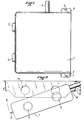
- the tank 1 of fig. 1 has a filling nozzle 2, at least one anterior protuberance such as 3 and lateral fixing ears 4 and 5, pierced with holes 6 and 7 for the passage of fixing means.
- the rear part of the chassis of the vehicle supporting the tank 1 has two longitudinal members 8-9 in L whose lower horizontal ends 10-11 are directed face to face, and joined transversely, towards the front of the vehicle, by a cross member 12 , having the right of the protrusions 3 of the reservoir, receiving orifices 13.
- the lower horizontal ends 10-11 of the longitudinal members are cut at 14-15, so as to allow the passage of the ears 4- 5 of the tank; the same is true at 16 of the vertical wall of the right side member for the introduction of the filling nozzle 2.
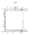
- the mounting of the reservoir 1 is carried out as shown in FIG. 2.
- the tank 1 is then pushed towards the front of the vehicle (left side of FIG. 3), so that the protrusions 3 fit into the orifices 13 of the crosspiece which face it.
- a complementary thrust of the reservoir is then exerted towards the front, to create a slight constraint on the protrusions 3 in the orifices 13, thus ensuring good maintenance of the assembly.
- the reservoir 1 its protrusions 3 built into complementary holes 13 formed in the cross member 12, its mounting lugs 4-5 cooperating with the lower horizontal ends 10-11 of the longitudinal members 8-9 in L, we end filling 2 introduced into passage 16 of the verticle face of the right side member.
- the difference between the tank assemblies according to fig. 3 and 4 is located at the level of the relative arrangement of the fixing lugs 4-5 and the lower ends 10-11 of the side members.
- the second fixing lug 5 comes into contact with the end 11 of the spar 9 through its lower part to which it is fixed.
- this operation occurs after creation of a certain embedding constraint between the protrusions 3 and the orifices 13 of the cross member 12. This final assembly is visible in FIG. 5.
- the invention will not be departed from by bringing minor variants to it, for example by changing the location of the openings in the longitudinal members or the number of fixing lugs, or that of the protrusions, etc.
Landscapes
- Engineering & Computer Science (AREA)
- Life Sciences & Earth Sciences (AREA)
- Sustainable Development (AREA)
- Sustainable Energy (AREA)
- Chemical & Material Sciences (AREA)
- Combustion & Propulsion (AREA)
- Transportation (AREA)
- Mechanical Engineering (AREA)
- Cooling, Air Intake And Gas Exhaust, And Fuel Tank Arrangements In Propulsion Units (AREA)
- Connection Of Plates (AREA)
Applications Claiming Priority (2)
| Application Number | Priority Date | Filing Date | Title |
|---|---|---|---|
| FR8012623 | 1980-06-06 | ||
| FR8012623A FR2483859A1 (fr) | 1980-06-06 | 1980-06-06 | Fixation d'un reservoir a carburant en matiere synthetique |
Publications (2)
| Publication Number | Publication Date |
|---|---|
| EP0041876A1 EP0041876A1 (fr) | 1981-12-16 |
| EP0041876B1 true EP0041876B1 (fr) | 1984-06-06 |
Family
ID=9242797
Family Applications (1)
| Application Number | Title | Priority Date | Filing Date |
|---|---|---|---|
| EP81400662A Expired EP0041876B1 (fr) | 1980-06-06 | 1981-04-28 | Fixation d'un réservoir à carburant en matière synthétique |
Country Status (6)
| Country | Link |
|---|---|
| US (1) | US4411441A (enExample) |
| EP (1) | EP0041876B1 (enExample) |
| DE (1) | DE3163960D1 (enExample) |
| ES (1) | ES267662Y (enExample) |
| FR (1) | FR2483859A1 (enExample) |
| PT (1) | PT73140B (enExample) |
Families Citing this family (14)
| Publication number | Priority date | Publication date | Assignee | Title |
|---|---|---|---|---|
| US4593786A (en) * | 1982-05-03 | 1986-06-10 | John Tate | Self-contained power supply and support therefor |
| US4540191A (en) * | 1984-03-12 | 1985-09-10 | Deere & Company | Static discharge prevention system for a largely non-metallic fuel tank |
| DE3423954C1 (de) * | 1984-06-29 | 1986-01-02 | Daimler-Benz Ag, 7000 Stuttgart | Kraftstofftankanordnung im Heckbereich eines Kraftwagens |
| JP2535338B2 (ja) * | 1986-12-02 | 1996-09-18 | 日産自動車株式会社 | キヤニスタの配置構造 |
| DE3733503C1 (de) * | 1987-10-03 | 1988-12-01 | Bayerische Motoren Werke Ag | Kraftstoffbehaelteranordnung fuer Kraftfahrzeuge,insbesondere Personenkraftwagen |
| AT389681B (de) * | 1988-06-22 | 1990-01-10 | Steyr Daimler Puch Ag | Fussboden fuer kraftfahrzeuge, insbesondere fahrerhausboden |
| US4895268A (en) * | 1988-08-17 | 1990-01-23 | Ford Motor Company | Method of making a hollow plastic article |
| US5221021A (en) * | 1991-12-16 | 1993-06-22 | Ford Motor Company | Fuel tank reservoir |
| IT1250543B (it) * | 1991-12-17 | 1995-04-08 | Fiat Auto Spa | Sistema di attacco di un serbatoio alla scocca di un veicolo, in particolare di un autoveicolo. |
| SE469377B (sv) * | 1991-12-23 | 1993-06-28 | Saab Scania Ab | Braenslebehaallararrangemang foer motorfordon |
| US7374208B2 (en) * | 2003-03-18 | 2008-05-20 | Kobelco Construction Machinery Co., Ltd. | Working machine |
| DE102007012948A1 (de) * | 2007-03-14 | 2008-09-18 | Erhard & Söhne GmbH | Kraftstoffbehälter |
| US7823568B1 (en) * | 2009-04-30 | 2010-11-02 | Ford Global Technologies | Evaporative emission control canister for automotive vehicle |
| CZ305012B6 (cs) | 2012-03-30 | 2015-03-25 | Zentiva, K.S. | Způsob přípravy skopinesteru kyseliny di(2-thienyl)glykolové, intermediátu v syntéze tiotropium bromidu |
Citations (3)
| Publication number | Priority date | Publication date | Assignee | Title |
|---|---|---|---|---|
| US1500646A (en) * | 1920-12-18 | 1924-07-08 | Willys Corp | Motor vehicle |
| FR1510002A (fr) * | 1966-12-02 | 1968-01-19 | Système accéléré de ravitaillement en carburant pour voitures automobiles, plus particulièrement de compétition | |
| GB1227897A (enExample) * | 1968-10-25 | 1971-04-07 |
Family Cites Families (3)
| Publication number | Priority date | Publication date | Assignee | Title |
|---|---|---|---|---|
| FR488886A (fr) * | 1917-09-12 | 1918-11-21 | Edward Hale Belden | Perfectionnements aux automobiles |
| DE2557967C3 (de) * | 1975-12-22 | 1978-12-14 | Daimler-Benz Ag, 7000 Stuttgart | Kühlerbefestigung eines Kraftfahrzeuges |
| US4234050A (en) * | 1978-11-01 | 1980-11-18 | Roper Corporation | Snow bob with detachable fuel tank |
-
1980
- 1980-06-06 FR FR8012623A patent/FR2483859A1/fr active Granted
-
1981
- 1981-04-28 DE DE8181400662T patent/DE3163960D1/de not_active Expired
- 1981-04-28 EP EP81400662A patent/EP0041876B1/fr not_active Expired
- 1981-06-02 ES ES1981267662U patent/ES267662Y/es not_active Expired
- 1981-06-04 PT PT73140A patent/PT73140B/pt unknown
- 1981-06-08 US US06/271,129 patent/US4411441A/en not_active Expired - Fee Related
Patent Citations (3)
| Publication number | Priority date | Publication date | Assignee | Title |
|---|---|---|---|---|
| US1500646A (en) * | 1920-12-18 | 1924-07-08 | Willys Corp | Motor vehicle |
| FR1510002A (fr) * | 1966-12-02 | 1968-01-19 | Système accéléré de ravitaillement en carburant pour voitures automobiles, plus particulièrement de compétition | |
| GB1227897A (enExample) * | 1968-10-25 | 1971-04-07 |
Also Published As
| Publication number | Publication date |
|---|---|
| FR2483859A1 (fr) | 1981-12-11 |
| PT73140A (fr) | 1981-07-01 |
| FR2483859B1 (enExample) | 1984-08-03 |
| EP0041876A1 (fr) | 1981-12-16 |
| ES267662Y (es) | 1983-10-16 |
| US4411441A (en) | 1983-10-25 |
| ES267662U (es) | 1983-04-01 |
| PT73140B (fr) | 1982-07-01 |
| DE3163960D1 (en) | 1984-07-12 |
Similar Documents
| Publication | Publication Date | Title |
|---|---|---|
| EP0041876B1 (fr) | Fixation d'un réservoir à carburant en matière synthétique | |
| EP2595857B1 (fr) | Chassis de vehicule automobile avec piece de fixation d'elements de carrosserie et de cables electriques au plancher central | |
| FR2858798A1 (fr) | Traverse de face avant technique d'un vehicule automobile, face avant technique et support de module de refroidissement munis d'une telle traverse | |
| EP3126209B1 (fr) | Structure de vehicule automobile renforcee | |
| FR2924085A1 (fr) | Dispositif et procede de fixation d'un ensemble d'aile sur une paroi de caisse d'un vehicule automobile | |
| FR3088611A1 (fr) | Element structurel lacunaire pour planche de bord, traverse associee et planche de bord correspondante | |
| FR2932766A1 (fr) | Element de support de peau de bouclier ameliore pour vehicule automobile | |
| EP3259173B1 (fr) | Renfort pour structure de caisse de véhicule automobile | |
| FR3099907A1 (fr) | Déflecteur aérodynamique arrière pour véhicule automobile | |
| FR3119826A1 (fr) | Ensemble comprenant un élément de carénage destiné à être monté sous caisse dans un véhicule automobile, et au moins une pièce de fixation de l’élément de carénage | |
| EP3154826B1 (fr) | Agencement d'un élément de garniture de planche de bord d'un véhicule automobile sur un élément de support de cette planche de bord | |
| FR2914618A1 (fr) | Procede de montage d'un element de soubassement transversal et d'une face avant technique | |
| FR3125630A1 (fr) | Support de boitier a fusibles pour vehicule | |
| EP1758767A1 (fr) | Bloc projecteur pour véhicule automobile | |
| EP3853109B1 (fr) | Vehicule automobile comprenant des moyens d'accrochage sous le plancher arriere pour limiter l'enfoncement en cas de choc | |
| FR3127177A1 (fr) | Pare-chocs à armature à patte anti-affaissement, pour un véhicule terrestre | |
| FR3103450A1 (fr) | Dispositif de protection de la batterie de traction des vehicules electriques | |
| EP3812219B1 (fr) | Ensemble de batterie comportant un panneau d absorption acoustique et procédé d'équipement d'un ensemble batterie avec un tel panneau | |
| FR2711596A1 (fr) | Dispositif pare-chocs de véhicule automobile. | |
| FR2459148A2 (fr) | Dispositif d'attelage de remorques a des vehicules tracteurs | |
| FR3153297A1 (fr) | Ensemble pour soutien d’un bouclier d’un véhicule automobile. | |
| FR3062840A1 (fr) | Caisse de vehicule automobile comprenant une piece de renfort, et vehicule automobile comprenant une telle caisse | |
| EP3385150B1 (fr) | Renforcement de plancher de véhicule en cas de choc frontal à faible recouvrement | |
| FR3153798A1 (fr) | Plancher de véhicule, adapté à l’appui d’une jambe de force d’un siège pour enfant | |
| EP4359285A1 (fr) | Cloison de longeron et caisse de véhicule automobile équipée d'une telle cloison de longeron |
Legal Events
| Date | Code | Title | Description |
|---|---|---|---|
| PUAI | Public reference made under article 153(3) epc to a published international application that has entered the european phase |
Free format text: ORIGINAL CODE: 0009012 |
|
| 17P | Request for examination filed |
Effective date: 19810721 |
|
| AK | Designated contracting states |
Designated state(s): BE DE GB IT NL SE |
|
| ITF | It: translation for a ep patent filed | ||
| GRAA | (expected) grant |
Free format text: ORIGINAL CODE: 0009210 |
|
| AK | Designated contracting states |
Designated state(s): BE DE GB IT NL SE |
|
| REF | Corresponds to: |
Ref document number: 3163960 Country of ref document: DE Date of ref document: 19840712 |
|
| PLBE | No opposition filed within time limit |
Free format text: ORIGINAL CODE: 0009261 |
|
| STAA | Information on the status of an ep patent application or granted ep patent |
Free format text: STATUS: NO OPPOSITION FILED WITHIN TIME LIMIT |
|
| 26N | No opposition filed | ||
| PGFP | Annual fee paid to national office [announced via postgrant information from national office to epo] |
Ref country code: SE Payment date: 19900319 Year of fee payment: 10 |
|
| PGFP | Annual fee paid to national office [announced via postgrant information from national office to epo] |
Ref country code: BE Payment date: 19900323 Year of fee payment: 10 |
|
| PGFP | Annual fee paid to national office [announced via postgrant information from national office to epo] |
Ref country code: DE Payment date: 19900327 Year of fee payment: 10 |
|
| PGFP | Annual fee paid to national office [announced via postgrant information from national office to epo] |
Ref country code: GB Payment date: 19900331 Year of fee payment: 10 |
|
| ITTA | It: last paid annual fee | ||
| PGFP | Annual fee paid to national office [announced via postgrant information from national office to epo] |
Ref country code: NL Payment date: 19900430 Year of fee payment: 10 |
|
| PG25 | Lapsed in a contracting state [announced via postgrant information from national office to epo] |
Ref country code: GB Effective date: 19910428 |
|
| PG25 | Lapsed in a contracting state [announced via postgrant information from national office to epo] |
Ref country code: SE Effective date: 19910429 |
|
| PG25 | Lapsed in a contracting state [announced via postgrant information from national office to epo] |
Ref country code: BE Effective date: 19910430 |
|
| BERE | Be: lapsed |
Owner name: REGIE NATIONALE DES USINES RENAULT Effective date: 19910430 |
|
| PG25 | Lapsed in a contracting state [announced via postgrant information from national office to epo] |
Ref country code: NL Effective date: 19911101 |
|
| NLV4 | Nl: lapsed or anulled due to non-payment of the annual fee | ||
| GBPC | Gb: european patent ceased through non-payment of renewal fee | ||
| PG25 | Lapsed in a contracting state [announced via postgrant information from national office to epo] |
Ref country code: DE Effective date: 19920201 |
|
| EUG | Se: european patent has lapsed |
Ref document number: 81400662.3 Effective date: 19911108 |