EP0041104B1 - Corona discharge device for electrophotographic apparatus - Google Patents
Corona discharge device for electrophotographic apparatus Download PDFInfo
- Publication number
- EP0041104B1 EP0041104B1 EP81101822A EP81101822A EP0041104B1 EP 0041104 B1 EP0041104 B1 EP 0041104B1 EP 81101822 A EP81101822 A EP 81101822A EP 81101822 A EP81101822 A EP 81101822A EP 0041104 B1 EP0041104 B1 EP 0041104B1
- Authority
- EP
- European Patent Office
- Prior art keywords
- housing
- corona
- wire
- stub member
- stub
- Prior art date
- Legal status (The legal status is an assumption and is not a legal conclusion. Google has not performed a legal analysis and makes no representation as to the accuracy of the status listed.)
- Expired
Links
- 238000005452 bending Methods 0.000 claims description 2
- 238000000034 method Methods 0.000 description 3
- 238000007792 addition Methods 0.000 description 1
- 238000004140 cleaning Methods 0.000 description 1
- 238000011109 contamination Methods 0.000 description 1
- 239000000428 dust Substances 0.000 description 1
- 150000002500 ions Chemical class 0.000 description 1
- 238000004519 manufacturing process Methods 0.000 description 1
- 239000000463 material Substances 0.000 description 1
- 230000007246 mechanism Effects 0.000 description 1
- 238000012986 modification Methods 0.000 description 1
- 230000004048 modification Effects 0.000 description 1
- 238000000465 moulding Methods 0.000 description 1
- 239000002245 particle Substances 0.000 description 1
- 230000000717 retained effect Effects 0.000 description 1
Images
Classifications
-
- H—ELECTRICITY
- H01—ELECTRIC ELEMENTS
- H01T—SPARK GAPS; OVERVOLTAGE ARRESTERS USING SPARK GAPS; SPARKING PLUGS; CORONA DEVICES; GENERATING IONS TO BE INTRODUCED INTO NON-ENCLOSED GASES
- H01T19/00—Devices providing for corona discharge
-
- G—PHYSICS
- G03—PHOTOGRAPHY; CINEMATOGRAPHY; ANALOGOUS TECHNIQUES USING WAVES OTHER THAN OPTICAL WAVES; ELECTROGRAPHY; HOLOGRAPHY
- G03G—ELECTROGRAPHY; ELECTROPHOTOGRAPHY; MAGNETOGRAPHY
- G03G15/00—Apparatus for electrographic processes using a charge pattern
- G03G15/02—Apparatus for electrographic processes using a charge pattern for laying down a uniform charge, e.g. for sensitising; Corona discharge devices
- G03G15/0291—Apparatus for electrographic processes using a charge pattern for laying down a uniform charge, e.g. for sensitising; Corona discharge devices corona discharge devices, e.g. wires, pointed electrodes, means for cleaning the corona discharge device
Definitions
- This invention generally relates to corona discharge devices for electrophotographic apparatus, and more particularly to adjusting mechanisms therefor.
- electrophotographic copiers comprise a photoconductive surface which is initially charged uniformly by a corona charging apparatus, and then exposed to a light pattern representing the image to be copied. This produces a latent electrostatic image on the photoconductive surface. The image is next developed and then transferred to paper where the transfer is fixed to render the copy permanent.
- a corona charging apparatus is often used for the transfer operation, and photoconductive surface cleaning function.
- a corona charging apparatus comprises an elongated housing having a corona bay therein, and a corona wire or wires within the bay.
- the corona charging apparatus uniformly charge the photoconductive surface at a suitable voltage level.
- a major cause of nonuniform charge is variation in the distance between the photoconductive surface and the corona electrode within the corona charging apparatus. Such variation is due to a number of factors including a change in the positions of parts with use.
- U.S. Patent Specification No. 4,089,600 describes a corona electrode adjuster which employs a set screw threaded through one leg of an L-shaped member, the other leg of which has a notch which engages the corona electrode. Turning the set screw moves the L-shaped member, and the engaged corona electrode.
- This corona electrode adjuster requires at least two parts (i.e., the set screw and the L-shaped member) and requires their alignment before assembly in the corona charging apparatus.
- It is an object of the invention is to provide a corona electrode adjuster which employs fewer parts than the prior arrangements and permits easier adjustment of the electrode.
- a corona discharge device for electrophotographic apparatus comprising an elongated box-like open housing, a corona wire mounted in and passing along the housing and means for adjusting the position of the wire with respect to the housing characterised in that the adjusting means includes a stub member passing into the housing through a wall of the housing opposite the opening therein and mounted to this wall for rotational, but substantially no axial, movement, said stub member having a thread portion directly engaging the wire to cause movement of the wire in the axial direction of the stub upon rotation thereof.
- a corona discharge device for electrophotographic apparatus comprising an elongated box-like open housing, a corona element mounted in, and passing along, the housing, and means for adjusting the position of the element with respect to the housing, characterised in that the corona element includes a corona wire mounted under tension between a flat flexible strip connector at one end and a tensioning spring at the opposite end and the adjusting means includes a stub member passing into the housing through a wall of the housing opposite the opening therein and mounted to this wall for rotational, but substantially no axial, movement, said stub member having a thread portion directly engaging the connector to cause bending of the connector in the axial direction of the stub member upon rotation thereof.
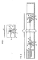
- corona charging apparatus 10 comprises an elongated housing 11 (only a portion of which is shown), having a corona bay 12 therein.
- Corona wire 13 (only a portion of which is shown) extends substantially along the length of the bay.
- corona wire 13 When suitably energized by means not shown, corona wire 13 emits ions which charge photoconductive surface 14.
- a corona wire adjuster promotes uniform charging by enabling adjustment of the corona wire, to vary the distance between corona wire 13 and photoconductive surface 14.
- the corona wire adjuster employs a screw- like insulating stub member 16, which includes a slotted head 17 and a shank 18 with a spiral thread 22 thereon and a circular lip 19, having a larger diameter than that of shank 18.
- Stub member 16 is mounted on housing 11 in mounting hole 21 and retained in place axially by head 17 and lip 19 so that it may be rotated about its axis by a screwdriver or other appropriate tool, but with substantially no other movement relative to frame 11.
- the distance between head 17 and lip 19 is essentially the thickness of housing 11 at mounting hole 21. Since the diameter of shank 18 is substantially the diameter of mounting hole 21, once stub member 16 is snapped into place within mounting hole 21, it may be rotated within mounting hole 21 without movement in a vertical direction.
- Stub member 16 may be made of a plastic material, by using a low cost moulding process.
- the design and fabrication of lip 19 is such as to permit snapping stub member 16 in place into mounting hole 21.
- This technique is well known to persons having ordinary skill in this art.
- lip 19 may be a snap-on washer or the like, separate from but attachable to stub member 16.
- helical thread 22 may have a larger diameter than shank 18 and thus hold stub member 16 in place in mounting hole 21.
- corona wire 13 rides thread 22 and moves axially along shank 18. Accordingly, corona wire 13 moves closer to or further from photoconductive surface 14 depending upon the direction of rotation of stub member 16.
- corona wire adjuster provides for simple screwdriver adjustment. Only a single part, i.e., stub member 16, is used, in Fig. 1, and this part may be inexpensively moulded of low cost plastic. Assembly is simple, with stub member 16 merely snapping into place at mounting hole 21. Adjustment to a nominal or reference position, as would be necessary with a set screw, is unnecessary.
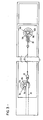
- FIG. 2 The use of a corona wire adjuster in a second corona charging apparatus is illustrated in Fig. 2.
- a pair of stub members, 16a and 16b, are employed at opposite ends of housing 11.
- the configuration and mounting of each of the stub members 16a and 16b are exactly as described with regard to the stub member in Fig. 1. It will be noted that access to the slotted heads 17a, 17b of stub members 16a, 16b, respectively, is on the outside of housing 11, i.e., on that side of the housing not adjacent photoconductive surface 14. This avoids exposure of the user to high voltage of the corona wire and allows access to the corona wire adjuster without the necessity of moving housing 11.
- the corona charging apparatus includes certain auxiliary elements which are attached to either end of corona wire 13 and which serve various purposes in the corona charging circuit.
- Auxiliary element 24 is a flexible elongated electrical connector which connects corona wire 13 to a source of electrical power (not shown).
- Element 25 is a coil spring for maintaining corona wire 13 taut.
- auxiliary elements 24 and 25 merely act as physical extensions of the corona wire. It will be understood that operation of the corona wire adjuster is the same whether the threads engage the corona wire itself, or an extension thereof, as represented by an auxiliary element.
- stub member 16b also serves as the terminating support for one end of corona wire 13, or the extension thereof represented by coil spring 25. This is accomplished by wrapping the end of coil spring 25 around shank 18b, in engagement with threads 22b. Stub member 16b thus serves to adjust corona wire 13 and also to support corona wire 13 within channel 12. Alternatively, a stub member may only be employed to adjust corona wire 13, as exemplified by stub member 1 6a. Separate support means for the corona wire must then be provided.
- Fig. 3 is a top view of the embodiment of Fig. 2. For clarity, photoconductive surface 14 is not shown. It will be seen that stub members 16a and 16b are positioned differently in order to centre the entire length of corona wire 13. within bay 12. Threads 19a of stub member 16a engage the side edge of flexible elongated connector 24. Stub member 16a is therefore positioned slightly off-centre in bay 12. For stub member 16b, the end of spring 25 is wrapped around shank 18b in engagement with threads 19b. Stub member 16b is therefore centred in bay 12.
- the corona charging apparatus can be structured with multiple side-by-side bays contained in a common housing with any or all of these bays having one or more corona wires positioned therein and including a corona wire adjuster of the type shown in Figs. 1 to 3.
- the corona bays can open directly toward the photoconductive surface or a grid screen or the like can be positioned across the bay opening between the corona wire and the photoconductive surface, or any combination can be used in a multiple bay corona arrangement.
- a multiple bay corona charging apparatus was built with three bays in a common housing, the centre bay having two corona wires mounted therein while the adjoining bays each had a single wire.
- a control grid screen covered the centre and one outer bay opening whereas the other outer bay opening was uncovered.
- the present arrangement is especially advantageous in a corona charging apparatus having multiple corona bays in a common housing in that it allows independent adjustment of each corona wire without disturbing the adjustment of any other corona wire within the housing.
Landscapes
- Physics & Mathematics (AREA)
- Engineering & Computer Science (AREA)
- Plasma & Fusion (AREA)
- General Physics & Mathematics (AREA)
- Electrostatic Charge, Transfer And Separation In Electrography (AREA)
Applications Claiming Priority (2)
| Application Number | Priority Date | Filing Date | Title |
|---|---|---|---|
| US06/154,734 US4320957A (en) | 1980-05-30 | 1980-05-30 | Corona wire adjuster |
| US154734 | 1993-11-17 |
Publications (3)
| Publication Number | Publication Date |
|---|---|
| EP0041104A2 EP0041104A2 (en) | 1981-12-09 |
| EP0041104A3 EP0041104A3 (en) | 1982-01-13 |
| EP0041104B1 true EP0041104B1 (en) | 1984-02-15 |
Family
ID=22552547
Family Applications (1)
| Application Number | Title | Priority Date | Filing Date |
|---|---|---|---|
| EP81101822A Expired EP0041104B1 (en) | 1980-05-30 | 1981-03-12 | Corona discharge device for electrophotographic apparatus |
Country Status (4)
| Country | Link |
|---|---|
| US (1) | US4320957A (cg-RX-API-DMAC10.html) |
| EP (1) | EP0041104B1 (cg-RX-API-DMAC10.html) |
| JP (1) | JPS5710159A (cg-RX-API-DMAC10.html) |
| DE (1) | DE3162205D1 (cg-RX-API-DMAC10.html) |
Families Citing this family (20)
| Publication number | Priority date | Publication date | Assignee | Title |
|---|---|---|---|---|
| US4469428A (en) * | 1981-08-08 | 1984-09-04 | Mita Industrial Co., Ltd. | Corona discharging apparatus used in an electrostatic photographic copying machine |
| US4442356A (en) * | 1981-08-21 | 1984-04-10 | International Business Machines Corporation | Corona wire assembly and method |
| JPS58126544A (ja) * | 1981-12-23 | 1983-07-28 | Toshiba Corp | 画像形成装置におけるコロナ放電装置 |
| JPS58190965A (ja) * | 1982-04-30 | 1983-11-08 | Canon Inc | 感光体ユニット及びこの感光体ユニットが着脱可能な画像形成装置 |
| US4575221A (en) * | 1982-05-20 | 1986-03-11 | Canon Kabushiki Kaisha | Process kit and an image forming apparatus using the same |
| JPH046030Y2 (cg-RX-API-DMAC10.html) * | 1986-05-16 | 1992-02-19 | ||
| US4764675A (en) * | 1987-10-22 | 1988-08-16 | Xerox Corporation | Self-tensioning coronode structure |
| JP3072112B2 (ja) * | 1990-03-02 | 2000-07-31 | 株式会社リコー | 画像形成装置 |
| US5181069A (en) * | 1990-07-23 | 1993-01-19 | Station Eight, Inc. | Method and apparatus for rewiring corona wire cartridge |
| US5140367A (en) * | 1990-07-23 | 1992-08-18 | Station Eight, Inc. | Method and apparatus for rewiring corona wire cartridge |
| US5339137A (en) * | 1992-09-17 | 1994-08-16 | Mita Industrial Co., Ltd. | Image forming apparatus |
| US5324941A (en) * | 1993-01-05 | 1994-06-28 | Xerox Corporation | Tension support mounting for a corona generating device |
| JP3302252B2 (ja) * | 1996-03-13 | 2002-07-15 | 京セラミタ株式会社 | 帯電装置 |
| US5897238A (en) * | 1998-06-18 | 1999-04-27 | Eastman Kodak Company | Method of setting position of a corona charger |
| US6303933B1 (en) * | 1999-03-26 | 2001-10-16 | Nexpress Solutions Llc | Apparatus and method of attaching corona wire to corona charger housing |
| US6366753B1 (en) * | 1999-11-11 | 2002-04-02 | Heidelberger Druckmaschinen Ag | Charger wire tensioning mounting mechanism and method of using |
| US6740878B2 (en) * | 2000-05-01 | 2004-05-25 | Xerox Corporation | System and method for automatically tensioning wires and for retaining tensioned wires under tension |
| US6900436B1 (en) | 2000-10-14 | 2005-05-31 | Eastman Kodak Company | Corona wire tensioning mechanism |
| JP4833885B2 (ja) * | 2006-04-21 | 2011-12-07 | 株式会社リコー | コロナワイヤカートリッジ、コロナ放電器、及びそれを用いた画像形成装置 |
| US7763853B2 (en) * | 2007-05-22 | 2010-07-27 | Xerox Corporation | Dicorotron having adjustable wire height |
Family Cites Families (9)
| Publication number | Priority date | Publication date | Assignee | Title |
|---|---|---|---|---|
| US3499143A (en) * | 1968-05-21 | 1970-03-03 | Pitney Bowes Inc | Electrostatic charger with resuppliable corona wire |
| US4089600A (en) * | 1970-03-11 | 1978-05-16 | Canon Kabushiki Kaisha | Corona discharge device for electrophotographic copying machine |
| JPS4937541B1 (cg-RX-API-DMAC10.html) * | 1970-12-30 | 1974-10-09 | ||
| US3922548A (en) * | 1973-05-18 | 1975-11-25 | Rank Xerox Ltd | Corona charging device and support arrangement |
| US4099219A (en) * | 1976-12-17 | 1978-07-04 | Xerox Corporation | Coronode tensioning and support arrangement |
| US4112298A (en) * | 1977-03-31 | 1978-09-05 | Xerox Corporation | Corona wire mounting means |
| JPS53143334A (en) * | 1977-05-20 | 1978-12-13 | Ricoh Co Ltd | Corona electrifier for transfer |
| JPS5922938B2 (ja) * | 1977-06-09 | 1984-05-30 | キヤノン株式会社 | コロナ放電器 |
| US4252431A (en) * | 1979-10-01 | 1981-02-24 | Nashua Corporation | Adjustable corona support |
-
1980
- 1980-05-30 US US06/154,734 patent/US4320957A/en not_active Expired - Lifetime
-
1981
- 1981-03-12 EP EP81101822A patent/EP0041104B1/en not_active Expired
- 1981-03-12 DE DE8181101822T patent/DE3162205D1/de not_active Expired
- 1981-04-10 JP JP5305481A patent/JPS5710159A/ja active Granted
Also Published As
| Publication number | Publication date |
|---|---|
| DE3162205D1 (en) | 1984-03-22 |
| EP0041104A3 (en) | 1982-01-13 |
| JPS5710159A (en) | 1982-01-19 |
| EP0041104A2 (en) | 1981-12-09 |
| US4320957A (en) | 1982-03-23 |
| JPS6146828B2 (cg-RX-API-DMAC10.html) | 1986-10-16 |
Similar Documents
| Publication | Publication Date | Title |
|---|---|---|
| EP0041104B1 (en) | Corona discharge device for electrophotographic apparatus | |
| JPS58126544A (ja) | 画像形成装置におけるコロナ放電装置 | |
| JPS6314176A (ja) | 制御スクリ−ン付コロナ放電装置 | |
| US4491407A (en) | Toner image transfer system | |
| US4335420A (en) | Corona discharge device | |
| JPH01136173A (ja) | 自己張力付与機構を備えたコロナ帯電装置 | |
| US3937960A (en) | Charging device for electrophotography | |
| US4322156A (en) | Charging apparatus for copying machine | |
| EP0606138B1 (en) | Tension support mounting for a corona generating device | |
| EP0465125B1 (en) | Corotron restringing tool | |
| US5909608A (en) | Tension support mounting for a corona generating device | |
| US4908513A (en) | Charging apparatus | |
| US4734722A (en) | Ion generator structure | |
| JPH06222652A (ja) | 一様な電荷ポテンシャルを付着するための調整可能なスコロトロン | |
| US4469428A (en) | Corona discharging apparatus used in an electrostatic photographic copying machine | |
| US5796103A (en) | Charging device and design method thereof | |
| US3068356A (en) | Xerographic charging apparatus | |
| JPH0114586B2 (cg-RX-API-DMAC10.html) | ||
| US5666601A (en) | Resistive ion source charging device | |
| JP3000732B2 (ja) | コロナ放電装置 | |
| KR890007206Y1 (ko) | 전자 사진 복사기의 대전 장치 | |
| JPS61151669A (ja) | 帯電装置 | |
| JPS60158583A (ja) | スクリーン付コロナ帯電装置 | |
| JPS5850345Y2 (ja) | 感光スクリ−ンの支持体 | |
| JPH04179087A (ja) | コロナ放電装置 |
Legal Events
| Date | Code | Title | Description |
|---|---|---|---|
| PUAI | Public reference made under article 153(3) epc to a published international application that has entered the european phase |
Free format text: ORIGINAL CODE: 0009012 |
|
| PUAL | Search report despatched |
Free format text: ORIGINAL CODE: 0009013 |
|
| AK | Designated contracting states |
Designated state(s): DE FR GB |
|
| AK | Designated contracting states |
Designated state(s): DE FR GB |
|
| 17P | Request for examination filed |
Effective date: 19820210 |
|
| GRAA | (expected) grant |
Free format text: ORIGINAL CODE: 0009210 |
|
| AK | Designated contracting states |
Designated state(s): DE FR GB |
|
| REF | Corresponds to: |
Ref document number: 3162205 Country of ref document: DE Date of ref document: 19840322 |
|
| ET | Fr: translation filed | ||
| PLBE | No opposition filed within time limit |
Free format text: ORIGINAL CODE: 0009261 |
|
| STAA | Information on the status of an ep patent application or granted ep patent |
Free format text: STATUS: NO OPPOSITION FILED WITHIN TIME LIMIT |
|
| 26N | No opposition filed | ||
| PGFP | Annual fee paid to national office [announced via postgrant information from national office to epo] |
Ref country code: GB Payment date: 19910220 Year of fee payment: 11 |
|
| PGFP | Annual fee paid to national office [announced via postgrant information from national office to epo] |
Ref country code: FR Payment date: 19910225 Year of fee payment: 11 |
|
| PGFP | Annual fee paid to national office [announced via postgrant information from national office to epo] |
Ref country code: DE Payment date: 19910323 Year of fee payment: 11 |
|
| PG25 | Lapsed in a contracting state [announced via postgrant information from national office to epo] |
Ref country code: GB Effective date: 19920312 |
|
| GBPC | Gb: european patent ceased through non-payment of renewal fee | ||
| PG25 | Lapsed in a contracting state [announced via postgrant information from national office to epo] |
Ref country code: FR Effective date: 19921130 |
|
| PG25 | Lapsed in a contracting state [announced via postgrant information from national office to epo] |
Ref country code: DE Effective date: 19921201 |
|
| REG | Reference to a national code |
Ref country code: FR Ref legal event code: ST |