EP0039056A1 - Method of and apparatus for producing vacuum skin packages - Google Patents
Method of and apparatus for producing vacuum skin packages Download PDFInfo
- Publication number
- EP0039056A1 EP0039056A1 EP81103098A EP81103098A EP0039056A1 EP 0039056 A1 EP0039056 A1 EP 0039056A1 EP 81103098 A EP81103098 A EP 81103098A EP 81103098 A EP81103098 A EP 81103098A EP 0039056 A1 EP0039056 A1 EP 0039056A1
- Authority
- EP
- European Patent Office
- Prior art keywords
- web
- vacuum chamber
- lower web
- upper web
- packaged goods
- Prior art date
- Legal status (The legal status is an assumption and is not a legal conclusion. Google has not performed a legal analysis and makes no representation as to the accuracy of the status listed.)
- Granted
Links
Images


Classifications
-
- B—PERFORMING OPERATIONS; TRANSPORTING
- B65—CONVEYING; PACKING; STORING; HANDLING THIN OR FILAMENTARY MATERIAL
- B65B—MACHINES, APPARATUS OR DEVICES FOR, OR METHODS OF, PACKAGING ARTICLES OR MATERIALS; UNPACKING
- B65B11/00—Wrapping, e.g. partially or wholly enclosing, articles or quantities of material, in strips, sheets or blanks, of flexible material
- B65B11/50—Enclosing articles, or quantities of material, by disposing contents between two sheets, e.g. pocketed sheets, and securing their opposed free margins
- B65B11/52—Enclosing articles, or quantities of material, by disposing contents between two sheets, e.g. pocketed sheets, and securing their opposed free margins one sheet being rendered plastic, e.g. by heating, and forced by fluid pressure, e.g. vacuum, into engagement with the other sheet and contents, e.g. skin-, blister-, or bubble- packaging
Definitions
- the invention relates to a method and a device for producing vacuum skin packaging according to the preamble of claim 1 and claim 4.
- the invention has for its object to provide a method by which an airtight skin Ver even with packaged goods of great height Pack can be made, and to provide an apparatus for performing the method.
- contour sealing makes better use of the size of the webs, ie the packaged goods can be larger in relation to the dimensions of the webs be than in pure F lächenêtelung. While there must be an edge of at least 20 mm around the packaged goods for surface sealing, it is sufficient in the method according to the invention to provide an edge of about 10 mm.
- the time required for a packaging cycle can be reduced by preheating the top web before loading the packaged goods. In a cyclical process, this preheating can take place while the previous skin packaging is being produced.
- the heating of the lower web can take place during the extraction of air between the webs.
- air pressure is preferably first applied to the upper web and then to the lower web on the side facing away from the packaged goods in order to counter the webs To press packaged goods.
- the web it is advisable not only to guide the top web, but also the bottom web, through conveyor chains at the lateral edges.
- the lower web is guided right up to the vacuum chamber.
- the vacuum skin packaging is moved out of the vacuum chamber by the guide chain of the upper web and thereby pulls the lower web. If the lower web is guided through its own guide chains right up to the vacuum chamber, only little force is exerted on the sealing seams by the redrawn lower web.
- the air between the webs is drawn off in the vacuum chamber. Precautions must be taken to ensure that the webs do not touch and stick together when they are introduced into the vacuum chamber. This is preferably achieved by the webs entering the vacuum chamber at an acute angle to one another and only touching at the end of the vacuum chamber.
- a height-adjustable sealing plate is preferably arranged in the lower part of the vacuum chamber.After closing the vacuum chamber, it is initially in its deep position of a few millimeters below the opening edge of the lower part, so that a corresponding gap remains between the webs through which the air can be extracted. After the air has been drawn off and approximately at the same time as the outside air has been let into the upper part, the sealing plate is raised and seals the two webs between itself and the sealing rubber at the opening edge of the upper part. So that the packaged goods run smoothly into the vacuum chamber on the lower web, a fabric band is preferably stretched over the lower part, which supports the lower web on its way through the vacuum chamber and prevents the lower web and the packaged goods lying directly on the heated sealing plate.
- the guide chain links are deflected downwards by chain wheels.
- the driver tabs are preferably tilted away to the side so that they cannot come into contact with the side edges of the lower web when the conveyor chains are deflected.
- the sideways tilting of the carrier plates is achieved in that the carrier plates run onto a conical lifting ring arranged centrally to the chain wheel.
- the packaging consists of an upper web 1 and a lower web 2, which are sealed together.
- the webs consist of thermoplastic films, in particular films of thermoplastic ionomer resins based on crosslinked ethylene copolymers, as are known under the trade name Surlyn.
- the lower web 2 can, however, also consist of cardboard or another rigid material which has a coating of a thermoplastic material and is therefore heat-sealable with the upper web 1.
- the sealing of the webs consists of a surface sealing and an additional sealing produced by pressure and heat in a narrow edge strip 20, which is referred to here as contour sealing.
- Such folds 21 are sealed at the edge of the pack by the additional contour sealing.
- the vacuum skin pack is produced in such a way that the packaged goods 5 are placed on the lower web 2 and the already pre-heated upper web 1 above the packaged goods 5 is arranged.
- the air is drawn off between the webs and around the packaged goods 5 and at the same time the lower web 2 is heated to the extent that it is plastic.
- the contour is then sealed by mechanical pressure in the narrow edge strip 20 and the top web 1 is placed against the packaged goods 5 and against the bottom web 2 by air pressure on the outside of the top web 1.
- the edge strip 20 extends around the entire package.
- the pack 3 can then be separated from the webs and any edge parts of the webs outside the edge strip 20 can be cut off.
- top web 1 and the bottom web 2 are heated and the pressure exerted on the edge strip 20 depend on the film material and its thickness.
- the top web is heated to a temperature of about 100 ° C and the bottom web is heated by contact with a sealing plate heated to about 90 ° C.
- the pressure exerted in the edge strip 20 is of the order of magnitude of 200 N / cm 2 . This pressure is applied for about 1 second.
- the lower web 2 is guided laterally by guide chains 4 over a table 22 on which the packaged goods 5 are placed onto the lower web 2 by hand or mechanically.
- the guide chains 4 run around sprockets 23, 24 at the beginning and at the end of the table 22.
- the lower web 2 is unwound from a supply roll 26 and at the beginning of the table 22 ordered sprocket 23 captured by clamping members 27 of the guide chain 4. The clamping members 27 and their operation will be described later in detail.
- the upper web 1 is unwound from a supply roll 26 by a guide chain 7 with the same clamping members 27 as the guide chain 4 and passed under a preheating station 8, in which the upper web 1 is heated to such an extent that it is plastic. After the preheating station 8, the upper web 1 runs into a vacuum chamber 9. The upper web 1 is also guided through the vacuum chain 9 and then through the guide chain 7 until the vacuum pack is dispensed. The upper web 1 must therefore be wider than the vacuum chamber 9, since the guide chain 7 does not pass through the vacuum chamber 9, but laterally past it.
- the lower web 2 is released at the sprocket 24 arranged directly in front of the vacuum chamber 9 and the lower web 2 is taken behind the sprocket 24 by the upper web 1, starting from the point where both webs are sealed together.
- thermoplastic materials used for the web have a very low mechanical strength when warm, so that there is a risk that the bottom web 2 will tear or the top web 1 will be separated along its two guide chains 7.
- the vacuum chamber 9 consists of a raised and lowered upper part 10 and a stationary lower part 11.
- the upper part 10 is box-shaped and is open at the bottom.
- a sealing rubber 14 is attached to the horizontal part of the opening edge.
- the lower part 11 has a recess for a sealing plate 12 which can be raised and lowered by hydraulic or pneumatic devices.
- the sealing plate 12 is heated on its entire upper side, in particular also in the edge regions, since the edge regions of the lower web 2 must have a sufficiently high temperature to produce the contour sealing in order to make the material plastic and sealable. There is only a small gap of a few millimeters between the sealing plate 12 and the edge of the recess in the lower part 11.
- the upper side thereof In the lowered position of the sealing plate 12, the upper side thereof is located a few millimeters, preferably 8 mm, below the opening edge of the lower part 11. In its raised position, the sealing plate 12 presses against the sealing rubber 14 and the contour sealing of the two foils is thereby produced between the two.
- the width and length dimensions of the sealing plate 12 must therefore be somewhat larger, namely by the width of the edge strip 20 of the contour seal, than the clear width and the clear length of the open underside of the upper part 10.
- the dimension transverse to the direction of transport and below is defined here as width Length understood the dimension along the transport direction of the two tracks.
- the inside dimensions of the recess in the lower part 11 lie approximately in the middle between the inner and outer dimensions of the opening edge of the upper part 10, so that the outer part of the sealing rubber 14 rests against the opening edge of the recess of the lower part 11 and acts as a seal.
- the sealing rubber 14 preferably has a structure as shown in FIG. 12.
- the structuring on the one hand ensures that the two webs are sealed together with high pressure and on the other hand it is avoided that the top web 1 sticks to the sealing rubber 14.
- the structuring can, for example, be grid-shaped, so that the surface is waffle-patterned.
- a suitable material for the sealing rubber 14 is silicone rubber with a Shore hardness of approx. 70 °.
- the sealing rubber 14 can be connected to the upper part 10, for example, in that it has a T-shaped profile which is inserted into a corresponding groove in the upper part 10.
- the vacuum pack is produced in the vacuum chamber 9.
- the upper part 10 is first raised to such an extent that the lower web 2 with the packaged goods 5 arranged thereon and the preheated upper web 1 arranged above it can enter the open vacuum chamber 9.
- the transport takes place through the guide chain 7 of the upper web 1.
- the vacuum chamber 9 is then closed, that is to say the upper part 10 is placed on the lower part 11, the outer part of the sealing rubber 14 acting as a seal.
- the upper web 1, which is wider than the vacuum chamber 9, is clamped between the sealing rubber 14 and the opening edge of the lower part 11.
- the lower web 2 is approximately as wide as the sealing plate 12 and must in any case be wider than the opening of the upper part 10 and narrower than the recess in the lower part 11.
- the lower web 2 is thereby clamped only at the front and rear ends of the vacuum chamber 9, but not laterally.
- the top web 1 is stretched over the packaged goods 5 in a tent-like manner.
- the air is sucked out of the lower part 11 and thus also around the packaged goods 5, for example through a line attached to the underside of the recess in the lower part 11.
- the sealing plate 12 is still in its lowered position, so that a gap remains between the upper web 1 and the lower web 2 within the vacuum chamber 9, through which the air around the packaged goods 5 can be sucked off.
- the gap between the recess in the lower part 11 and the sealing plate 12 is also dimensioned such that the air can be sucked out through it.
- the upper part 10 In the closed state of the vacuum chamber 9, the upper part 10 is sealed airtight from the lower part 11 by the upper web 1. In order to obtain pressure equalization when the lower part 11 is evacuated, the upper part 10 is therefore also evacuated at the same time.
- the lower web 2 is heated and made plastic by heating devices in the sealing plate 12.
- the sealing plate 12 is pressed upwards against the sealing rubber 14 by hydraulic or pneumatic devices, preferably by compressed air cushions 13. This creates the contour seal between the two webs and seals the package.
- the upper part 10 of the vacuum chamber 9 is ventilated, so that the atmospheric pressure that builds up applies the heated, plastic top film to the packaged goods 5 and thus forms the package. Due to the still existing negative pressure in the lower part 11, both webs in the part surrounding the packaged goods 5 are pressed together against the sealing plate 12, whereby the surface sealing occurs, in which both webs are welded on the entire surface around the packaged goods 5.
- the vacuum chamber 9 can be opened, for which purpose the lower part 11 is expediently ventilated beforehand.
- the finished vacuum pack can then be pulled out of the vacuum chamber 9 by the upper web 1, which is still held laterally by its guide chain, while at the same time the part of the upper web 1 and the lower web 2 required for producing the next vacuum pack with the next packaged goods 5 arranged thereon into the vacuum chamber 9 to be pulled.
- the finished vacuum pack 3 first reaches a cooling plate 29 and then into a device 30 in which the vacuum. Pack 3 is cut in the longitudinal and transverse directions from the top web 1 and the bottom web 2. Up to this device 30, the vacuum pack is transported by the guide chain 7.
- a separating device which prevents the lower web 2 from sticking, is expediently arranged above the lower part 11 of the vacuum chamber 9.
- a heat-resistant and friction-reducing can be used as a separating device Band be stretched over the lower part 11, which is fixed by springs 31 on one or both sides of the lower part 11.
- the tape is preferably a PTFE-coated glass fabric tape 15. The tension in the glass fabric tape 15 is sufficient to hold the packaged goods 5 and to prevent the lower web 2 with the packaged goods 5 thereon from entering the opened vacuum chamber 9, to which When the sealing plate 12 is still in its lowered state, it lies directly on the sealing plate 12.
- a device for further heating the upper web 1 can also be provided in the upper part 10 of the vacuum chamber 9.
- the vacuum chamber 9 can be divided by partitions 32 in the upper part 10.
- a sealing rubber 14 is again provided on the underside of the partition or partitions 32. In this way, several vacuum packs 3 can be produced simultaneously in a single vacuum chamber 9.
- FIGS. 6 and 7 show two ways in which the top web 1 can be guided in order to prevent it from coming into contact with the bottom web 2 and sticking to it when it enters the open vacuum chamber 9. 6, such sticking is prevented by the fact that the guide chain 7 of the upper track 1 is guided through the last sprocket 25 arranged in front of the vacuum chamber at an acute angle to the lower web 2 and to the plane of the opening of the lower part 11 of the vacuum chamber 9.
- the acute angle is approximately such that the top web 1 runs in at the inlet end of the vacuum chamber 9 about 6 mm above the bottom web 2. This ensures that the two webs do not stick together prematurely and that there is a sufficient evacuation gap between the two webs after the vacuum chamber 9 has been closed.
- FIG. 7 Here, the upper web 1 is raised approximately 6 mm in the entire area of the vacuum chamber 9. This increase is exaggerated in Fig. 7. When the vacuum chamber 9 is closed, the upper web 1 is then pressed down onto the edge of the lower part 11 of the vacuum chamber 9.
- the sealing plate 12 in the lower part 11 of the vacuum chamber 9 is heated electrically. Due to the contact of the sealing plate 12 with the other parts of the vacuum chamber and due to radiation, there is a risk that the lower part 11 is heated so much overall that the webs stick to it. To one. To avoid such uncontrolled heating of the lower part 11, the opening edge of the lower part 11 is preferably water-cooled.
- any folds 21 in the top web 1 are sealed by the contour sealing, but for trouble-free operation of the device it is expedient to take measures which already prevent the formation of such folds 21.
- One of the measures taken for this is that, as already mentioned, the lower web 2 is transported to the vacuum chamber 9 by a guide chain 4.
- the guide chains 4, 7 consist of a chain 33, for example a Gall chain or a socket chain.
- the outer link plates are designed as angles 34, which carry a drive plate 16 and a helical compression spring 35.
- the horizontal part of the angle 34 forms, together with the driving flap 16, a beak which holds the upper web 1 or the lower web 2.
- the main part of the driving plate 16 is located above the angle 34 and is pressed against it by the helical compression spring 35, which is located on the opposite, lower side of the angle 34.
- the beak 16 opens by pressing against the driving plate 16 from below clears the way. The beak is opened not only when gripping and releasing a web, but also expediently when the guide chains 4, 7 are deflected around chain wheels 23, 24, 25.
- the beaks are offset in height in relation to the pins of the chain links, the beaks describe a larger path when the chains are deflected than the chain links themselves, so that the tracks also have to describe a larger path when deflecting around chain wheels and are therefore tensioned.
- the beaks are preferably opened in the area of the chain wheels 23, 24, 25. This is done by rings or disks 17 arranged centrally or eccentrically to the sprockets 23, 24, 25.
- the eccentric rings or disks 17 are arranged in such a way that the beaks open as early as possible so that the tension and elongation of the web are as large as possible Route distributed.
- Another difficulty associated with the guide chain 4 for the lower web 2 is that when the lower web 2 is released by the chain wheel 24 arranged in front of the vacuum chamber 9, the clamping members can readily release the lower web in the manner described, but the opened clamping members then be guided down around the sprocket 24. There is a risk that the raised driver flap 16 will cross the path of the lower web 2 and tear it down.
- the driver plates in the area of the sprocket 24 are not only raised as shown in FIG. 9, but at the same time tilted to the side, so that the distance between the driver plates of the two sides of the lower web 2 extends Guide chains 4 are enlarged and become larger than the width of the lower web 2.
- the distance between the guide chains 7 is preferably increased in order to keep the top web 1 as taut as possible and to prevent sagging of the top web 1 heated in the preheating station 8. If the top web 1 were to sag when it entered the vacuum chamber 9, this would favor the formation of folds when the packaged goods 5 were stretched. This is shown in detail in FIG. 8.
- the distance between the chain wheels 25 after the preheating station 8 is a total of about 5 mm greater than the distance between the chain wheels 25 before the preheating station 8, that is to say the width of the top web 1 is expanded by about 5 mm .
- the extent of the stretch naturally depends on the material, the thickness and the width of the top web 1 and the temperature to which the top web 1 is heated by the preheating station 8.
- the upper web 1 can be heated by contact with a heating plate, by infrared radiators or by hot air.
- a heating plate has the disadvantage that when the length of the upper web 1 to be heated is changed, the heating plate must either be replaced or partially covered. Different heating of individual zones is difficult to achieve, moreover, the upper web 1 must be brought into contact with the heating plate either by vacuum or by compressed air, which increases the mechanical structure.
- a radiator array is therefore preferably composed of individual heating elements 40, as shown in FIG. 4.
- the heating elements 40 run transversely to the direction of travel of the web.
- several of the heating elements 40 can be switched off individually.
- heating elements 40 of different power can be used.
- the power of the individual heating elements 40 can also be controlled, for example, by triacs.
- the entire radiator field formed by the heating elements 40 can be adjusted in the longitudinal direction with respect to the vacuum chamber 9.
- the vacuum chamber is preferably designed to be exchangeable, so that it can be replaced with another vacuum chamber with larger or smaller dimensions in a few simple steps.
- the length of the top and bottom web fed per cycle is controlled according to the longitudinal dimension of the vacuum chamber.
- the design of the heating device with several separately controllable heating elements 40, the interchangeability of the vacuum chamber and the control of the feed length of the top and bottom webs together lead to an optimal adaptation of the respective pack to the packaged goods.
Landscapes
- Physics & Mathematics (AREA)
- Fluid Mechanics (AREA)
- Engineering & Computer Science (AREA)
- Mechanical Engineering (AREA)
- Vacuum Packaging (AREA)
- Containers And Plastic Fillers For Packaging (AREA)
Abstract
Description
Die Erfindung geht aus von einem Verfahren und einer Vorrichtung zum Herstellen von Vakuum-Skin-Verpackungen nach dem Oberbegriff des Anspruches 1 bzw. des Anspruches 4.The invention relates to a method and a device for producing vacuum skin packaging according to the preamble of
Ein derartiges Verfahren und eine derartige Vorrichtung sind aus der US-PS 3 634 993 bekannt. Bei dem bekannten Verfahren erfolgt die Versiegelung der Ober-und der Unterbahn ausschliesslich durch atmosphärischen Druck oder durch Druckluft, die auf eine oder auf beide Bahnen wirken. Die äusseren Zonen der Siegelplatte sind jedoch gekühlt und eine Konturensiegelung ist daher nicht möglich. Es entsteht bei dem bekannten Verfahren zwar eine flächige Versiegelung der Bahnen miteinander, jedoch ergibt sich insbesondere bei Packgut mit grossen Höhenabmessungen der Nachteil, dass sich während der Verformung der Oberbahn in ihr Spannungsfalten bilden, welche bis zum Rand der Packung verlaufen können. Im Bereich dieser Falten sind die beiden Bahnen nicht immer einwandfrei zusammen versiegelt. Je nach Grösse der Falten dringt Luft sofort oder allmählich in die Packung ein, so dass diese undicht ist und der Inhalt verdirbt.Such a method and such a device are known from US Pat. No. 3,634,993. In the known method, the upper and lower webs are sealed exclusively by atmospheric pressure or by compressed air, which act on one or both webs. However, the outer zones of the sealing plate are cooled and contour sealing is therefore not possible. Although the known method results in a flat sealing of the webs to one another, there is the disadvantage, in particular in the case of packaged goods with large height dimensions, that tension folds form in the top web during their deformation, which can extend to the edge of the pack. In the area of these folds, the two webs are not always properly sealed together. Depending on the size of the folds, air penetrates the pack immediately or gradually, so that it leaks and the contents spoil.
Aus der US-PS 3 267 634 ist ein Verfahren zum Herstellen einer Vakuum-Skin-Verpackung bekannt, bei dem zwischen den Bahnen die Luft abgezogen wird und danach noch während des Bestehens des Vakuums die Packungsränder durch Wärme zusammengesiegelt werden. Nachtei-. lig ist bei dem bekannten Verfahren, dass sich die Folien erst nach dem Zusammensiegeln der Ränder eng an das Packgut anlegen und daher, je nach der Stärke des angelegten Vakuums und der Form des Packguts, eine bestimmte Menge Luft in der Packung verbleibt. Der Atmosphärendruck wirkt auf die Packung erst nach dem öffnen der Vakuumkammer ein. Da die Bahnen nicht vorerwärmt werden, entsteht zwischen ihnen keine flächenhafte Siegelung oder Verschweissung.From US Pat. No. 3,267,634 a method for producing a vacuum skin packaging is known, in which the air is drawn off between the webs and the packaging edges are then sealed together by heat while the vacuum is still present. Night egg. The known method in the known method is that the foils only fit tightly against the packaged goods after the edges have been sealed, and therefore, depending on the strength of the vacuum applied and the shape of the packaged goods, a certain amount of air remains in the pack. The atmospheric pressure only acts on the package after the vacuum chamber has been opened. Since the webs are not preheated, there is no extensive sealing or welding between them.
Aus der US-PS 3 260 032 ist es bekannt, Packgut, das auf einer steifen Unterlage liegt, mit einer Folie zu drapieren, wobei die Luft zwischen der Unterlage und der Folie abgezogen wird und die Folie im Bereich des Packungsrandes mit der Unterlage durch mechanischen Druck und durch Wärme verbunden wird. Die Oberbahn wird in den Randbereichen erwärmt. Durch eine spezielle Ausbildung des Randes des Oberteils der Vakuumkammer entsteht beim Verschliessen der Vakuumkammer an einzelnen Stellen eine Siegelung. Die Evakuierung der Vakuumkammer erfolgt durch Kanäle im Klemmring zwischen den einzelnen Siegelungspunkten. Die endgültige Siegelung wird durch atmosphärischen Druck auf die Oberbahn erreicht.From US Pat. No. 3,260,032 it is known to drape packaged goods lying on a rigid base with a film, the air between the base and the film being drawn off and the film in the region of the edge of the pack with the base by mechanical means Pressure and is connected by heat. The top web is heated in the edge areas. A special design of the edge of the upper part of the vacuum chamber creates a seal at individual points when the vacuum chamber is closed. The vacuum chamber is evacuated through channels in the clamping ring between the individual sealing points. The final sealing is achieved by atmospheric pressure on the top web.
Der Erfindung liegt die Aufgabe zugrunde, ein Verfahren zur Verfügung zu stellen, durch das auch bei Packgut von grosser Höhe eine luftdichte Skin-Verpackung hergestellt werden kann, sowie eine Vorrichtung zur Durchführung des Verfahren zu schaffen.The invention has for its object to provide a method by which an airtight skin Ver even with packaged goods of great height Pack can be made, and to provide an apparatus for performing the method.
Diese Aufgabe wird durch die kennzeichnenden Merkmale des Anspruches 1 bzw. des Anspruches 4 gelöst.This object is achieved by the characterizing features of
Die durch die Erfindung erzielbaren Vorteile bestehen insbesondere darin, dass durch das zusätzliche Zusammensiegeln der Bahnen durch mechanischen Druck und Wärme, was nachfolgend als Konturensiegelung bezeichnet wird, die Grösse der Bahnen besser ausgenutzt werden, d.h. das Packgut kann im Verhältnis zu der Abmessung der Bahnen grösser sein als bei reiner Flächensiegelung. Während bei der Flächensiegelung rund um das Packgut ein Rand von mindestens 20 mm bestehen muss, genügt es bei dem erfindungsgemässen Verfahren, einen Rand von ca. 10 mm vorzusehen.The advantages that can be achieved by the invention are, in particular, that the additional sealing of the webs by mechanical pressure and heat, which is referred to below as contour sealing, makes better use of the size of the webs, ie the packaged goods can be larger in relation to the dimensions of the webs be than in pure F lächensiegelung. While there must be an edge of at least 20 mm around the packaged goods for surface sealing, it is sufficient in the method according to the invention to provide an edge of about 10 mm.
Die für einen Verpackungszyklus benötigte Zeit kann dadurch verringert werden, dass die Oberbahn bereits vor dem Einlegen des Packgutes vorerwärmt wird. Bei einem zyklisch arbeitenden Verfahren kann diese Vorerwärmung stattfinden, während_die vorhergehende Skin-Verpackung hergestellt wird.The time required for a packaging cycle can be reduced by preheating the top web before loading the packaged goods. In a cyclical process, this preheating can take place while the previous skin packaging is being produced.
Die Erwärmung der Unterbahn kann während des Abziehens der Luft zwischen den Bahnen stattfinden.The heating of the lower web can take place during the extraction of air between the webs.
Nach dem Abziehen der Luft zwischen den Bahnen wird vorzugsweise zuerst an die Oberbahn und dann an die Unterbahn Luftdruck an der vom Packgut abgewandten Seite angelegt, um die Bahnen gegen das Packgut zu drücken.After the air has been drawn off between the webs, air pressure is preferably first applied to the upper web and then to the lower web on the side facing away from the packaged goods in order to counter the webs To press packaged goods.
Insbesondere, wenn sehr dünne Folien als Bahn verwendet werden, ist es zweckmässig, nicht nur.die Oberbahn, sondern auch die Unterbahn an den seitlichen Rändern durch Förderketten zu führen. Die Unterbahn wird dabei bis unmittelbar vor die Vakuumkammer geführt. Bei einem kontinuierlichen Verfahren wird die Vakuum-Skin-Verpackung durch die Führungskette der Oberbahn aus der Vakuumkammer herausbewegt und zieht dabei die Unterbahn nach. Wird die Unterbahn bis unmittelbar vor die Vakuumkammer durch eigene Führungsketten geführt, so wird auf die Siegelungsnähte durch die nachgezogene Unterbahn nur wenig Kraft ausgeübt.In particular, if very thin foils are used as the web, it is advisable not only to guide the top web, but also the bottom web, through conveyor chains at the lateral edges. The lower web is guided right up to the vacuum chamber. In the case of a continuous process, the vacuum skin packaging is moved out of the vacuum chamber by the guide chain of the upper web and thereby pulls the lower web. If the lower web is guided through its own guide chains right up to the vacuum chamber, only little force is exerted on the sealing seams by the redrawn lower web.
Wird vor der Vakuumkammer eine Vorheizstation angeordnet, so kann dies dazu führen, dass die Oberbahn, die sich aufgrund der Erwärmung in ihrem plastischen Zustand befindet, durchhängt. Um dieses Durchhängen zu vermeiden, ist es zweckmässig, die Führungsketten der Oberbahn divergieren zu lassen, so dass sich ihr Abstand vergrössert. Dadurch wird die Oberbahn auch nach dem Erwärmen und beim Einführen in die Vakuumkammer gespannt gehalten.If a preheating station is arranged in front of the vacuum chamber, this can lead to the upper web, which is in its plastic state due to the heating, sagging. In order to avoid this sagging, it is advisable to have the guide tracks of the top track diverge so that their distance increases. As a result, the top web is kept taut even after heating and when it is introduced into the vacuum chamber.
In der Vakuumkammer wird die Luft zwischen den Bahnen abgezogen. Es müssen hierzu Vorkehrungen getroffen werden, dass sich die Bahnen nicht bereits bei ihrem Einführen in die Vakuumkammer berühren und zusammenkleben. Dies wird vorzugsweise dadurch erreicht, dass die Bahnen unter einem spitzen Winkel zueinander in die Vakuumkammer einlaufen und sich erst am Ende der Vakuumkammer berühren.The air between the webs is drawn off in the vacuum chamber. Precautions must be taken to ensure that the webs do not touch and stick together when they are introduced into the vacuum chamber. This is preferably achieved by the webs entering the vacuum chamber at an acute angle to one another and only touching at the end of the vacuum chamber.
Damit sich die Bahnen auch nach dem Schliessen der Vakuumkammer nicht sofort berühren, ist im Unterteil der Vakuumkammer vorzugsweise eine in der Höhe verschiebbare Siegelplatte angeordnet, die sich nach dem Schliessen der Vakuumkammer zunächst in ihrer tiefen Stellung von einigen Millimetern unterhalb des öffnungsrandes des Unterteils befindet, so dass zwischen den Bahnen ein entsprechender Spalt freibleibt, durch den die Luft abgezogen werden kann. Nach dem Abziehen der Luft und etwa gleichzeitig mit dem Einlassen der Aussenluft in das Oberteil wird die Siegelplatte angehoben und siegelt sie die beiden Bahnen zwischen sich und dem Siegelgummi am öffnungsrand des Oberteils zusammen. Damit das Packgut auf der Unterbahn glatt in die Vakuumkammer einläuft, ist über das Unterteil vorzugsweise ein Gewebeband gespannt, die die Unterbahn auf ihrem Weg durch die Vakuumkammer stützt und verhindert, dass die Unterbahn und das Packgut unmittelbar auf der beheizten Siegelplatte aufliegen.So that the webs even after the vacuum is closed Do not touch the chamber immediately, a height-adjustable sealing plate is preferably arranged in the lower part of the vacuum chamber.After closing the vacuum chamber, it is initially in its deep position of a few millimeters below the opening edge of the lower part, so that a corresponding gap remains between the webs through which the air can be extracted. After the air has been drawn off and approximately at the same time as the outside air has been let into the upper part, the sealing plate is raised and seals the two webs between itself and the sealing rubber at the opening edge of the upper part. So that the packaged goods run smoothly into the vacuum chamber on the lower web, a fabric band is preferably stretched over the lower part, which supports the lower web on its way through the vacuum chamber and prevents the lower web and the packaged goods lying directly on the heated sealing plate.
Beim Freigeben der Unterbahn durch deren Führungsketten unmittelbar vor der Vakuumkammer werden die Führungskettenglieder durch Kettenräder nach unten umgelenkt. Es besteht dabei die Gefahr, dass die Mitnehmerlaschen der Führungskette die Ränder der Unterbahn beschädigen. Um dies zu vermeiden, werden vorzugsweise die Mitnehmerlaschen seitlich weggekippt, so dass sie beim Umlenken der Förderketten mit den Seitenrändern der Unterbahn nicht in Berührung kommen können. Das seitliche Wegkippen der Mitnehmerlaschen wird dadurch erreicht, dass die Mitnehmerlaschen auf einen zentrisch zum Kettenrad angeordneten konischen Abhebering auflaufen.When the lower track is released by its guide chains directly in front of the vacuum chamber, the guide chain links are deflected downwards by chain wheels. There is a risk that the drive plates of the guide chain will damage the edges of the lower web. In order to avoid this, the driver tabs are preferably tilted away to the side so that they cannot come into contact with the side edges of the lower web when the conveyor chains are deflected. The sideways tilting of the carrier plates is achieved in that the carrier plates run onto a conical lifting ring arranged centrally to the chain wheel.
Ausführungsbeispiele der Erfindung werden nachfolgend anhand der Zeichnung näher erläutert. Es zeigen:
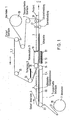
- Fig. 1 in zum Teil vereinfachter Form die.verschiedenen Komponenten der Vakuumverpackungsvorrichtung und deren gegenseitige Anordnung;
- Fig. 2 die Vakuumkammer im Schnitt quer zur Förderrichtung;
- Fig. 3 in Gegenüberstellung eine Vakuumverpackung mit Flächensiegelung und eine Vakuumverpackung mit Flächensiegelung und zusätzlicher Konturensiegelung;
- Fig. 4 die vor der Vakuumkammer angeordnete Vorheizstation für die Oberbahn;
- Fig. 5 oben im Schnitt und unten in Draufsicht das Unterteil der Vakuumkammer einschliesslich Unter- und Oberbahn und dem Packgut;
- Fig. 6 und 7 die Vakuumkammer in geöffnetem Zustand, wobei zwei Beispiele dafür dargestellt sind, wie ein vorzeitiges Aneinanderhaften der Bahnen vermieden werden kann;
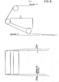
- Fig. 8 oben im Querschnitt und unten in Draufsicht die Führung der Oberfolie unter der Vorheizstation;
- Fig. 9 im Schnitt die Führungskette für die Ober- oder Unterbahn mit geöffneten Klemmgliedern;
- Fig. 10 eine Darstellung ähnlich der von Fig. 9 mit seitlich gekippten, geöffneten Klemmgliedern;
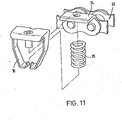
- Fig. 11 in einer Explosionsdarstellung ein Klemmglied der Kette und
- Fig. 12 die Strukturierung des Siegelgummis.
- Fig. 1 in a partially simplified form die.verschie those components of the vacuum packaging device and their mutual arrangement;
- Figure 2 shows the vacuum chamber in cross section to the conveying direction.
- 3 in comparison, a vacuum packaging with surface sealing and a vacuum packaging with surface sealing and additional contour sealing;
- 4 shows the preheating station for the upper web arranged in front of the vacuum chamber;
- Figure 5 above in section and below in plan view the lower part of the vacuum chamber including bottom and top web and the packaged goods.
- 6 and 7 show the vacuum chamber in the open state, two examples being shown of how premature adhesion of the webs can be avoided;
- Fig. 8 above in cross section and below in plan view the guidance of the top film under the preheating station;
- 9 shows in section the guide chain for the upper or lower web with the clamping members open;
- FIG. 10 shows a representation similar to that of FIG. 9 with laterally tilted, open clamping members;
- 11 is an exploded view of a clamping member of the chain and
- 12 the structuring of the sealing rubber.
Durch das Verfahren kann Packgut jeder Art, insbesondere auch verderbliche Lebensmittel, vakuumverpackt werden. Die Verpackung besteht aus einer Oberbahn 1 und einer Unterbahn 2, die zusammengesiegelt sind. Die Bahnen bestehen aus thermoplastischen Kunststofffolien, insbesondere aus Folien thermoplastischer Ionomer-Harze auf der Basis von vernetzten Äthylencopolymeren, wie sie unter der Handelsbezeichnung Surlyn bekannt sind. Die Unterbahn 2 kann jedoch auch aus Karton oder einem anderen starren Material bestehen, das einen Überzug aus einem thermoplastischen Material aufweist und daher mit der Oberbahn 1 heißsiegelbar ist. Die Siegelung der Bahnen besteht aus einer Flächensiegelung und einer zusätzlichen durch Druck und Wärme hergestellten Siegelung in einem schmalen Randstreifen 20, die hier als Konturensiegelung bezeichnet wird.All types of packaged goods, in particular perishable foods, can be vacuum-packed by the method. The packaging consists of an
Bei einer Vakuum-Skin-Packung, die nur eine Flächensiegelung besitzt, besteht die Gefahr, dass durch Falten 21, die sich insbesondere bei Packgut grosser Höhe kaum vermeiden lassen, je nach der Grösse der Falten Luft sofort oder allmählich in die Packung eindringt. Durch den Luftsauerstoff wird dabei die Haltbarkeit von Lebensmitteln verkürzt.In the case of a vacuum skin pack, which has only a surface seal, there is the risk that folds 21, which are particularly difficult to avoid, in particular in the case of packaged goods of great height, will immediately or gradually penetrate air into the pack, depending on the size of the folds. The shelf life of food is shortened by atmospheric oxygen.
Durch die zusätzliche Konturensiegelung werden derartige Falten 21 am Rand der Packung abgedichtet.
Die Vakuum-Skin-Packung wird in der Weise hergestellt, dass das Packgut 5 auf die Unterbahn 2 gelegt wird und über dem Packgut 5 die bereits vorerwärmte Oberbahn 1 angeordnet wird. Zwischen den Bahnen und um das Packgut 5 herum wird die Luft abgezogen und gleichzeitig wird auch die Unterbahn 2 soweit erwärmt, dass sie plastisch ist. Darauf wird durch mechanischen Druck in dem schmalen Randstreifen 20 die Konturensiegelung bewirkt und wird durch Luftdruck auf die Aussenseite der Oberbahn 1 die Oberbahn 1 an das Packgut 5 und gegen die Unterbahn 2 gelegt. Der Randstreifen 20 erstreckt sich um die gesamte Packung herum. Die Packung 3 kann dann von den Bahnen getrennt werden und etwaige Randteile der Bahnen ausserhalb des Randstreifens 20 können abgeschnitten werden.The vacuum skin pack is produced in such a way that the packaged
Die.Temperaturen, auf die die Oberbahn 1 und die Unterbahn 2 erwärmt werden, und der Druck, der auf den Randstreifen 20 ausgeübt wird, hängen von dem Folienmaterial und dessen Stärke ab. Bei Verwendung einer Surlyn-Folie als Material für die Ober- und die Unterbahn wird die Oberbahn auf eine Temperatur von etwa 100°C erwärmt und erfolgt die Erwärmung der Unterbahn durch Kontakt mit einer auf ca. 90°C erwärmten Siegelplatte. Der im Randstreifen 20 ausgeübte Druck liegt in der Grössenordnung von 200 N/cm2. Dieser Druck wird für die Dauer von etwa 1 Sekunde ausgeübt. The temperatures to which the
Zur Durchführung dieses Verfahrens wird die Unterbahn 2 seitlich durch Führungsketten 4 über einen Tisch 22 geführt, auf dem das Packgut 5 von Hand oder mechanisch auf die Unterbahn 2 gelegt wird. Die Führungsketten 4 laufen um Kettenräder 23, 24 am Anfang und am Ende des Tisches 22. Die Unterbahn 2 wird dabei von einer Vorratsrolle 26 abgewickelt und bei dem am Anfang des Tisches 22 angeordneten Kettenrad 23 von Klemmgliedern 27 der Führungskette 4 erfasst. Die Klemmglieder 27 und deren Arbeitsweise werden später noch im einzelnen beschrieben.To carry out this method, the
Die Oberbahn 1 wird durch eine Führungskette 7 mit den gleichen Klemmgliedern 27 wie die Führungskette 4 von einer Vorratsrolle 26 abgewickelt und unter einer Vorheizstation 8 vorbeigeführt, in der die Oberbahn l soweit erwärmt wird, dass sie plastisch ist. Nach der Vorheizstation 8 läuft die Oberbahn 1 in eine Vakuumkammer 9 ein. Die Oberbahn 1 wird auch beim Durchlaufen durch die Vakuumkammer 9 und danach bis zur Ausgabe der Vakuumpackung durch die Führungskette 7 geführt. Die Oberbahn 1 muss daher breiter als die Vakuumkammer 9 sein, da die Führungskette 7 nicht durch die Vakuumkammer 9, sondern seitlich daran vorbeiläuft. Die Unterbahn 2 wird bei dem unmittelbar vor der Vakuumkammer 9 angeordenten Kettenrad 24 freigegeben und die Unterbahn 2 wird hinter dem Kettenrad 24 von der Oberbahn 1, ausgehend von der Stelle, wo beide Bahnen zusammengesiegelt sind, mitgenommen.The
Es besteht auch die Möglichkeit, die Unterbahn 2 nicht durch Führungsketten 4 zu führen, sondern nur ausgehend von der Siegelungsstelle, durch die Oberbahn 1 mitnehmen zu lassen. In der Unterbahn 2 können sich dann jedoch Zugfalten bilden. Ausserdem besitzen die für die Bahn verwendeten thermoplastischen Kunststoffe im warmen Zustand eine sehr kleine mechanische Festigkeit, so dass die Gefahr besteht, dass die Unterbahn 2 reisst oder die Oberbahn 1 entlang ihren beiden Führungsketten 7 abgetrennt wird. Diese Nachteile werden durch die synchron mit der Führungskette 7 laufende Führungskette 4 der Unterbahn 2 vermieden.It is also possible not to guide the
Die Vakuumkammer 9 besteht aus einem anhebbaren und absenkbaren Oberteil 10 und einem stationären Unterteil 11. Das Oberteil 10 ist kastenförmig ausgebildet und ist nach unten offen. Am waagrechten Teil des öffnungsrandes ist ein Siegelgummi 14 angebracht. Das Unterteil 11 besitzt eine Aussparung für eine Siegelplatte 12, die durch hydraulische oder pneumatische Einrichtungen anhebbar und absenkbar ist. Die Siegelplatte 12 wird auf ihrer gesamten Oberseite beheizt, insbesondere auch in den Randbereichen, da die Randbereiche der Unterbahn 2 zur Herstellung der Konturensiegelung eine ausreichend hohe Temperatur besitzen müssen, um das Material plastisch und siegelbar zu machen. Zwischen der Siegelplatte 12 und dem Rand der Aussparung in dem Unterteil 11 ist nur ein geringer Zwischenraum von einigen Millimetern. In der abgesenkten Stellung der Siegelplatte 12 befindet sich deren Oberseite einige Millimeter, vorzugsweise 8 mm, unter dem öffnungsrand des Unterteils 11. In ihrer angehobenen Stellung drückt die Siegelplatte 12 gegen den Siegelgummi 14 und zwischen beiden wird dadurch die Konturensiegelung der beiden Folien hergestellt. Die Breiten- und Längenabmessungen der Siegelplatte 12 müssen daher etwas, nämlich um die Breite des Randstreifens 20 der Konturensiegelung, grösser sein als die lichte Breite und die lichte Länge der offenen Unterseite des Oberteils 10. Unter Breite wird hierbei die Abmessung quer zur Transportrichtung und unter Länge die Abmessung längs der Transportrichtung der beiden Bahnen verstanden. Die Innenabmessungen der Aussparung in dem Unterteil 11 liegen etwa in der Mitte zwischen den Innen- und Aussenabmessungen des öffnungsrandes des Oberteils 10, so dass der äussere Teil des Siegelgummis 14 gegen'deh öffnungsrand der Aussparung des Unterteils 11 anliegt und als Dichtung wirkt. Der Siegelgummi 14 besitzt vorzugsweise eine Strukturierung, wie sie in Fig. 12 gezeigt ist. Durch die Strukturierung wird einerseits erreicht, dass die beiden Bahnen mit hohem Druck zusammengesiegelt werden und wird andererseits vermieden, dass die Oberbahn 1 an dem Siegelgummi 14 festklebt. Die Strukturierung kann zum Beispiel rasterförmig sein, so dass die Oberfläche waffelgemustert ist. Ein geeignetes Material für den Siegelgummi 14 ist Silikonkautschuk mit einer Shorehärte von ca. 70°. Der Siegelgummi 14 kann zum Beispiel dadurch mit dem Oberteil 10 verbunden sein, dass er ein T-förmiges Profil besitzt, das in eine entsprechende Nut des Oberteils 10 eingesetzt wird.The
In der Vakuumkammer 9 wird die Vakuumpackung hergestellt. Das Oberteil 10 wird dabei zunächst soweit angehoben, dass die Unterbahn 2 mit dem darauf angeordneten Packgut 5 und der darüber angeordneten vorerwärmten Oberbahn 1 in die geöffnete Vakuumkammer 9 einlaufen können. Der Transport erfolgt dabei durch die Führungskette 7 der Oberbahn 1. Die Vakuumkammer 9 wird dann geschlossen, das heisst das Oberteil 10 wird auf das Unterteil 11 aufgesetzt, wobei der äussere Teil des Siegelgummis 14 als Dichtung wirkt. Die Oberbahn 1, die breiter als die Vakuumkammer 9 ist, wird zwischen dem Siegelgummi 14 und dem öffnungsrand des Unterteils 11 eingeklemmt. Die Unterbahn 2 ist etwa so breit wie die Siegelplatte 12 und muss auf jeden Fall breiter als die öffnung des Oberteils 10 und schmäler als die Aussparung im Unterteil 11 sein. Die Unterbahn 2 wird dadurch nur am vorderen und hinteren Ende der Vakuumkammer 9 eingeklemmt, jedoch nicht seitlich.The vacuum pack is produced in the
Beim Einlaufen des Packgutes 5 und der Bahnen in die Vakuumkammer und beim Schliessen der Vakuumkammer wird die Oberbahn 1 zeltförmig über das Packgut 5 gespannt.When the packaged
Nach dem Schliessen der Vakuumkammer 9 wird aus dem Unterteil 11 und damit auch um das Packgut 5 herum die Luft abgesaugt, zum Beispiel durch eine an der Unterseite der Aussparung des Unterteils 11 angebrachte Leitung. Während des Absaugens der Luft befindet sich die Siegelplatte 12 noch-in ihrer abgesenkten Stellung, so dass zwischen der Oberbahn 1 und der Unterbahn 2 innerhalb der Vakuumkammer 9 ein Spalt bleibt, durch den die Luft um das Packgut 5 herum abgesaugt werden kann. Der Spalt zwischen der Aussparung im Unterteil 11 und der Siegelplatte 12 ist ebenfalls so bemessen, dass die Luft durch ihn abgesaugt werden kann.After the
Im geschlossenen Zustand der Vakuumkammer 9 ist das Oberteil 10 durch die Oberbahn 1 luftdicht von dem Unterteil 11 abgeschlossen. Um beim Evakuieren des Unterteils 11 einen Druckausgleich zu erhalten, wird daher gleichzeitig auch das Oberteil 10 evakuiert.In the closed state of the
Während des Evakuierens wird die Unterbahn 2 durch Heizeinrichtungen in der Siegelplatte 12 erwärmt und plastisch gemacht.During the evacuation, the
Nach beendeter Evakuierung wird die Siegelplatte 12 durch hydraulische oder pneumatische Einrichtungen, vorzugsweise durch Druckluftkissen 13, nach oben gegen den Siegelgummi 14 gepresst. Dadurch wird die Konturensiegelung zwischen den beiden Bahnen hergestellt und die Packung verschlossen. Während der Siegelzeit wird das Oberteil 10 der Vakuumkammer 9 belüftet, so dass der sich aufbauende atmosphärische Druck die erwärmte, plastische Oberfolie an das Packgut 5 anlegt und so die Packung formt. Durch den noch bestehenden Unterdruck im Unterteil 11 werden beide Bahnen in dem das Packgut 5 umgebenden Teil gemeinsam gegen die Siegelplatte 12 gepresst, wodurch die Flächensiegelung entsteht, bei der beide Bahnen auf der gesamten Fläche rings um das Packgut 5 verschweisst werden.After the evacuation has ended, the sealing
Danach kann die Vakuumkammer 9 geöffnet werden, wozu zweckmäseigerweise zuvor auch das Unterteil 11 belüftet wird. Durch die seitlich noch von ihrer Führungskette festgehaltene Oberbahn 1 kann die fertige Vakuumpackung dann aus der Vakuumkammer 9 herausgezogen werden, wobei gleichzeitig der zur Herstellung der nächsten Vakuumpackung benötigte Teil der Oberbahn 1 und der Unterbahn 2 mit dem darauf angeordneten nächsten packgut 5 in die Vakuumkammer 9 gezogen werden. Beim Austreten aus der Vakuumkammer 9 gelangt die fertige Vakuumpackung 3 zunächst auf eine Kühlplatte 29 und dann in eine Einrichtung 30, in der die Vakuum-. packung 3 in Längs- und Querrichtung von der Oberbahn 1 und der Unterbahn 2 abgeschnitten wird. Bis zu dieser Einrichtung 30 wird die Vakuumpackung von der Führungskette 7 transportiert.Then the
Über dem Unterteil 11 der Vakuumkammer 9 ist zweckmässigerweise noch eine Trenneinrichtung angeordnet, die ein Festkleben der Unterbahn 2 verhindert. Als Trenneinrichtung kann ein hitzebeständiges und reibungsminderndes Band über das Unterteil 11 gespannt sein, das durch Federn 31 auf der einen oder auf beiden Seiten des Unterteils 11 befestigt ist. Das Band ist vorzugsweise ein PTFE-beschichtetes Glasgewebeband 15. Die Spannung in dem Glasgewebeband 15 ist ausreichend, um das Packgut 5 zu halten und zu verhindern, dass die Unterbahn 2 mit dem darauf befindlichen Packgut 5 beim Einlaufen in die geöffnete Vakuumkammer 9, zu welchem Zeitpunkt sich die Siegelplatte 12 noch in ihrem abgesenkten Zustand befindet, unmittelbar auf der Siegelplatte 12 aufliegt. Dadurch soll zum einen eine übermässige Erwärmung des Packgutes 5 vermieden werden und soll zum anderen verhindert werden, dass die Unterbahn 2 und das Packgut 5 beim Einlaufen in die Vakuumkammer 9 über die Stufe nach unten gleiten, die zwischen dem Rand der Aussparung im Unterteil 11 und der im beschriebenen Ausführungsbeispiel etwa 8 mm tiefer liegenden Siegelplatte 12 entsteht, siehe Fig. 5.A separating device, which prevents the
Falls erforderlich, kann auch im Oberteil 10 der Vakuumkammer 9 eine Einrichtung zur weiteren Erwärmung der Oberbahn 1 vorgesehen sein. Wie in Fig. 2 dargestellt, kann die Vakuumkammer 9 durch Trennwände 32 im Oberteil 10 unterteilt werden. An der Unterseite der Trennwand oder der Trennwände 32 ist wieder ein Siegelgummi 14 vorgesehen. In einer einzigen Vakuumkammer 9 können auf diese Weise gleichzeitig mehrere Vakuumpackungen 3 hergestellt werden.If necessary, a device for further heating the
In den Figuren 6 und 7 sind zwei Möglichkeiten dargestellt, wie die Oberbahn 1 geführt werden kann, um zu verhindern, dass sie bereits beim Einlaufen in die geöffnete Vakuumkammer 9 mit der Unterbahn 2 in Berührung kommt und an ihr festklebt. Gemäss Fig. 6 wird ein derartiges Festkleben dadurch verhindert, dass die Führungskette 7 der Oberbahn 1 durch das letzte vor der Vakuumkammer angeordnete Kettenrad 25 in einem spitzen Winkel zu der Unterbahn 2 und zur Ebene der öffnung des Unterteils 11 der Vakuumkammer 9 geführt wird. Der spitze Winkel ist dabei etwa derart, dass die Oberbahn 1 am Einlaufende der Vakuumkammer 9 etwa 6 mm über der Unterbahn 2 einläuft. Dadurch wird sichergestellt, dass die beiden Bahnen nicht vorzeitig-zusammenkleben und dass nach dem Schliessen der Vakuumkammer 9 zwischen beiden Bahnen ein ausreichender Evakuierungsspalt besteht. In Fig. 7 ist eine weitere Möglichkeit dargestellt, um dies zu erreichen. Hierbei ist die Oberbahn 1 im gesamten Bereich der Vakuumkammer 9 etwa um 6 mm angehoben. Diese Anhebung ist in Fig. 7 übertrieben dargestellt. Beim Schliessen der Vakuumkammer 9 wird die Oberbahn 1 dann auf den Rand des Unterteils 11 der Vakuumkammer 9 heruntergedrückt.FIGS. 6 and 7 show two ways in which the
Die Siegelplatte 12 im Unterteil 11 der Vakuumkammer 9 wird elektrisch erwärmt. Durch den Kontakt der Siegelplatte 12 mit den übrigen Teilen der Vakuumkammer und durch Strahlung besteht die Gefahr, dass das Unterteil 11 insgesamt so stark erwärmt wird, dass die Bahnen an ihm festkleben. Um eine. derartige unkontrollierte Erwärmung des Unterteils 11 zu vermeiden, wird vorzugsweise der Öffnungsrand des Unterteils 11 wassergekühlt.The sealing
Durch die Konturensiegelung werden zwar eventuelle Falten 21 in der Oberbahn 1 abgedichtet, dennoch ist es für einen störungsfreien Betrieb der Vorrichtung zweckmässig, Vorkehrungen zu treffen, die bereits das Entstehen derartiger Falten 21 verhindern. Eine der hierzu getroffenen Massnahmen besteht darin, dass, wie bereits erwähnt, auch die Unterbahn 2 bis zur Vakuumkammer 9 durch eine Führungskette 4 transportiert wird. Zur Vermeidung von Falten trägt ferner insbesondere die in den Figuren 9 und 10 dargestellte Ausbildung der Klemmglieder 27 der Führungsketten 4, 7 bei, wie sie in dem DE-GM 7 219 147 im einzelnen beschrieben sind. Die Führungsketten 4, 7 bestehen aus einer Kette 33, z.B. einer Gallschen Kette oder einer Buchsenkette. Die äusseren Kettenlaschen sind als Winkel 34 ausgebildet, die eine Mitnehmerlasche 16 und eine Schraubendruckfeder 35 tragen. Der waagrechte Teil des Winkels 34 bildet zusammen mit der Mitnehmerlasche 16 einens Schnabel, der die Oberbahn 1 bzw, die Unterbahn 2 festhält. Der Hauptteil der Mitnehmerlasche 16 befindet sich über dem Winkel 34 und wird durch die Schraubendruckfeder 35, die sich auf der.gegenüberliegenden, unteren Seite des Winkels 34 befindet, gegen diesen gedrückt.. Durch Druck von unten gegen die Mitnehmerlasche 16 öffnet sich der Schnabel und gibt die Bahn frei. Ein öffnen des Schnabels findet nicht nur beim Ergreifen und Freigeben einer Bahn statt, sondern zweckmässigerweise auch dann, wenn die Führungsketten 4, 7 um Kettenräder 23, 24, 25 umgelenkt werden. Da die Schnäbel gegenüber den Bolzen der Kettenglieder in der Höhe versetzt sind, beschreiben die Schnäbel nämlich beim Umlenken der Ketten einen grösseren Weg als die Kettenglieder selbst, so dass die Bahnen beim Umlenken um Kettenräder ebenfalls einen grösseren Weg beschreiben müssen.und daher gespannt werden. Damit die Spannung in den Bahnen möglichst klein gehalten wird und sich insbesondere nicht an den Schnäbeln konzentriert, werden vorzugsweise die Schnäbel im Bereich der Kettenräder 23, 24, 25 geöffnet. Dies geschieht durch zentrisch oder exzentrisch zu den Kettenrädern 23, 24, 25 angeordnete Ringe oder Scheiben 17. Die exzentrischen Ringe oder Scheiben 17 sind so angeordnet, dass sich die Schnäbel möglichst früh öffnen, damit sich die Spannung und Dehnung der Bahn auf eine möglichst grosse Strecke verteilt.Any folds 21 in the
Eine weitere mit der Führungskette 4. für die Unterbahn 2 verbundene Schwierigkeit besteht darin, dass beim Freigeben der Unterbahn 2 durch das vor der Vakuumkammer 9 angeordnete Kettenrad 24 die Klemmglieder zwar ohne weiteres die Unterbahn in der beschriebenen Weise freigeben können, die geöffneten Klemmglieder dann jedoch um das Kettenrad 24 herum nach unten geführt werden. Dabei besteht die Gefahr, dass die angehobene Mitnehmerlasche 16 den Weg der Unterbahn 2 kreuzt und diese einreisst. Um eine derartige Beschädigung der Unterbahn 2 zu vermeiden, werden die Mitnehmerlaschen im Bereich des Kettenrades 24 nicht nur so wie in der Figur 9 dargestellt angehoben, sondern zugleich zur Seite gekippt, so dass sich der Abstand der Mitnehmerlaschen der zu beiden Seiten der Unterbahn 2 verlaufenden Führungsketten 4 vergrössert und grösser wird als die Breite der Unterbahn 2. Dies geschieht dadurch, dass der exzentrische Ring oder die Scheibe 17 durch einen sich nach aussen konisch verjüngenden Abhebering 18 ersetzt wird. Dadurch dass sich das untere Ende der Mitnehmerlasche 16 an dem Konus des Abhebering 18 anlegt, wird die Mitnehmerlasche 16 nicht nur so wie in Fig. 9 senkrecht angehoben, sondern zugleich seitlich aus dem Weg der Unterbahn 2 weggekippt.Another difficulty associated with the
Bei der Führung der Oberbahn 1 unterhalb der Vorheiz- . station 8 vorbei wird vorzugsweise der Abstand zwischen den Führungsketten 7 verg.rössert, um die Oberbahn 1 möglichst gespannt zu halten und ein Durchhängen der in der Vorheizstation 8 erwärmten Oberbahn 1 zu verhindern. Würde die Oberbahn 1 beim Einlaufen in die Vakuumkammer 9 nämlich durchhängen, so würde dadurch die Faltenbildung beim überspannen desPackgutes.5 begünstigt. Dies ist im einzelnen in Fig. 8 dargestellt. Bei einer zum Beispiel 30 cm breiten Oberbahn 1 ist der Abstand der Kettenräder 25 nach der Vorheizstation 8 um insgesamt etwa 5 mm grösser als der Abstand der Kettenräder 25 vor der Vorheizstation 8, das heisst die Oberbahn 1 wird in der Breite um etwa 5 mm gedehnt. Das Ausmass der Dehnung hängt selbstverständlich von dem Material, der Dicke und der Breite der Oberbahn 1 sowie der Temperatur ab, auf die die Oberbahn 1 durch die Vorheizstation 8 erwärmt wird.When running the
In der Vorheizstation 8 selbst kann die Oberbahn l durch Kontakt mit einer Heizplatte, durch Infrarotstrahler oder durch Heissluft erwärmt werden.In the preheating
Eine Heizplatte hat den Nachteil, dass bei Änderung der zu beheizenden Länge der Oberbahn 1 die Heizplatte entweder ausgewechselt oder teilweise abgedeckt werden muss. Eine unterschiedliche Erwärmung einzelner Zonen ist nur schwer realisierbar ausserdem muss die Oberbahn 1 entweder durch Vakuum oder durch Druckluft in Kontakt mit der Heizplatte gebracht werden, wodurch der mechanische Aufbau vergrössert wird.A heating plate has the disadvantage that when the length of the
Bei Verwendung eines Infrarot-Flächenstrahler ist es ebenfalls schwierig, die beheizte Länge zu ändern oder einzelne Zonen unterschiedlich stark zu erwärmen. Der Einsatz von Heizelementen in Form von rechteckigen Quarzstrahlern oder Quarzröhren führt im allgemeinen ebenfalls zu einer ungleichmässigen Erwärmung der Bahn.When using an infrared panel heater it is also difficult to change the heated length or to heat individual zones to different degrees. The use of heating elements in the form of rectangular quartz lamps or Q uarzröhren also generally results in an uneven heating of the web.
Vorzugsweise wird daher ein Strahlerfeld aus einzelnen Heizelementen 40 zusammengesetzt, wie dies in Fig. 4 dargestellt ist. Die Heizelemente 40 verlaufen quer zur Laufrichtung der Bahn. Um die beheizte Länge der Bahn der jeweiligen Taktlänge der Vorrichtung anpassen zu können, sind mehrere der Heizelemente 40 einzeln abschaltbar. Zur unterschiedlichen Erwärmung einzelner Zonen können Heizelemente 40 unterschiedlicher Leistung eingesetzt werden..Die Leistung der einzelnen Heizelemente 40-kann ferner zum Beispiel durch Triacs gesteuert werden. Das gesamte durch die Heizelemente 40 gebildete Strahlerfeld ist in Längsrichtung gegenüber der Vakuumkammer 9 einstellbar.A radiator array is therefore preferably composed of
Vorzugsweise ist die Vakuumkammer austauschbar ausgebildet, so dass sie mit wenigen Handgriffen durch eine andere Vakuumkammer mit grösseren oder kleineren Abmessungen ersetzt werden kann. Die pro Zyklus zugeführte Länge der Ober- und Unterbahn wird entsprechend der Längsabmessung der Vakuumkammer gesteuert. Die Ausbildung der Heizeinrichtung mit mehreren getrennt steuerbaren Heizelementen 40, die Austauschbarkeit der Vakuumkammer und die Steuerung der Vorschublänge der Ober- und Unterbahn führen zusammen zu einer optimalen Anpassung der jeweiligen Packung an das Packgut.The vacuum chamber is preferably designed to be exchangeable, so that it can be replaced with another vacuum chamber with larger or smaller dimensions in a few simple steps. The length of the top and bottom web fed per cycle is controlled according to the longitudinal dimension of the vacuum chamber. The design of the heating device with several separately
Claims (12)
dass die Oberbahn (1) und die Unterbahn (2) um das Packgut (5) herum in einem Randstreifen (20) zusätzlich durch mechanischen Druck und Wärme zusammengesiegelt werden.1. A method for vacuum packing of packaged goods, wherein the packaged product between a lower web and a O is inserted Berbahn, the air is drawn between the tracks and then the upper web by air pressure against the packaged goods and the lower web is pressed and sealed areally with the lower web is , characterized,
that the upper web (1) and the lower web (2) around the packaged goods (5) in an edge strip (20) are additionally sealed together by mechanical pressure and heat.
dass der öffnungsrand des Oberteils (10) mit einem Siegelgummi (14) versehen ist und eine Einrichtung (Druckluftkissen 13) vorgesehen ist, die die Siegelplatte (12) mit einer ausreichenden Kraft gegen den Siegelgummi (14) drückt, um zwischen der Oberbahn (1) und der Unterbahn (2) eine Verschweissung herzustellen.4. Apparatus for carrying out the method according to one of claims 1 to 3, with a device for feeding the upper web, with a device for feeding the lower web, which is narrower than the upper web, with a heating device for heating the upper web, with a vacuum chamber, which has a top part that is open at the bottom and a bottom part that is open at the top, wherein a sealing plate that is movable against the top part and that is heated at least in the edge region is arranged in a recess in the bottom part, and the opening edge of the top part is one is of such a width that, when the vacuum chamber is closed, it lies against the opening edge of the lower part and that the sealing plate in its raised position overlaps the opening edge of the upper part, the upper web being wider than the vacuum chamber and the lower web wider than the inside dimension of the opening of the upper part , but narrower than the inner dimension of the opening of the lower part, characterized in that
that the opening edge of the upper part (10) is provided with a sealing rubber (14) and a device (compressed air cushion 13) is provided which presses the sealing plate (12) against the sealing rubber (14) with sufficient force to move between the upper web (1 ) and the lower web (2) to produce a weld.
Priority Applications (1)
| Application Number | Priority Date | Filing Date | Title |
|---|---|---|---|
| AT81103098T ATE14555T1 (en) | 1980-04-24 | 1981-04-24 | METHOD AND DEVICE FOR THE MANUFACTURE OF VACUUM SKIN PACKAGING. |
Applications Claiming Priority (2)
| Application Number | Priority Date | Filing Date | Title |
|---|---|---|---|
| DE3015847A DE3015847C2 (en) | 1980-04-24 | 1980-04-24 | Process for vacuum skin packaging of relatively tall packaged goods and device for carrying out the process |
| DE3015847 | 1980-04-24 |
Publications (3)
| Publication Number | Publication Date |
|---|---|
| EP0039056A1 true EP0039056A1 (en) | 1981-11-04 |
| EP0039056B1 EP0039056B1 (en) | 1985-07-31 |
| EP0039056B2 EP0039056B2 (en) | 1991-10-23 |
Family
ID=6100868
Family Applications (1)
| Application Number | Title | Priority Date | Filing Date |
|---|---|---|---|
| EP81103098A Expired - Lifetime EP0039056B2 (en) | 1980-04-24 | 1981-04-24 | Method of and apparatus for producing vacuum skin packages |
Country Status (4)
| Country | Link |
|---|---|
| EP (1) | EP0039056B2 (en) |
| JP (1) | JPS5737508A (en) |
| AT (1) | ATE14555T1 (en) |
| DE (1) | DE3015847C2 (en) |
Cited By (7)
| Publication number | Priority date | Publication date | Assignee | Title |
|---|---|---|---|---|
| EP0126878A1 (en) * | 1983-04-28 | 1984-12-05 | Multivac Sepp Haggenmüller Kg | Web feeding and guiding device for a packaging machine |
| WO1985003487A1 (en) * | 1984-02-08 | 1985-08-15 | Multivac Sepp Haggenmüller Kg | Packaging machine with sealing station |
| US4826065A (en) * | 1983-04-28 | 1989-05-02 | Multivac Sepp Haggenmuller Kg | Feeding means for feeding a machine web in a packaging machine |
| EP0582461A1 (en) * | 1992-08-06 | 1994-02-09 | Idemitsu Petrochemical Co. Ltd. | Method of and apparatus for sealing containers |
| US7478662B2 (en) | 2004-10-09 | 2009-01-20 | Uhlmann Pac-Systeme Gmbh & Co. Kg | Apparatus for sealing foils to each other |
| US9119450B2 (en) | 2012-12-21 | 2015-09-01 | Novartis Ag | Contact lens package |
| WO2020058278A3 (en) * | 2018-09-17 | 2020-05-28 | Gea Food Solutions Germany Gmbh | Packaging machine for producing skin packaging |
Families Citing this family (1)
| Publication number | Priority date | Publication date | Assignee | Title |
|---|---|---|---|---|
| GB2574057A (en) * | 2018-05-25 | 2019-11-27 | Proseal Uk Ltd | Vacuum dome and vacuum skin packaging apparatus |
Citations (8)
| Publication number | Priority date | Publication date | Assignee | Title |
|---|---|---|---|---|
| GB983035A (en) * | 1962-08-02 | 1965-02-10 | Syozo Omori | Method and apparatus for producing vacuum packages for food |
| US3260032A (en) * | 1963-06-07 | 1966-07-12 | William M Hill | Apparatus for making packages |
| US3634993A (en) * | 1970-05-06 | 1972-01-18 | Young William E | Bottom platen apparatus for forming skin packaging |
| DE2161465A1 (en) * | 1971-12-10 | 1973-06-14 | American Can Co | PROCESS AND EQUIPMENT FOR MANUFACTURING HERMETICALLY SEALED PACKAGES FROM WHICH THE AIR HAS BEEN REMOVED |
| DE2449452A1 (en) * | 1973-10-17 | 1975-04-30 | Du Pont | PROCESS FOR MANUFACTURING SKIN PACKS |
| DE2608777A1 (en) * | 1976-03-03 | 1977-09-08 | Multivac Hagenmueller Kg | Package sealing station for automatic package wrapping machine - has serrated surface on sealing bar to reduce possibility of it sticking to film web |
| DE2808836A1 (en) * | 1977-03-01 | 1978-09-07 | Omori Machinery | VACUUM PACKING PROCESS AND VACUUM PACKAGING DEVICE |
| DE2843166A1 (en) * | 1978-10-04 | 1980-04-24 | Dixie Union Verpackungen Gmbh | Vacuum packing machine for goods - has chambers of profiled material with front and rear walls on lid |
Family Cites Families (10)
| Publication number | Priority date | Publication date | Assignee | Title |
|---|---|---|---|---|
| DE7219147U (en) * | 1974-07-25 | Multivac Haggenmueller S Kg | Retaining clip for strips of packaging material on packaging machines | |
| US2017459A (en) * | 1932-07-16 | 1935-10-15 | Hallett D Howe | Stencil printing and flocking machine |
| US2106612A (en) * | 1935-08-06 | 1938-01-25 | Gen Electric | Straightener for woven material |
| GB840949A (en) * | 1957-03-28 | 1960-07-13 | Cellophane Invest Company Ltd | Method and apparatus for packaging |
| BE631180A (en) * | 1962-04-17 | |||
| US3491504A (en) * | 1967-10-02 | 1970-01-27 | William E Young | Method and apparatus for vacuum skin packaging |
| US3686822A (en) * | 1970-09-14 | 1972-08-29 | Young William E | Apparatus and method for skin packaging |
| DE7340032U (en) * | 1973-11-08 | 1977-09-15 | Hermann Waldner Gmbh & Co, 7988 Wangen | Material web conveyor |
| DE2364565C2 (en) * | 1973-12-24 | 1983-01-05 | Multivac Sepp Haggenmüller KG, 8941 Wolfertschwenden | Method and vacuum packaging device for producing a package |
| CA1086206A (en) * | 1976-11-30 | 1980-09-23 | Timothy T. Day | Process and apparatus for vacuum packing |
-
1980
- 1980-04-24 DE DE3015847A patent/DE3015847C2/en not_active Expired
-
1981
- 1981-04-22 JP JP6112481A patent/JPS5737508A/en active Pending
- 1981-04-24 AT AT81103098T patent/ATE14555T1/en not_active IP Right Cessation
- 1981-04-24 EP EP81103098A patent/EP0039056B2/en not_active Expired - Lifetime
Patent Citations (8)
| Publication number | Priority date | Publication date | Assignee | Title |
|---|---|---|---|---|
| GB983035A (en) * | 1962-08-02 | 1965-02-10 | Syozo Omori | Method and apparatus for producing vacuum packages for food |
| US3260032A (en) * | 1963-06-07 | 1966-07-12 | William M Hill | Apparatus for making packages |
| US3634993A (en) * | 1970-05-06 | 1972-01-18 | Young William E | Bottom platen apparatus for forming skin packaging |
| DE2161465A1 (en) * | 1971-12-10 | 1973-06-14 | American Can Co | PROCESS AND EQUIPMENT FOR MANUFACTURING HERMETICALLY SEALED PACKAGES FROM WHICH THE AIR HAS BEEN REMOVED |
| DE2449452A1 (en) * | 1973-10-17 | 1975-04-30 | Du Pont | PROCESS FOR MANUFACTURING SKIN PACKS |
| DE2608777A1 (en) * | 1976-03-03 | 1977-09-08 | Multivac Hagenmueller Kg | Package sealing station for automatic package wrapping machine - has serrated surface on sealing bar to reduce possibility of it sticking to film web |
| DE2808836A1 (en) * | 1977-03-01 | 1978-09-07 | Omori Machinery | VACUUM PACKING PROCESS AND VACUUM PACKAGING DEVICE |
| DE2843166A1 (en) * | 1978-10-04 | 1980-04-24 | Dixie Union Verpackungen Gmbh | Vacuum packing machine for goods - has chambers of profiled material with front and rear walls on lid |
Cited By (7)
| Publication number | Priority date | Publication date | Assignee | Title |
|---|---|---|---|---|
| EP0126878A1 (en) * | 1983-04-28 | 1984-12-05 | Multivac Sepp Haggenmüller Kg | Web feeding and guiding device for a packaging machine |
| US4826065A (en) * | 1983-04-28 | 1989-05-02 | Multivac Sepp Haggenmuller Kg | Feeding means for feeding a machine web in a packaging machine |
| WO1985003487A1 (en) * | 1984-02-08 | 1985-08-15 | Multivac Sepp Haggenmüller Kg | Packaging machine with sealing station |
| EP0582461A1 (en) * | 1992-08-06 | 1994-02-09 | Idemitsu Petrochemical Co. Ltd. | Method of and apparatus for sealing containers |
| US7478662B2 (en) | 2004-10-09 | 2009-01-20 | Uhlmann Pac-Systeme Gmbh & Co. Kg | Apparatus for sealing foils to each other |
| US9119450B2 (en) | 2012-12-21 | 2015-09-01 | Novartis Ag | Contact lens package |
| WO2020058278A3 (en) * | 2018-09-17 | 2020-05-28 | Gea Food Solutions Germany Gmbh | Packaging machine for producing skin packaging |
Also Published As
| Publication number | Publication date |
|---|---|
| EP0039056B2 (en) | 1991-10-23 |
| DE3015847A1 (en) | 1981-10-29 |
| ATE14555T1 (en) | 1985-08-15 |
| EP0039056B1 (en) | 1985-07-31 |
| DE3015847C2 (en) | 1985-11-07 |
| JPS5737508A (en) | 1982-03-01 |
Similar Documents
| Publication | Publication Date | Title |
|---|---|---|
| DE2327286C2 (en) | Packaging device | |
| DE69724015T2 (en) | Device and method for producing sealed packaging | |
| DE3316065C2 (en) | Process for filling, venting and sealing bags | |
| EP0379927A2 (en) | Reclosable package and method and device for its manufacture | |
| CH464775A (en) | Method for packaging goods, in particular edible goods, including protective gas and means for carrying out the method | |
| DE3140336C2 (en) | Pack for flowable filling goods and device for producing the pack | |
| DE19504157A1 (en) | bag | |
| DE2122110A1 (en) | Method and arrangement for producing skin packaging | |
| DE2808836C2 (en) | Device for automatic vacuum packaging | |
| EP0039056B1 (en) | Method of and apparatus for producing vacuum skin packages | |
| CH437108A (en) | Apparatus for welding a ribbon to a series of openings in a moving web of material | |
| DE2419682A1 (en) | PACKAGING DEVICE AND PACKAGING METHOD | |
| DE2460974A1 (en) | PROCESS AND DEVICE FOR PACKAGING ARTICLES WITH A STRETCHABLE FILM | |
| CH417449A (en) | Device for packing bulk goods in a protective gas atmosphere | |
| WO1985003487A1 (en) | Packaging machine with sealing station | |
| CH687813A5 (en) | A device for sealing the film webs made of thermoplastic material. | |
| EP0343266A1 (en) | Method for manufacturing containers from a web and apparatus for carrying out this method | |
| DE3151463C2 (en) | ||
| EP0506645B1 (en) | Apparatus for fabrication of battery plate envelopes | |
| EP0928270B1 (en) | Device for vacuumizing and closing bags | |
| EP0750547B1 (en) | Process and device for producing a flowable product package via a shell | |
| DE2751100A1 (en) | PROCESS AND DEVICE FOR PACKAGING UNDER VACUUM | |
| DE102006059770B3 (en) | Packaging method for cutting off projecting ends on foil bags by a torch with pieces of packaging of different sizes envelopes the pieces of packaging in foil material by welding them in | |
| DE2834076C2 (en) | ||
| DE1486029C (en) | Method and apparatus for the manufacture of packs |
Legal Events
| Date | Code | Title | Description |
|---|---|---|---|
| PUAI | Public reference made under article 153(3) epc to a published international application that has entered the european phase |
Free format text: ORIGINAL CODE: 0009012 |
|
| AK | Designated contracting states |
Designated state(s): AT BE CH FR GB IT LU NL SE |
|
| 17P | Request for examination filed |
Effective date: 19820504 |
|
| ITF | It: translation for a ep patent filed |
Owner name: BARZANO' E ZANARDO MILANO S.P.A. |
|
| GRAA | (expected) grant |
Free format text: ORIGINAL CODE: 0009210 |
|
| AK | Designated contracting states |
Designated state(s): AT BE CH FR GB IT LI LU NL SE |
|
| REF | Corresponds to: |
Ref document number: 14555 Country of ref document: AT Date of ref document: 19850815 Kind code of ref document: T |
|
| ET | Fr: translation filed | ||
| PLBI | Opposition filed |
Free format text: ORIGINAL CODE: 0009260 |
|
| 26 | Opposition filed |
Opponent name: MULTIVAC SEPP HAGGENMUELLER KG Effective date: 19860429 |
|
| NLR1 | Nl: opposition has been filed with the epo |
Opponent name: MULTIVAC SEPP HAGGENMUELLER KG |
|
| ITTA | It: last paid annual fee | ||
| PUAH | Patent maintained in amended form |
Free format text: ORIGINAL CODE: 0009272 |
|
| STAA | Information on the status of an ep patent application or granted ep patent |
Free format text: STATUS: PATENT MAINTAINED AS AMENDED |
|
| 27A | Patent maintained in amended form |
Effective date: 19911023 |
|
| AK | Designated contracting states |
Kind code of ref document: B2 Designated state(s): AT BE CH FR GB IT LI LU NL SE |
|
| ITF | It: translation for a ep patent filed |
Owner name: BARZANO' E ZANARDO MILANO S.P.A. |
|
| REG | Reference to a national code |
Ref country code: CH Ref legal event code: AEN |
|
| NLR2 | Nl: decision of opposition | ||
| ET3 | Fr: translation filed ** decision concerning opposition | ||
| NLR3 | Nl: receipt of modified translations in the netherlands language after an opposition procedure | ||
| EPTA | Lu: last paid annual fee | ||
| EAL | Se: european patent in force in sweden |
Ref document number: 81103098.0 |
|
| PGFP | Annual fee paid to national office [announced via postgrant information from national office to epo] |
Ref country code: LU Payment date: 19971223 Year of fee payment: 18 |
|
| PGFP | Annual fee paid to national office [announced via postgrant information from national office to epo] |
Ref country code: CH Payment date: 19980401 Year of fee payment: 18 |
|
| PGFP | Annual fee paid to national office [announced via postgrant information from national office to epo] |
Ref country code: FR Payment date: 19980408 Year of fee payment: 18 |
|
| PGFP | Annual fee paid to national office [announced via postgrant information from national office to epo] |
Ref country code: AT Payment date: 19980410 Year of fee payment: 18 |
|
| PGFP | Annual fee paid to national office [announced via postgrant information from national office to epo] |
Ref country code: GB Payment date: 19980415 Year of fee payment: 18 |
|
| PGFP | Annual fee paid to national office [announced via postgrant information from national office to epo] |
Ref country code: SE Payment date: 19980423 Year of fee payment: 18 |
|
| PGFP | Annual fee paid to national office [announced via postgrant information from national office to epo] |
Ref country code: NL Payment date: 19980430 Year of fee payment: 18 |
|
| PGFP | Annual fee paid to national office [announced via postgrant information from national office to epo] |
Ref country code: BE Payment date: 19980512 Year of fee payment: 18 |
|
| PG25 | Lapsed in a contracting state [announced via postgrant information from national office to epo] |
Ref country code: LU Free format text: LAPSE BECAUSE OF EXPIRATION OF PROTECTION Effective date: 19990424 Ref country code: GB Free format text: LAPSE BECAUSE OF NON-PAYMENT OF DUE FEES Effective date: 19990424 Ref country code: AT Free format text: LAPSE BECAUSE OF NON-PAYMENT OF DUE FEES Effective date: 19990424 |
|
| PG25 | Lapsed in a contracting state [announced via postgrant information from national office to epo] |
Ref country code: SE Free format text: LAPSE BECAUSE OF NON-PAYMENT OF DUE FEES Effective date: 19990425 |
|
| PG25 | Lapsed in a contracting state [announced via postgrant information from national office to epo] |
Ref country code: LI Free format text: LAPSE BECAUSE OF NON-PAYMENT OF DUE FEES Effective date: 19990430 Ref country code: CH Free format text: LAPSE BECAUSE OF NON-PAYMENT OF DUE FEES Effective date: 19990430 Ref country code: BE Free format text: LAPSE BECAUSE OF NON-PAYMENT OF DUE FEES Effective date: 19990430 |
|
| BERE | Be: lapsed |
Owner name: DIXIE-UNION VERPACKUNGEN G.M.B.H. Effective date: 19990430 |
|
| PG25 | Lapsed in a contracting state [announced via postgrant information from national office to epo] |
Ref country code: NL Free format text: LAPSE BECAUSE OF NON-PAYMENT OF DUE FEES Effective date: 19991101 |
|
| GBPC | Gb: european patent ceased through non-payment of renewal fee |
Effective date: 19990424 |
|
| REG | Reference to a national code |
Ref country code: CH Ref legal event code: PL |
|
| PG25 | Lapsed in a contracting state [announced via postgrant information from national office to epo] |
Ref country code: FR Free format text: LAPSE BECAUSE OF NON-PAYMENT OF DUE FEES Effective date: 19991231 |
|
| NLV4 | Nl: lapsed or anulled due to non-payment of the annual fee |
Effective date: 19991101 |
|
| EUG | Se: european patent has lapsed |
Ref document number: 81103098.0 |
|
| REG | Reference to a national code |
Ref country code: FR Ref legal event code: ST |
|
| APAH | Appeal reference modified |
Free format text: ORIGINAL CODE: EPIDOSCREFNO |