EP0037332B1 - Beidseitige Klebevorrichtung für eine Wellpappenmaschine - Google Patents
Beidseitige Klebevorrichtung für eine Wellpappenmaschine Download PDFInfo
- Publication number
- EP0037332B1 EP0037332B1 EP19810400486 EP81400486A EP0037332B1 EP 0037332 B1 EP0037332 B1 EP 0037332B1 EP 19810400486 EP19810400486 EP 19810400486 EP 81400486 A EP81400486 A EP 81400486A EP 0037332 B1 EP0037332 B1 EP 0037332B1
- Authority
- EP
- European Patent Office
- Prior art keywords
- roller
- cylinder
- web
- cardboard
- gluing
- Prior art date
- Legal status (The legal status is an assumption and is not a legal conclusion. Google has not performed a legal analysis and makes no representation as to the accuracy of the status listed.)
- Expired
Links
Images

Classifications
-
- B—PERFORMING OPERATIONS; TRANSPORTING
- B31—MAKING ARTICLES OF PAPER, CARDBOARD OR MATERIAL WORKED IN A MANNER ANALOGOUS TO PAPER; WORKING PAPER, CARDBOARD OR MATERIAL WORKED IN A MANNER ANALOGOUS TO PAPER
- B31F—MECHANICAL WORKING OR DEFORMATION OF PAPER, CARDBOARD OR MATERIAL WORKED IN A MANNER ANALOGOUS TO PAPER
- B31F1/00—Mechanical deformation without removing material, e.g. in combination with laminating
- B31F1/20—Corrugating; Corrugating combined with laminating to other layers
- B31F1/24—Making webs in which the channel of each corrugation is transverse to the web feed
- B31F1/26—Making webs in which the channel of each corrugation is transverse to the web feed by interengaging toothed cylinders cylinder constructions
- B31F1/28—Making webs in which the channel of each corrugation is transverse to the web feed by interengaging toothed cylinders cylinder constructions combined with uniting the corrugated webs to flat webs ; Making double-faced corrugated cardboard
- B31F1/2818—Glue application specially adapted therefor
Definitions
- the present invention relates to machines intended for making, by gluing from one or more strips of single-sided corrugated cardboard and a strip of cover paper, a strip of double-sided, double-double corrugated cardboard, etc.
- gluer In which on the one hand the strip of cover paper is preheated, and on the other hand glue is deposited on the top of the grooves of the single-sided cardboard strip, after having also preheated the latter.
- glue is deposited on the top of the grooves of the single-sided cardboard strip, after having also preheated the latter.
- This splicer is followed by a second machine, called a “double-sided” in which the two strips are applied one on the other and glued by heating the glue previously deposited on the crests of the single-sided cardboard.
- a gluing machine of the same type is then used, provided with two, three, etc. post for gluing the crests of each of the single-sided cardboard strips used. All these strips as well as the strip of cover paper are then applied one on the other and glued by heating in the double-sided.
- the gluers currently known use a coating device such as for example described and represented in FIG. 1 of French patent n ° 1,455,170.
- a coating device such as for example described and represented in FIG. 1 of French patent n ° 1,455,170.
- the liquid glue contained in a container is deposited on the top of the grooves by friction of these on an applicator roller which partially dips in the container and rotates continuously.
- the preheated strip of single-sided cardboard is kept in contact with the applicator roller by means of a pressure roller mounted on two articulated levers and held in position by two cylinders for adjusting the position of this pressure roller as a function of the height of the grooves. .
- the devices currently known do not make it possible to cut the sheet at the time of the end of an order and to keep it on standby for automatic and immediate restarting at the time of a new manufacture. of the same type. With these known devices, it is necessary to carry out the initial installation of the layers, or "boarding", entirely by hand, which in particular introduces a detrimental loss of time.
- the splicer of the invention does not have the drawbacks of the devices known hitherto. It is characterized in that its coating device (s) are each provided with a pressure roller equipped with means for retaining the single-sided carbon strip thereon.
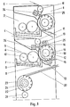
- the splicer 1 shown diagrammatically in FIG. 1 is a splicer with two gluing stations (2, 3) of the ridges of the single (4) or double (4, 5) strip of single-sided cardboard, and is therefore capable of operating either for making double-sided cardboard, or for making double-double cardboard.
- each of the gluing stations (2, 3) comprises an applicator roller, or glue roller 6 dipping in glue 7 contained in a container 8.
- the container 8 has a double bottom defining a space 9 in which water is circulated so as to prevent the temperature of the adhesive from rising too high.
- the thickness of glue conveyed by the gluing roller 6 is a function of the adjustable difference between this gluing roller and a laminating roller 10, sometimes also called doctor's roller. Also extremely conventionally and not shown, the cylinders 6 and 10 are rotated from a double-sided cylinder by means of a universal joint shaft, an auxiliary motor driving them also at low speed during machine stops to avoid drying of the glue.
- the sheet 4 of single-sided cardboard passes around a deflection roller 11, free to rotate, then passes around a disengageable pressing roller 12 which applies it, in a manner known per se, against the gluing roller 6, and is finally directed towards the double-sided.
- the. pressure roller 12 is adjustable in position using an eccentric 13 allowing the end levers 14 which support it to be moved rigidly, this mode of support and position adjustment being identical to that ordinarily used for the cylinder laminator 10.
- the pressing cylinder 12 is a suction cylinder, so that when the adhesive takes up through the top of its grooves, the sheet of single-sided cardboard 4 is held firmly against the roller 12 against which it remains applied over a non-negligible portion of circumference as can be seen in the drawing.
- the cylinder 12 has a hollow interior space 15 in which staurant vapor is circulated so as to preheat the sheet 4.
- longitudinal channels 16 regularly distributed.
- Axial holes 17 of a smaller diameter are also drilled regularly along each channel 16 and put each of them in communication with larger cavities 18 machined on the outside of the cylinder 12.
- Each sector 19 is connected to a vacuum pump, not shown, and operating continuously.
- each channel 16 passes alternately through the sectors 19 and then into the open air.
- the passage in front of the sectors 19 makes it possible to transmit the depression due to the vacuum pump on the cavities 18 which correspond to the channels 16 located in said sectors.
- the cardboard is consequently held by suction against the pressing cylinder 12 throughout the retaining zone encompassed by the sectors 19. The cardboard is then released by bringing the channels 16 back into the open air when these escape the sectors 19.
- the disengageable roller 12 is rotated from the double face and therefore operates in synchronism with the rest of the machine.
- the machine shown comprises, in addition to a second gluing station 2 identical to the station 3 which has just been described, a circuit for feeding and preheating the sheet of cover paper 20 comprising, in addition to a deflection roller 21, a preheater roller 22 known per se but which has the particularity, in accordance with the invention, of being a suction roller identical to the roller 12 previously described, the suction retention being defined by the sectors 23 identical to the sectors 19.
- a circuit for feeding and preheating the sheet of cover paper 20 comprising, in addition to a deflection roller 21, a preheater roller 22 known per se but which has the particularity, in accordance with the invention, of being a suction roller identical to the roller 12 previously described, the suction retention being defined by the sectors 23 identical to the sectors 19.
- roller 22 mounted on a free wheel in a conventional manner for all the driven rollers equipping this type of machine, is provided at the end of the shaft with an auxiliary motor 24 shown diagrammatically by dotted lines which, after stopping the machine and with the help of suction, makes it easier to load the sheet of cover paper in the double-sided.
- the disengageable roller 12 is disengaged and it is released from the gluing roller 6 by maneuvering the eccentric 13.
- the single-sided cardboard then remains immobile and pressed against the roller 12 by suction, which prevents it from touching the glue roller 6 which, as mentioned above, continues to rotate at low speed during machine stops. It is therefore possible to keep awaiting boarding the start of a single-sided cardboard sheet, while it is very difficult to do it on current splicers, since nothing retains the "soft" of the sheet between the preheater cylinder and the gluing station. We can thus prepare an embarkation or leave, after the end of an order for a certain type of groove, the sheet of this type of groove engaged in the gluer. To do this, it is necessary to cut the single-sided ply when the manufacturing is finished.
- the jack 26 When the operator initiates the cut, the jack 26 is stressed and the blade 25 crosses the width of the machine by cutting the sheet of single-sided cardboard. As the paper advances during cutting, a bias cut is made, the cardboard tip already cut continuing to advance until the cut is finished. When the torque is finished, the cylinder 12 is disengaged, which therefore stops turning. The ply engaged in the gluing machine remains held by suction on the roller 12. The deflection roller 11 allows the cardboard to always have the same circuit up to the roller 12, so that the blade 25 always meets the ply of the same way.
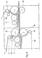
- the gluing stations (2, 3), identical to those previously described, instead of being located one above the other, are located one behind the other.
- the cover preheater 22 is then against the pressing cylinder 12 of the first upstream gluing station 3 as shown in the figure, so as to place the single-sided sheet 4 on the cover paper 20, thus making it possible to pre-stick these two sheets one on top of the other just after the groove has received the glue.
- the double-sided cardboard leaves the gluer by being pre-glued, unlike the current arrangement where the two sheets only stick in the double-sided.
- a calibration carried out in a conventional manner of the center distance of the rollers 12 and 23 makes it possible to take account of the groove height. It is the same on the second bonding station 2 where a calibration of the center distance between its pressure roller 12 and an additional support roller 27 not driven allows to take into account the sum of the heights of the grooves.
Landscapes
- Engineering & Computer Science (AREA)
- Mechanical Engineering (AREA)
- Machines For Manufacturing Corrugated Board In Mechanical Paper-Making Processes (AREA)
Claims (9)
Applications Claiming Priority (2)
| Application Number | Priority Date | Filing Date | Title |
|---|---|---|---|
| FR8007188A FR2479032A1 (fr) | 1980-03-31 | 1980-03-31 | Colleuse double-face pour machine de fabrication de carton ondule |
| FR8007188 | 1980-03-31 |
Publications (2)
| Publication Number | Publication Date |
|---|---|
| EP0037332A1 EP0037332A1 (de) | 1981-10-07 |
| EP0037332B1 true EP0037332B1 (de) | 1983-06-29 |
Family
ID=9240324
Family Applications (1)
| Application Number | Title | Priority Date | Filing Date |
|---|---|---|---|
| EP19810400486 Expired EP0037332B1 (de) | 1980-03-31 | 1981-03-27 | Beidseitige Klebevorrichtung für eine Wellpappenmaschine |
Country Status (4)
| Country | Link |
|---|---|
| EP (1) | EP0037332B1 (de) |
| JP (1) | JPS56137953A (de) |
| DE (1) | DE3160518D1 (de) |
| FR (1) | FR2479032A1 (de) |
Cited By (2)
| Publication number | Priority date | Publication date | Assignee | Title |
|---|---|---|---|---|
| DE19506778A1 (de) * | 1995-02-27 | 1996-08-29 | Bhs Corr Masch & Anlagenbau | Verfahren zum Herstellen von Wellpappe |
| US8672825B2 (en) | 2008-03-21 | 2014-03-18 | Hbk Family, Llc | Apparatus for producing corrugated board |
Families Citing this family (10)
| Publication number | Priority date | Publication date | Assignee | Title |
|---|---|---|---|---|
| JPS58220726A (ja) * | 1982-06-17 | 1983-12-22 | 株式会社磯輪鉄工所 | 段ボ−ルシ−ト製造機における糊付け装置 |
| DE19506777A1 (de) * | 1995-02-27 | 1996-08-29 | Bhs Corr Masch & Anlagenbau | Verfahren zum Herstellen von Wellpappe und Einrichtung hierfür |
| US6068701A (en) * | 1998-02-23 | 2000-05-30 | Kohler Coating Machinery Corporation | Method and apparatus for producing corrugated cardboard |
| US6602546B1 (en) | 2002-06-21 | 2003-08-05 | Coater Services, Inc. | Method for producing corrugated cardboard |
| US7267153B2 (en) | 2004-03-02 | 2007-09-11 | Herbert B Kohler | Corrugator glue machine having web tension nulling mechanism |
| US8057621B2 (en) | 2005-04-12 | 2011-11-15 | Kohler Herbert B | Apparatus and method for producing a corrugated product under ambient temperature conditions |
| US7595086B2 (en) | 2005-10-27 | 2009-09-29 | Kohler Herbert B | Method for producing corrugated cardboard |
| EP2391505B1 (de) | 2009-01-22 | 2021-03-10 | Intpro, Llc | Verfahren zur feuchtigkeits- und temperaturregelung bei einem wellvorgang |
| BR112015009902B8 (pt) | 2012-11-01 | 2023-04-25 | Hbk Family Llc | Dispositivos de formação para formar uma trama longitudinalmente corrugada |
| MX2022001055A (es) | 2019-08-05 | 2022-02-21 | Intpro Llc | Metodo de control de humedad especifica para papel en una banda de papel itinerante. |
Family Cites Families (1)
| Publication number | Priority date | Publication date | Assignee | Title |
|---|---|---|---|---|
| FR1494318A (fr) * | 1966-07-29 | 1967-09-08 | Creusot Forges Ateliers | Procédé et machine pour la fabrication continue de carton ondulé rigide, à ondulations croisées |
-
1980
- 1980-03-31 FR FR8007188A patent/FR2479032A1/fr active Granted
-
1981
- 1981-03-02 JP JP2978081A patent/JPS56137953A/ja active Pending
- 1981-03-27 DE DE8181400486T patent/DE3160518D1/de not_active Expired
- 1981-03-27 EP EP19810400486 patent/EP0037332B1/de not_active Expired
Cited By (2)
| Publication number | Priority date | Publication date | Assignee | Title |
|---|---|---|---|---|
| DE19506778A1 (de) * | 1995-02-27 | 1996-08-29 | Bhs Corr Masch & Anlagenbau | Verfahren zum Herstellen von Wellpappe |
| US8672825B2 (en) | 2008-03-21 | 2014-03-18 | Hbk Family, Llc | Apparatus for producing corrugated board |
Also Published As
| Publication number | Publication date |
|---|---|
| FR2479032B1 (de) | 1982-02-19 |
| EP0037332A1 (de) | 1981-10-07 |
| JPS56137953A (en) | 1981-10-28 |
| FR2479032A1 (fr) | 1981-10-02 |
| DE3160518D1 (en) | 1983-08-04 |
Similar Documents
| Publication | Publication Date | Title |
|---|---|---|
| EP0037332B1 (de) | Beidseitige Klebevorrichtung für eine Wellpappenmaschine | |
| EP0131475B1 (de) | Verfahren und Vorrichtung zum Umhüllen eines Faserballens mit einer Schutzhülle | |
| EP0662045B2 (de) | Vorrichtung und verfahren zur herstellung einseitiger wellpappe | |
| EP0758295B1 (de) | Vorrichtung und verfahren zur herstellung einer einseitig beklebten wellpappe durch angetriebenes leimungsverfahren | |
| EP0038237B1 (de) | Einseitige Wellpappenmaschine | |
| EP2145755B1 (de) | Verfahren zur Formung von Winkelprofilen und Vorrichtung zur Umsetzung dieses Verfahrens | |
| EP0117782B1 (de) | Vorrichtung zur augenblicklichen Einstellung einer Leimauftragsbreite während der Fertigung von Wellpapier und Verfahren zum Verwerten derselben | |
| EP0921938B1 (de) | Maschine und vorrichtung zum herstellen von einseitiger wellpappe unter verwendung von reibförderung | |
| EP0560692B1 (de) | Einrichtung zum Kontaktbeheizen von Bahnen | |
| JPH1034776A (ja) | シングルフェーサの糊付装置 | |
| EP0297501B1 (de) | Frankiermaschine mit einer Wahlweise arbeitenden Ausgabe für entweder trockene oder aufgefeuchtete, bedruckte Etiketten | |
| EP0699610A1 (de) | Vorrichtung zum Schneiden und klebstofflosen Anbringen des Bahnanfangs für eine neue Wickelrolle auf den Wickelkern eines Wicklers | |
| EP0153220A2 (de) | Maschine zum Warmkleben von Geweben oder Filmen auf eine biegsame oder harte Tragbahre | |
| FR2647053A1 (fr) | Mecanisme d'entrainement pour carton ondule simple face dans une machine a onduler | |
| FR2465027A1 (fr) | Perfectionnement aux machines de fabrication de carton ondule | |
| FR2744994A1 (fr) | Procede d'enroulement d'une bande de materiau sur un noyau, moyens en vue de la mise en oeuvre du procede d'enroulement et enroulements ainsi obtenus | |
| BE1012168A7 (fr) | Procede de fabrication de serviettes et machine pour sa mise en oeuvre. | |
| CA3081906A1 (fr) | Appareil et procede de pose de bandelette sur une bande de roulement | |
| EP0072315A1 (de) | Verfahren und Maschine zur Herstellung eines Rohrförmigen Zylinders aus Karton, insbesondere eines Fasskörpers, und Kartonzylinder durch dieses Verfahren hergestellt | |
| FR2549811A1 (fr) | Montage de rouleaux a rotation, pour machines a imprimer | |
| FR2679541A1 (fr) | Dispositif de coupe et de collage bout a bout pour machine a derouler. | |
| FR2737679A1 (fr) | Dispositif de formation de carton ondule simple face | |
| BE348883A (de) | ||
| CH259455A (fr) | Installation servant à appliquer un enduit sur une bande. | |
| BE562022A (de) |
Legal Events
| Date | Code | Title | Description |
|---|---|---|---|
| PUAI | Public reference made under article 153(3) epc to a published international application that has entered the european phase |
Free format text: ORIGINAL CODE: 0009012 |
|
| AK | Designated contracting states |
Designated state(s): DE GB IT |
|
| 17P | Request for examination filed |
Effective date: 19810804 |
|
| ITF | It: translation for a ep patent filed |
Owner name: JACOBACCI & PERANI S.P.A. |
|
| GRAA | (expected) grant |
Free format text: ORIGINAL CODE: 0009210 |
|
| AK | Designated contracting states |
Designated state(s): DE GB IT |
|
| REF | Corresponds to: |
Ref document number: 3160518 Country of ref document: DE Date of ref document: 19830804 |
|
| PLBE | No opposition filed within time limit |
Free format text: ORIGINAL CODE: 0009261 |
|
| STAA | Information on the status of an ep patent application or granted ep patent |
Free format text: STATUS: NO OPPOSITION FILED WITHIN TIME LIMIT |
|
| 26N | No opposition filed | ||
| ITTA | It: last paid annual fee | ||
| PGFP | Annual fee paid to national office [announced via postgrant information from national office to epo] |
Ref country code: GB Payment date: 19980318 Year of fee payment: 18 |
|
| PGFP | Annual fee paid to national office [announced via postgrant information from national office to epo] |
Ref country code: DE Payment date: 19980403 Year of fee payment: 18 |
|
| PG25 | Lapsed in a contracting state [announced via postgrant information from national office to epo] |
Ref country code: GB Free format text: LAPSE BECAUSE OF NON-PAYMENT OF DUE FEES Effective date: 19990327 |
|
| GBPC | Gb: european patent ceased through non-payment of renewal fee |
Effective date: 19990327 |
|
| PG25 | Lapsed in a contracting state [announced via postgrant information from national office to epo] |
Ref country code: DE Free format text: LAPSE BECAUSE OF NON-PAYMENT OF DUE FEES Effective date: 20000201 |