EP0035452B1 - Cellule de réfrigération ou de congélation rapide en continu - Google Patents
Cellule de réfrigération ou de congélation rapide en continu Download PDFInfo
- Publication number
- EP0035452B1 EP0035452B1 EP19810400310 EP81400310A EP0035452B1 EP 0035452 B1 EP0035452 B1 EP 0035452B1 EP 19810400310 EP19810400310 EP 19810400310 EP 81400310 A EP81400310 A EP 81400310A EP 0035452 B1 EP0035452 B1 EP 0035452B1
- Authority
- EP
- European Patent Office
- Prior art keywords
- refrigerating
- freezing cell
- chamber
- support means
- cell
- Prior art date
- Legal status (The legal status is an assumption and is not a legal conclusion. Google has not performed a legal analysis and makes no representation as to the accuracy of the status listed.)
- Expired
Links
- 238000007710 freezing Methods 0.000 title claims description 18
- 230000008014 freezing Effects 0.000 title claims description 18
- 238000011282 treatment Methods 0.000 claims description 17
- 239000007788 liquid Substances 0.000 claims description 7
- 238000000638 solvent extraction Methods 0.000 claims description 6
- XLYOFNOQVPJJNP-UHFFFAOYSA-N water Substances O XLYOFNOQVPJJNP-UHFFFAOYSA-N 0.000 claims description 3
- 239000012267 brine Substances 0.000 claims description 2
- HPALAKNZSZLMCH-UHFFFAOYSA-M sodium;chloride;hydrate Chemical compound O.[Na+].[Cl-] HPALAKNZSZLMCH-UHFFFAOYSA-M 0.000 claims description 2
- 238000009434 installation Methods 0.000 description 13
- 238000005057 refrigeration Methods 0.000 description 11
- 238000004519 manufacturing process Methods 0.000 description 5
- 239000003507 refrigerant Substances 0.000 description 5
- 239000003795 chemical substances by application Substances 0.000 description 4
- 238000001816 cooling Methods 0.000 description 4
- 230000033001 locomotion Effects 0.000 description 3
- FAPWRFPIFSIZLT-UHFFFAOYSA-M Sodium chloride Chemical compound [Na+].[Cl-] FAPWRFPIFSIZLT-UHFFFAOYSA-M 0.000 description 2
- 230000001105 regulatory effect Effects 0.000 description 2
- 230000005540 biological transmission Effects 0.000 description 1
- 230000001143 conditioned effect Effects 0.000 description 1
- 238000000034 method Methods 0.000 description 1
- 238000012986 modification Methods 0.000 description 1
- 230000004048 modification Effects 0.000 description 1
- 230000000630 rising effect Effects 0.000 description 1
- 238000005096 rolling process Methods 0.000 description 1
- 239000011780 sodium chloride Substances 0.000 description 1
- 238000005507 spraying Methods 0.000 description 1
- 230000003068 static effect Effects 0.000 description 1
- 230000001360 synchronised effect Effects 0.000 description 1
Images
Classifications
-
- F—MECHANICAL ENGINEERING; LIGHTING; HEATING; WEAPONS; BLASTING
- F25—REFRIGERATION OR COOLING; COMBINED HEATING AND REFRIGERATION SYSTEMS; HEAT PUMP SYSTEMS; MANUFACTURE OR STORAGE OF ICE; LIQUEFACTION SOLIDIFICATION OF GASES
- F25D—REFRIGERATORS; COLD ROOMS; ICE-BOXES; COOLING OR FREEZING APPARATUS NOT OTHERWISE PROVIDED FOR
- F25D13/00—Stationary devices, e.g. cold-rooms
- F25D13/06—Stationary devices, e.g. cold-rooms with conveyors carrying articles to be cooled through the cooling space
- F25D13/065—Articles being submerged in liquid coolant
Definitions
- the present invention relates to a continuous rapid cooling or freezing cell.
- the aim of the present invention is to avoid these drawbacks, and makes it possible to produce an economical, autonomous cell, easily movable, ensuring continuous refrigeration or freezing, products and easily adjustable or adaptable to fill a large number of operating variants both in terms of cold production and mechanical means of transport and handling of products subject to treatment.
- Another characteristic of the invention is that the cell makes it possible, for a given degree of cold, supplied by own means of producing cold, to regulate the speed of treatment of the products and thus to obtain either freezing or refrigeration.
- a continuous refrigeration or freezing cell for processing products packaged in sealed or non-sealed trays comprising a thermally insulated enclosure divided into at least two parts and clean and autonomous means for producing cold
- the enclosure comprises means for supporting these products, forming an endless system with a single vertical loop, adjustable in position relative to its upper wall and thermally insulating partitioning means, retractable in the passage areas of these support means and dividing its interior space into two vertically superimposed parts.
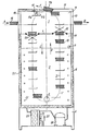
- the refrigeration cell shown comprises clean, autonomous means for producing cold 6 and an insulated refrigeration enclosure 8, divided internally into two parts by thermally insulating partitioning means.
- the first part of this enclosure, or part 1 of the inlet comprises access means allowing the introduction of the products to be cooled and the outlet thereof from this enclosure after treatment.
- the second part of this enclosure, or part 2 of the treatment provides a refrigeration treatment proper. These parts are vertically superimposed.
- a suitably conditioned product is deposited in the inlet part 1, on support means 3, driven by drive or motor means 4.
- the product passes from part 1 to part 2 through partitioning means 5 partly retractable, preferably retractable only in the areas of passage of the product subjected to the treatment.
- the support means 3 in the form, for example, of an endless system, comprises a chain 7 in a simple, vertical, closed loop which carries trays or grids 17 constantly maintained horizontally by known techniques.
- the chain 7 is set in motion by drive or motor means 4 to produce a continuous movement of the products subjected to the treatment; following arrows C and D.
- the cell has a front face and a rear face.
- the front face has an opening 18 allowing the introduction of the packaged product into a tray 19 for example.
- the arrow A indicates the direction of introduction of the tray 19.
- the following introduction movement A is synchronized with a passage at this level of a grid or plate 17, the support means 3 moving in continuous scrolling according to the arrows C and D.
- the opening 18 can be closed by a curtain, not shown, which retracts when a tray 19 is introduced.
- the inlet part 1 of the enclosure also has on its rear face outlet means 14 comprising an opening 13. This latter opening can also be closed by a curtain which retracts when leaving a tray 19 following arrow B.
- the entry part 1 also includes in its upper part a opening 15 whose edge located on the side of the front face has an inclined slope in the form of a bevel 16.
- Part 2 of the enclosure includes cooling means.
- These cooling means comprise an evaporator 22 in the form of a heat exchange coil 27, this evaporator forming part of the cold production means 6 for bringing the products packaged in trays 19 to the desired degree of cold, during the treatment time allowed.
- the heat exchange agent 27 is a liquid chosen from water, sodium chloride brine, etc. This liquid is brought through a float valve-circulation circuit 9 assembly, in part 2, to a predetermined level. Zone 11, located between this level of liquid and the partitioning means 5, constitutes a drainage zone and the tray 19 containing the product is sealed.
- the cell When the heat exchange liquid is water, the cell is limited in its treatment to a use of refrigeration.
- the heat exchange agent When the heat exchange agent is a gas or air, it is either pulsed by one or more fans not shown or projected by one or more known spraying devices not shown.
- the own independent means of producing the cold 6 mainly comprise a motor-compressor 26, a condenser 23, a fan 24 and its motor 25.
- the cooling means arranged in the processing part 2 include the evaporator 22, supplied with refrigerant by the circuit of these cold production means 6, and the heat exchange agent 27.
- This evaporator 22 is an evaporator of the fin coil type or with thermal transmission plates.
- the cell according to the invention can be mechanical or entirely manual loading and unloading.
- the support means 3 comprise grids or plates 17 with or without retaining edge 17b and constantly maintained in their horizontal position by means of known type. These support means 3 are vertically adjustable and placed at a predetermined distance below the upper wall of the enclosure 8 to allow unloading either by the outlet along E, that is to say the opening 15 or by the opening 13, i.e. through opening 18.
- the loading can be done by a not shown loader which places the trays 19 on the grids or trays 17, through the opening 18.
- the unloading can be done by a unloader which grabs the treated trays 19 and takes them out by the opening 13.
- loading and unloading are carried out manually, through the single opening 18, the grid or tray 17 discharged being immediately recharged by a new tray 19 to be cooled.
- a single opening 18 is open during loading-unloading.
- the other two openings 15 and 13 are closed by doors or shutters not shown.
- the loading by the opening 18 and the unloading by outlet E are fully automatic.
- Loading means cause trays 19 to be treated in the inlet part 1 through the opening 18 according to arrow A, in synchronism with passages of the grids 17.
- the grids 17, mounted as previously on the support means 3, comprise, a bottom 17a and at least one edge 17b placed opposite the side of introduction of the tray 19 pushed by the loading means according to arrow A.
- This edge 17b allows on the one hand to limit the stroke of the tray 19 introduced along A and on the other hand, the grid 17 having completed its complete course in the enclosure 8, to remove the tray 19 from the enclosure 8 by pushing it from behind according to arrow E on the beveled edge 16 of the opening 15.
- the support means 3 must in this example be mounted near the upper wall of the enclosure 8 so that each grid or plate 17 passes just under the bevel 16 of the opening 15, and that the bevelled edge 16 can be introduced under the tray 19 to take it out and push it into means of transport such as a treadmill not shown, mounted outside the enclosure 8, which moves it away from the cell.
- the two openings 15 and 18 are open at least during loading or unloading.
- the opening 13 is closed by a shutter or door not shown.
- the openings 15 and 18, in order to limit the loss of cold, may include flexible closing flaps or retractable doors when the trays 19 pass.
- the grid or tray 17 may or may not have an edge 17b. If the grid 17 has an edge 17b, the unloading means comprise gripping members for lifting the tray 19 and moving it away from the cell. If the grid 17 does not have an edge 17b, the unloading means can, for example comprise a conveyor belt and a lever, or arm which pushes the tray 19 along arrow B, the conveyor belt moving the tray 19 away from the cell.
- the partitioning means 5 comprise retractable doors when the grids 17 pass: the door 20 retractable in the direction of the arrow C and the door 12 retractable in the direction of the arrow D.
- These doors can be constituted by flexible or flexible or sliding shutters which return to their closed position, once the grid 17 has passed.
- the cell according to the invention can comprise a cold enclosure 8 having more than two parts 1 and 2.
- successive parts or compartments of cold can be operative to carry out a sequence of successive refrigerating treatments in cascade each having its own characteristics. They may or may not be separated by parts of compartments such as the inlet part 1 which allow access to the trays 19 during refrigeration treatment, for example to add a product being cooled.
- the user of the cabinet has several possibilities for adjusting the treatment.
- the first possibility consists in playing on the means for producing the cold 6 in a known manner, for example with an adjustable regulating thermostat placed on the electric circuit of the motor-compressor 26.
- Another possibility consists in adjusting the treatment speed by supplying more or less the motor means 4 of the support means 3.
- the refrigeration treatment time is regulated and, on the other hand, the rate of entry of the treated product.
- a combination of these two adjustment possibilities makes it possible, depending on the heat exchange agent 27 chosen, to obtain freezing or refrigeration of the trays 19 introduced at will.
- the support means 3 are placed in a position clearly below the upper wall of the enclosure 8.
Landscapes
- Engineering & Computer Science (AREA)
- Chemical & Material Sciences (AREA)
- Combustion & Propulsion (AREA)
- Physics & Mathematics (AREA)
- Mechanical Engineering (AREA)
- Thermal Sciences (AREA)
- General Engineering & Computer Science (AREA)
- Devices That Are Associated With Refrigeration Equipment (AREA)
Applications Claiming Priority (2)
| Application Number | Priority Date | Filing Date | Title |
|---|---|---|---|
| FR8004604A FR2477273A1 (fr) | 1980-02-29 | 1980-02-29 | Cellule de regrigeration ou de congelation rapide en continu |
| FR8004604 | 1980-02-29 |
Publications (3)
| Publication Number | Publication Date |
|---|---|
| EP0035452A2 EP0035452A2 (fr) | 1981-09-09 |
| EP0035452A3 EP0035452A3 (en) | 1982-10-13 |
| EP0035452B1 true EP0035452B1 (fr) | 1984-06-06 |
Family
ID=9239189
Family Applications (1)
| Application Number | Title | Priority Date | Filing Date |
|---|---|---|---|
| EP19810400310 Expired EP0035452B1 (fr) | 1980-02-29 | 1981-02-27 | Cellule de réfrigération ou de congélation rapide en continu |
Country Status (3)
| Country | Link |
|---|---|
| EP (1) | EP0035452B1 (enExample) |
| DE (1) | DE3163936D1 (enExample) |
| FR (1) | FR2477273A1 (enExample) |
Families Citing this family (4)
| Publication number | Priority date | Publication date | Assignee | Title |
|---|---|---|---|---|
| EP1972874B1 (de) * | 2007-03-20 | 2019-02-13 | Liconic Ag | Automatisiertes Substanzenlager |
| PL2208951T3 (pl) | 2009-01-19 | 2018-10-31 | Liconic Ag | Zautomatyzowana przechowalnia niskotemperaturowa do próbek laboratoryjnych ze zautomatyzowanym dostępem |
| PL2470458T3 (pl) * | 2009-08-28 | 2015-05-29 | Klaus Peter Bak | Urządzenie do regulowania temperatury przechowywania artykułów spożywczych i sposób jego działania |
| EP2743614B1 (de) | 2012-12-12 | 2019-10-02 | Liconic Ag | Lagerkassette für Laborobjekte |
Family Cites Families (12)
| Publication number | Priority date | Publication date | Assignee | Title |
|---|---|---|---|---|
| US1898758A (en) * | 1930-09-11 | 1933-02-21 | Vogt Instant Freezers Inc | Refrigerating apparatus for packaged goods |
| US2196643A (en) * | 1937-01-15 | 1940-04-09 | Reeh Johannes | Plant for freezing and storing fish on ships |
| DE678784C (de) * | 1937-02-18 | 1939-07-21 | Fritz Wilhelm Fechner | Vorrichtung zum Gefrieren von Lebensmitteln |
| FR897969A (fr) * | 1942-07-17 | 1945-04-06 | Teves Gmbh Alfred | Réfrigérateur à chapelets pour produits devant être intensément refroidis |
| US3022636A (en) * | 1960-02-29 | 1962-02-27 | Liquefreeze Company Inc | Method and apparatus for freezing cooked foods |
| US3114248A (en) * | 1961-10-20 | 1963-12-17 | Willard L Morrison | Method and apparatus for freezing hot cooked food |
| US3228206A (en) * | 1964-02-24 | 1966-01-11 | Lockerby W Lee | Food freezing apparatus |
| US3300993A (en) * | 1964-02-25 | 1967-01-31 | Alfred H Schlemmer | Freezing apparatus and method |
| DE1451088A1 (de) * | 1964-08-14 | 1969-07-10 | Hoppe & Krooss Gmbh Maschinenf | Kontinuierlich arbeitende Tiefgefriereinrichtung fuer in Schalen gefuelltes Fischgut |
| NL6714252A (enExample) * | 1967-10-20 | 1969-04-22 | ||
| US3580000A (en) * | 1969-03-17 | 1971-05-25 | Integral Process Syst Inc | Chamber for food treating apparatus |
| GB1287325A (en) * | 1970-06-03 | 1972-08-31 | British Oxygen Co Ltd | Apparatus for cooling a series of workpieces |
-
1980
- 1980-02-29 FR FR8004604A patent/FR2477273A1/fr active Granted
-
1981
- 1981-02-27 EP EP19810400310 patent/EP0035452B1/fr not_active Expired
- 1981-02-27 DE DE8181400310T patent/DE3163936D1/de not_active Expired
Also Published As
| Publication number | Publication date |
|---|---|
| DE3163936D1 (en) | 1984-07-12 |
| FR2477273B1 (enExample) | 1984-05-18 |
| FR2477273A1 (fr) | 1981-09-04 |
| EP0035452A2 (fr) | 1981-09-09 |
| EP0035452A3 (en) | 1982-10-13 |
Similar Documents
| Publication | Publication Date | Title |
|---|---|---|
| US5715685A (en) | Method and apparatus for transporting/storing chilled goods | |
| EP0069688B1 (fr) | Procédé de surgélation et de conditionnement de produits individuels, et dispositif pour la mise en oeuvre de ce procédé | |
| EP0337860B1 (fr) | Conteneur isotherme à réservoir de produit réfrigérant et application au transport de produits frais | |
| US2926507A (en) | Refrigerating apparatus | |
| US2254420A (en) | Refrigerating apparatus | |
| EP0591047B1 (fr) | Conteneur isotherme, notamment pour le transport de produits frais ou surgelés | |
| JPS6015111Y2 (ja) | 冷却物品陳列用冷却または冷凍容器 | |
| EP0035452B1 (fr) | Cellule de réfrigération ou de congélation rapide en continu | |
| FR2539221A1 (fr) | Appareil de traitement continu de produits par un fluide de refroidissement | |
| EP0968395B1 (fr) | Chariot refrigere | |
| FR2682848A1 (fr) | Procede et dispositif d'application de micro-ondes a des produits a des fins notamment de decongelation, rechauffage, sechage. | |
| FR2476288A1 (fr) | Appareil pour porter des objets ou des articles a basse temperature | |
| FR2489492A1 (fr) | Procede et appareil de stockage de substances biologiques congelees | |
| EP0546968A1 (fr) | Dispositif de distribution de plateaux-repas avec réfrigération et système d'introduction ou d'évacuation des plateaux et système de fermeture du module technique | |
| FR2679988A1 (fr) | Procede pour limiter le givrage de la batterie frigorifique d'un meuble frigorifique ouvert et meuble mettant en óoeuvre ce procede. | |
| FR2639424A1 (fr) | Meubles de conservation de produits par le froid | |
| EP0176462B1 (fr) | Procédé de cuisson de produits alimentaires tels que des jambons et installation le mettant en oeuvre | |
| EP0918473B1 (fr) | Enceinte de surgelation en continu a tables refrigerees superposees | |
| EP0578523A1 (fr) | Installation de cuisson et de refroidissement en continu de produits alimentaires préconditionnés | |
| FR2779810A1 (fr) | Procede de refroidissement d'enceintes refrigerees et enceintes appliquant ce procede | |
| BE465927A (enExample) | ||
| WO2001081843A1 (fr) | Dispositif pour optimiser la surgelation en continu de produits en vrac, individuellement, une installation equipee dudit dispositif et application dudit dispositif | |
| WO2013034826A1 (fr) | Systeme d'amelioration de l'equilibrage des gaz froids dans un tunnel de surgelation par la mise en œuvre de zones tampon et de volets interieurs | |
| FR2773393A1 (fr) | Tunnel de surgelation de produits alimentaires a film d'entrainement interrompu | |
| FR2793005A1 (fr) | Procede et appareil de refroidissement en continu d'un produit au moyen d'un fluide cryogenique |
Legal Events
| Date | Code | Title | Description |
|---|---|---|---|
| PUAI | Public reference made under article 153(3) epc to a published international application that has entered the european phase |
Free format text: ORIGINAL CODE: 0009012 |
|
| AK | Designated contracting states |
Designated state(s): DE FR GB |
|
| PUAL | Search report despatched |
Free format text: ORIGINAL CODE: 0009013 |
|
| AK | Designated contracting states |
Designated state(s): DE FR GB |
|
| 17P | Request for examination filed |
Effective date: 19830307 |
|
| RBV | Designated contracting states (corrected) |
Designated state(s): DE FR GB |
|
| GRAA | (expected) grant |
Free format text: ORIGINAL CODE: 0009210 |
|
| AK | Designated contracting states |
Designated state(s): DE FR GB |
|
| REF | Corresponds to: |
Ref document number: 3163936 Country of ref document: DE Date of ref document: 19840712 |
|
| PGFP | Annual fee paid to national office [announced via postgrant information from national office to epo] |
Ref country code: DE Payment date: 19850122 Year of fee payment: 5 |
|
| PLBE | No opposition filed within time limit |
Free format text: ORIGINAL CODE: 0009261 |
|
| STAA | Information on the status of an ep patent application or granted ep patent |
Free format text: STATUS: NO OPPOSITION FILED WITHIN TIME LIMIT |
|
| 26N | No opposition filed | ||
| PG25 | Lapsed in a contracting state [announced via postgrant information from national office to epo] |
Ref country code: FR Free format text: LAPSE BECAUSE OF NON-PAYMENT OF DUE FEES Effective date: 19881028 |
|
| PG25 | Lapsed in a contracting state [announced via postgrant information from national office to epo] |
Ref country code: DE Effective date: 19881101 |
|
| GBPC | Gb: european patent ceased through non-payment of renewal fee | ||
| PG25 | Lapsed in a contracting state [announced via postgrant information from national office to epo] |
Ref country code: GB Free format text: LAPSE BECAUSE OF NON-PAYMENT OF DUE FEES Effective date: 19881118 |
|
| REG | Reference to a national code |
Ref country code: FR Ref legal event code: ST |