EP0034539A2 - Anlage zur Rückgewinnung von Bestandteilen einer Mischung ungleicher Komponenten, wie z.B. Fertigbeton - Google Patents
Anlage zur Rückgewinnung von Bestandteilen einer Mischung ungleicher Komponenten, wie z.B. Fertigbeton Download PDFInfo
- Publication number
- EP0034539A2 EP0034539A2 EP81400233A EP81400233A EP0034539A2 EP 0034539 A2 EP0034539 A2 EP 0034539A2 EP 81400233 A EP81400233 A EP 81400233A EP 81400233 A EP81400233 A EP 81400233A EP 0034539 A2 EP0034539 A2 EP 0034539A2
- Authority
- EP
- European Patent Office
- Prior art keywords
- installation
- rotor
- distributor
- mixture
- hopper
- Prior art date
- Legal status (The legal status is an assumption and is not a legal conclusion. Google has not performed a legal analysis and makes no representation as to the accuracy of the status listed.)
- Ceased
Links
Images

Classifications
-
- B—PERFORMING OPERATIONS; TRANSPORTING
- B03—SEPARATION OF SOLID MATERIALS USING LIQUIDS OR USING PNEUMATIC TABLES OR JIGS; MAGNETIC OR ELECTROSTATIC SEPARATION OF SOLID MATERIALS FROM SOLID MATERIALS OR FLUIDS; SEPARATION BY HIGH-VOLTAGE ELECTRIC FIELDS
- B03B—SEPARATING SOLID MATERIALS USING LIQUIDS OR USING PNEUMATIC TABLES OR JIGS
- B03B9/00—General arrangement of separating plant, e.g. flow sheets
- B03B9/06—General arrangement of separating plant, e.g. flow sheets specially adapted for refuse
- B03B9/061—General arrangement of separating plant, e.g. flow sheets specially adapted for refuse the refuse being industrial
- B03B9/063—General arrangement of separating plant, e.g. flow sheets specially adapted for refuse the refuse being industrial the refuse being concrete slurry
-
- B—PERFORMING OPERATIONS; TRANSPORTING
- B03—SEPARATION OF SOLID MATERIALS USING LIQUIDS OR USING PNEUMATIC TABLES OR JIGS; MAGNETIC OR ELECTROSTATIC SEPARATION OF SOLID MATERIALS FROM SOLID MATERIALS OR FLUIDS; SEPARATION BY HIGH-VOLTAGE ELECTRIC FIELDS
- B03B—SEPARATING SOLID MATERIALS USING LIQUIDS OR USING PNEUMATIC TABLES OR JIGS
- B03B11/00—Feed or discharge devices integral with washing or wet-separating equipment
-
- B—PERFORMING OPERATIONS; TRANSPORTING
- B65—CONVEYING; PACKING; STORING; HANDLING THIN OR FILAMENTARY MATERIAL
- B65G—TRANSPORT OR STORAGE DEVICES, e.g. CONVEYORS FOR LOADING OR TIPPING, SHOP CONVEYOR SYSTEMS OR PNEUMATIC TUBE CONVEYORS
- B65G53/00—Conveying materials in bulk through troughs, pipes or tubes by floating the materials or by flow of gas, liquid or foam
- B65G53/34—Details
- B65G53/40—Feeding or discharging devices
- B65G53/46—Gates or sluices, e.g. rotary wheels
- B65G53/4608—Turnable elements, e.g. rotary wheels with pockets or passages for material
- B65G53/4625—Turnable elements, e.g. rotary wheels with pockets or passages for material with axis of turning perpendicular to flow
- B65G53/4633—Turnable elements, e.g. rotary wheels with pockets or passages for material with axis of turning perpendicular to flow the element having pockets, rotated from charging position to discharging position, i.e. discrete flow
- B65G53/4641—Turnable elements, e.g. rotary wheels with pockets or passages for material with axis of turning perpendicular to flow the element having pockets, rotated from charging position to discharging position, i.e. discrete flow with means for clearing out the pockets
-
- Y—GENERAL TAGGING OF NEW TECHNOLOGICAL DEVELOPMENTS; GENERAL TAGGING OF CROSS-SECTIONAL TECHNOLOGIES SPANNING OVER SEVERAL SECTIONS OF THE IPC; TECHNICAL SUBJECTS COVERED BY FORMER USPC CROSS-REFERENCE ART COLLECTIONS [XRACs] AND DIGESTS
- Y02—TECHNOLOGIES OR APPLICATIONS FOR MITIGATION OR ADAPTATION AGAINST CLIMATE CHANGE
- Y02W—CLIMATE CHANGE MITIGATION TECHNOLOGIES RELATED TO WASTEWATER TREATMENT OR WASTE MANAGEMENT
- Y02W30/00—Technologies for solid waste management
- Y02W30/50—Reuse, recycling or recovery technologies
- Y02W30/58—Construction or demolition [C&D] waste
Definitions
- the present invention relates to an installation for the recovery of the elements of a mixture with a heterogeneous and sticky consistency, formed of variable proportions of coarse solid material, of fine solid material and of liquid, the flow rate of reception of the mixture being itself variable, and in particular to a recovery facility for ready-mixed concrete waste.
- ready to use in which the concrete is prepared in advance in a plant where the mixture of aggregates, sand, cement is prepared. and water in suitable proportions and from where this mixture is sent to the points of use using trucks generally carrying a rotating concrete mixer.
- the waste produced is simply discharged into a pit or a dirt pit, but such ways of operating are less and less tolerated by regulations, and the operator of the power station is more and more often brought do not discharge any water, i.e. operate in a closed circuit, and recover separately aggregates, sand and cement to reintroduce them, in carefully dosed and limited quantities, into the mixture which is intended for the user and to recycle the washing water.
- the aim of the present invention is to provide a solution to these problems, and in particular to provide an installation which allows the recovery of ready-mixed concrete waste under the most satisfactory conditions from the point of view of pollution risks, and this for a cost price and an investment as reduced as possible.
- the present invention therefore provides an installation for the recovery of the elements of a mixture with a heterogeneous and sticky consistency, formed of variable proportions of coarse solid material, of fine solid material and of liquid, the flow rate of reception of the mixture being itself variable.
- installation which comprises at least two receiving hoppers, means for separating by screening, cycloning, spinning and decanting the various mixing elements, the receiving hoppers each being equipped with a distributor whose normal flow is less than the normal flow of the installation for recovering the elements of the mixture, and is less than the instantaneous flow rate which is liable to be poured into the corresponding hopper, this installation having the particularity that it includes means for detecting whether a hopper is empty or if it is full, and authorize the operation of one or more of the distributors, in case the corresponding hopper is full, and this dan s limit the normal flow rate of the recovery installation, and prohibit the operation of other distributors that would cause this same flow rate to be exceeded.
- the installation if it is intended for receive the material to be treated by trucks, it includes a truck presence detector above each hopper, these detectors emitting a signal which authorizes the starting of the corresponding distributor in the same way as the signals emitted by the means which detect whether the hopper is empty or full, effective start-up of the corresponding distributor is nevertheless prohibited if one or more other distributors supply a flow rate equal to the normal flow rate of the installation.
- an evacuation corridor Preferably, under the distributor rotor is disposed an evacuation corridor, with a slight slope in which the mixture delivered by the rotor falls on a continuous sheet of water of small thickness.
- the installation advantageously includes means for decanting and regenerating the water, and in this case it can be provided that this water is reused for washing the vehicles bringing the mixture to be treated, and / or its possible dilution before sending to the hoppers, the formation in the hoppers of tangential currents opposing the vaulting, or for the entrainment of the mixture leaving the distributor.
- the installation includes a buffer capacity between the distributors and the installation which separates the components of the mixture, and that said buffer capacity consists of a pit which operates at constant level thanks to the recycling of a portion water, controlled by a level sensor.
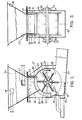
- the installation as a whole comprises a reception area 1 designed for two concrete mixer trucks which come for the cleaning and / or unloading of excess concrete.
- the concrete added with a variable quantity of washing water coming from the lances directed towards the interior and the spout of the concrete mixer, falls into two receiving hoppers 2a and 2b at the base of each of which are placed two alveolar distributors 3a , 3b, which flow into a pit 4, where the material is taken up by a pump 5 to be sent to a treatment installation 6, which separates the aggregates, the cement mud and the clear water.
- This installation which includes screens, cyclones, spin dryers, decanters, is of a conventional type and is therefore not described here in detail.
- the washing water from the outside of the trucks and from the washing area itself is collected by the latter to also feed into the pit 4.
- the clear water recovered in the treatment plant is recycled to be used for truck washing and it is also used in the operation of the dispenser, as will be explained further.
- the signals from these various sensors are connected to an automatic control unit 10, itself connected to light indicators 11a, 11b.
- the light signal 11a allows the concrete to be emptied into one or other of the hoppers 2a, 2b, the treatment installation 6 being in good working order.
- a time delay stops the operation of the treatment unit if one or more trucks have been placed in the emptying position without having loaded any of the hoppers 2a, 2b.
- the detector 9 triggers the starting of the treatment unit 6 and pump 5.
- each hopper 2a or 2b The capacity of each hopper 2a or 2b is approximately 8m 3 , and the flow rate of each distributor 3a, -3b is approximately 12m 3 / h of concrete and that of the pump approximately 92m 3 / h of mixed water and concrete.
- the difference of 80 m 3 / h between these two flows, comes from the fact that the transfer of the concrete from the pit 4 to the treatment station 6 takes place hydraulically, which requires a relatively large amount of water compared to the concrete. , this water coming on the one hand from the various injections made.
- the truck can indifferently pour its load into the hopper 2a in operation, provided that it still has sufficient reception capacity, or in the hopper 2b waiting.
- FIGS 2 and 3 relate to the distribution. alveolar tor 3a, it being understood that the distributor 3b is identical.
- This consists of a housing 32; a rotor 25 and an ejection passage 42.
- the casing 32 fixed to the base of the hopper 2a carries at its upper part a flow funnel 20 which ensures the continuity of the hopper inside the distributor.
- This funnel of quadrangular shape, has 3 vertical sides 21, 22, 23, the latter being opposite an inclined side 24, the slope of which is steep enough for the concrete to slide over it without difficulty.
- the housing 32 also carries the bearings 33 and 3 4 which support the shaft 35 of the distributor rotor 3a.
- the horizontal rotor 25 comprises a shaft 35 to which are attached six radial partitions 27 connected to each other by two circular flanges 28 and 29 whose radius is greater than that of these partitions.
- the distance between the parallel sides 21 and 22 of the funnel is slightly smaller or identical to that which separates the two flanges 28 and 29.
- the sides 21, 22 end downwards by an edge in the form of an arc of a circle concentric with the rotor and which arrives near the flanges 28, 29.
- a lateral seal is provided between the sides 21, 22 and the flanges 28, 29 by two rubber plates 30, 31 tightened on the sides 21, 22 by means of metal plates 36, 37.
- the rubber plates 30; 31 rub against the internal surface of the flanges 28, 29 and the effort of applying them, and thereby the sealing effect, is accentuated by the thrust of the mixture located in the hopper.
- the rubber plates 30, 31 descend lower than the sides 21, 22 and arrive near the rotor.
- the direction of rotation of the rotor is such that the outer edge of the partitions 27, in the upper part of its travel, passes first near the inclined side 24, then on a vertical side 23.
- the third vertical side 23 of the funnel is also doubled and extended on its internal face by a rubber plate 38, which descends to the vicinity of the volume swept by the partitions 27 in their rotation.
- the inclined side 24 of the funnel descends to the immediate vicinity of the same cylindrical volume swept by the partitions, and is connected to a piece of cylindrical sheet 39, coaxial with the rotor.
- the partitions 27 of the rotor carry a rubber plate 40 which protrudes slightly towards the outside, and rubs slightly on the sheet 39 during the rotation of the rotor.
- the rubber plate 40 is held against the partition 27 by means of a plywood 26.
- This plywood is folded parallel to the axis of the rotor, so as to avoid jamming of the materials in the narrow part of the cells in the vicinity of the axis, the position of this fold further making it possible to adjust the capacity of each cell.
- the third vertical side 23 of the funnel is connected to a piece of cylindrical sheet 41 coaxial with the rotor and ending in lower part by a flat vertical surface from the level of the horizontal axis of the rotor shaft to the ejection corridor.
- the radius of the cylindrical part of the sheet 41 is slightly less than the radius of the flanges 28, 29, and the space between the end of the rubber plates 40 of the rotor and this sheet 41 allows a flow avoiding the jamming of the materials and practically canceling the friction of the materials on this sector, since the materials are then no longer under pressure in the cells of the rotor.
- an ejection passage 42 which extends in a direction perpendicular to the axis of the rotor, with a downward slope of the order of 8%, its total length being of the order of 2 times the diameter of the rotor.
- This corridor is integral with the casing 32, its bottom is flat, and its vertical walls are more spaced apart than the flanges 28, 29.
- a water chamber 43 which communicates with the corridor by an orifice 44 in the form slot located flush with the bottom of this corridor, and providing a flat jet injector, capable of producing a sheet of water of small thickness which covers the bottom of the corridor continuously.
- the orifice 44 is formed from a folded sheet, of the same width as the corridor, and is adjustable in height to adjust the thickness of the water table.
- a water injector 45 directed towards the rotor 25 and intended to ensure its complete cleaning.
- peripheral injectors 46, 47 horizontal, placed tangentially to the wall of the hopper and which create, at two levels, streams of water which follow the wall and oppose bonding and vaulting.
- an arc AB of 62 to 66 ° is suitable.
- the distance BC between the lower edges of the side 24 and of the rubber plate 38 is also to be considered.
- this distance which corresponds to the opening of the funnel, is too small, there will be risks of blockage or bending, but, if it is too large and exceeds the vertical of the plane too much the axis of the rotor, in the direction of rotation thereof, the seal will also not be ensured when stopped.
- the seal at the side 23 is ensured. by the material itself which fills this cell as long as it has not spilled into the corridor.
- the position of the edge C depends on the slope of the natural slope, at the discharge, of the material considered.
- the distance BC can be quite high. With a more crumbly material, it will have to be lower, it is true that, in this case, the risks of obstruction of the funnel are lower, and consequently its lower opening can be reduced without inconvenience.
- the invention provides an installation for processing heterogeneous and variable mixtures which operates with very reduced risks of obstruction, breakdown or external pollution.
Landscapes
- Engineering & Computer Science (AREA)
- Mechanical Engineering (AREA)
- Preparation Of Clay, And Manufacture Of Mixtures Containing Clay Or Cement (AREA)
- Filling Or Emptying Of Bunkers, Hoppers, And Tanks (AREA)
- Mixers Of The Rotary Stirring Type (AREA)
Applications Claiming Priority (2)
| Application Number | Priority Date | Filing Date | Title |
|---|---|---|---|
| FR8003406A FR2475943A1 (fr) | 1980-02-15 | 1980-02-15 | Installation pour recuperer les elements d'un melange a consistance heterogene, tels que des residus de beton pret a l'emploi |
| FR8003406 | 1980-02-15 |
Publications (2)
| Publication Number | Publication Date |
|---|---|
| EP0034539A2 true EP0034539A2 (de) | 1981-08-26 |
| EP0034539A3 EP0034539A3 (de) | 1981-12-02 |
Family
ID=9238639
Family Applications (1)
| Application Number | Title | Priority Date | Filing Date |
|---|---|---|---|
| EP19810400233 Ceased EP0034539A3 (de) | 1980-02-15 | 1981-02-13 | Anlage zur Rückgewinnung von Bestandteilen einer Mischung ungleicher Komponenten, wie z.B. Fertigbeton |
Country Status (4)
| Country | Link |
|---|---|
| EP (1) | EP0034539A3 (de) |
| BE (1) | BE887500A (de) |
| DE (1) | DE3105075A1 (de) |
| FR (1) | FR2475943A1 (de) |
Cited By (3)
| Publication number | Priority date | Publication date | Assignee | Title |
|---|---|---|---|---|
| WO2000059638A1 (en) * | 1999-03-30 | 2000-10-12 | Ocean Construction Supplies Limited | On-site concrete truck wash-out apparatus |
| EP1402954A2 (de) * | 1999-03-30 | 2004-03-31 | Ocean Construction Supplies Limited | Vorrichtung zur Auswaschung vor Ort von Betonfahrzeugen |
| WO2018224298A1 (en) * | 2017-06-06 | 2018-12-13 | CDEnviro Limited | Slurry handling apparatus |
Citations (14)
| Publication number | Priority date | Publication date | Assignee | Title |
|---|---|---|---|---|
| US2565546A (en) * | 1947-08-05 | 1951-08-28 | Richard R Colburn | Radial flow rotary feeder for concrete aggregate |
| DE920873C (de) * | 1952-03-05 | 1954-12-02 | Aliva Ag | Mit einem Schaufelrad arbeitende Beschickungsvorrichtung fuer eine durch Druckluft betriebene Betonspritzmaschine |
| FR1218962A (fr) * | 1958-03-18 | 1960-05-13 | Perfectionnements aux tiroirs rotatifs servant à amener ou à évacuer des solides | |
| CH393183A (de) * | 1962-04-24 | 1965-05-31 | Gramenz Erich | Zellenradschleuse zur Verwendung mit und ohne Fremdantrieb zur Förderung von körnigen und pulverförmigen Produkten und Gemischen der Mühlenindustrie, der chemischen und der Kunststoffindustrie |
| US3278022A (en) * | 1962-01-08 | 1966-10-11 | John A Moeschler | Concrete mix declassifier apparatus and method |
| FR2015435A1 (en) * | 1968-08-10 | 1970-04-24 | Metallgesellschaft Ag | Transporter for granular materials |
| US3561624A (en) * | 1968-12-16 | 1971-02-09 | Jimmie V Thurmond | Transfer station equipment for refuse disposal |
| US3695427A (en) * | 1970-01-08 | 1972-10-03 | Rheinhardt Friesz | Classifying separator for unpoured, flowable rock-gravel, sand and cement slurry mixture from concrete mixer |
| FR2249006A1 (en) * | 1973-10-30 | 1975-05-23 | Frossard J | Domestic rubbish tipping system - uses intermediate tipping area and trolley to move rubbish to main tipping area |
| DE2418430A1 (de) * | 1974-04-17 | 1975-10-30 | Moll Geb Sydow Liane | Betonwaschanlage |
| FR2271140A1 (en) * | 1974-05-13 | 1975-12-12 | Testut Aequitas | Automatic waste disposal system - feed waste to storage point above shredder and separates too hard particles |
| DE2504212A1 (de) * | 1975-02-01 | 1976-08-05 | Karlsruhe Augsburg Iweka | Vorrichtung zum entsorgen von haus-, geschaefts- und/oder industriemuell |
| US3997434A (en) * | 1975-09-04 | 1976-12-14 | Jetomatic Systems, Inc. | Concrete reclamation system |
| FR2321333A1 (fr) * | 1975-08-16 | 1977-03-18 | Weiskircher Franz | Appareil pour la recuperation de gravier et de sable a partir de restes de beton frais |
Family Cites Families (3)
| Publication number | Priority date | Publication date | Assignee | Title |
|---|---|---|---|---|
| GB801304A (en) * | 1956-12-31 | 1958-09-10 | Schenck Gmbh Carl | Apparatus for delivering very fine grained loose material |
| FR1399396A (fr) * | 1964-06-24 | 1965-05-14 | Appareil pour la manutention de matériaux en grains | |
| DE1264340B (de) * | 1965-10-02 | 1968-03-21 | Ind G M B H | Zellenradschleuse |
-
1980
- 1980-02-15 FR FR8003406A patent/FR2475943A1/fr active Granted
-
1981
- 1981-02-12 DE DE19813105075 patent/DE3105075A1/de not_active Withdrawn
- 1981-02-12 BE BE0/203783A patent/BE887500A/fr not_active IP Right Cessation
- 1981-02-13 EP EP19810400233 patent/EP0034539A3/de not_active Ceased
Patent Citations (14)
| Publication number | Priority date | Publication date | Assignee | Title |
|---|---|---|---|---|
| US2565546A (en) * | 1947-08-05 | 1951-08-28 | Richard R Colburn | Radial flow rotary feeder for concrete aggregate |
| DE920873C (de) * | 1952-03-05 | 1954-12-02 | Aliva Ag | Mit einem Schaufelrad arbeitende Beschickungsvorrichtung fuer eine durch Druckluft betriebene Betonspritzmaschine |
| FR1218962A (fr) * | 1958-03-18 | 1960-05-13 | Perfectionnements aux tiroirs rotatifs servant à amener ou à évacuer des solides | |
| US3278022A (en) * | 1962-01-08 | 1966-10-11 | John A Moeschler | Concrete mix declassifier apparatus and method |
| CH393183A (de) * | 1962-04-24 | 1965-05-31 | Gramenz Erich | Zellenradschleuse zur Verwendung mit und ohne Fremdantrieb zur Förderung von körnigen und pulverförmigen Produkten und Gemischen der Mühlenindustrie, der chemischen und der Kunststoffindustrie |
| FR2015435A1 (en) * | 1968-08-10 | 1970-04-24 | Metallgesellschaft Ag | Transporter for granular materials |
| US3561624A (en) * | 1968-12-16 | 1971-02-09 | Jimmie V Thurmond | Transfer station equipment for refuse disposal |
| US3695427A (en) * | 1970-01-08 | 1972-10-03 | Rheinhardt Friesz | Classifying separator for unpoured, flowable rock-gravel, sand and cement slurry mixture from concrete mixer |
| FR2249006A1 (en) * | 1973-10-30 | 1975-05-23 | Frossard J | Domestic rubbish tipping system - uses intermediate tipping area and trolley to move rubbish to main tipping area |
| DE2418430A1 (de) * | 1974-04-17 | 1975-10-30 | Moll Geb Sydow Liane | Betonwaschanlage |
| FR2271140A1 (en) * | 1974-05-13 | 1975-12-12 | Testut Aequitas | Automatic waste disposal system - feed waste to storage point above shredder and separates too hard particles |
| DE2504212A1 (de) * | 1975-02-01 | 1976-08-05 | Karlsruhe Augsburg Iweka | Vorrichtung zum entsorgen von haus-, geschaefts- und/oder industriemuell |
| FR2321333A1 (fr) * | 1975-08-16 | 1977-03-18 | Weiskircher Franz | Appareil pour la recuperation de gravier et de sable a partir de restes de beton frais |
| US3997434A (en) * | 1975-09-04 | 1976-12-14 | Jetomatic Systems, Inc. | Concrete reclamation system |
Non-Patent Citations (1)
| Title |
|---|
| NL REVUE "Polytechnisch tijdschrift Bouwkunde wegen- en waterbouw", Vol. 29, 24-07-1974 Ing. J.C.M.M. BOVEE: "Nieuws uit de betonwereld", page 499 * 3eme paragraphe du texte * * |
Cited By (7)
| Publication number | Priority date | Publication date | Assignee | Title |
|---|---|---|---|---|
| WO2000059638A1 (en) * | 1999-03-30 | 2000-10-12 | Ocean Construction Supplies Limited | On-site concrete truck wash-out apparatus |
| US6155277A (en) * | 1999-03-30 | 2000-12-05 | Ocean Construction Supplies Limited | On-site concrete truck wash-out apparatus |
| EP1402954A2 (de) * | 1999-03-30 | 2004-03-31 | Ocean Construction Supplies Limited | Vorrichtung zur Auswaschung vor Ort von Betonfahrzeugen |
| EP1402954A3 (de) * | 1999-03-30 | 2004-05-19 | Ocean Construction Supplies Limited | Vorrichtung zur Auswaschung vor Ort von Betonfahrzeugen |
| US6866047B1 (en) | 1999-03-30 | 2005-03-15 | Ocean Construction Supplied Limited | On-site concrete truck wash-out apparatus |
| WO2018224298A1 (en) * | 2017-06-06 | 2018-12-13 | CDEnviro Limited | Slurry handling apparatus |
| US11377381B2 (en) | 2017-06-06 | 2022-07-05 | Cde Global Limited | Slurry handling apparatus |
Also Published As
| Publication number | Publication date |
|---|---|
| FR2475943B1 (de) | 1982-11-05 |
| DE3105075A1 (de) | 1981-12-17 |
| EP0034539A3 (de) | 1981-12-02 |
| BE887500A (fr) | 1981-08-12 |
| FR2475943A1 (fr) | 1981-08-21 |
Similar Documents
| Publication | Publication Date | Title |
|---|---|---|
| EP0034539A2 (de) | Anlage zur Rückgewinnung von Bestandteilen einer Mischung ungleicher Komponenten, wie z.B. Fertigbeton | |
| JPH0834491A (ja) | 口を有する回転対称容器を空にするための装置 | |
| EP0095981B1 (de) | Ausgeber für Stück- oder Schüttgut | |
| FR2675253A1 (fr) | Dispositif pour le dosage de matieres en poudre. | |
| FR2607411A1 (fr) | Appareil distributeur de produits a melanger, notamment pour la distribution de beton | |
| FR2517590A1 (fr) | Procede de preparation d'une matiere ceramique, en particulier un melange pour fabrication de tuiles et installation pour la mise en oeuvre de ce procede | |
| EP0626186B1 (de) | Verbesserungen bei oder in Bezug auf Filtriervorrichtungen für Flüssigkeitsklärung, insbesondere Wasser | |
| TWI269674B (en) | Dehydrating apparatus | |
| FR2831461A1 (fr) | Appareil de filtration | |
| FR2608566A1 (fr) | Tremie basculante | |
| FR2982190A1 (fr) | Installation de preparation de beton | |
| US4917558A (en) | Variable-volume bin for storing and dispensing particulate materials | |
| EP3962656A1 (de) | Verfahren für recycling und rückgewinnung von betonschlamm | |
| FR2505998A1 (fr) | Procede et appareil pour couler une matiere amorphe refractaire de garnissage dans un recipient pour metal en fusion | |
| CN111232506A (zh) | 一种旅行景区用垃圾清理装置 | |
| WO2016107930A1 (fr) | Dispositif de chantier perfectionné pour le recyclage d'une eau de lavage | |
| CN211275007U (zh) | 一种沙石分离机 | |
| EP1775091A1 (de) | Vorrichtung zur Aufbereitung eines Aggregatengemisches und Zement | |
| FR2752228A1 (fr) | Procede et dispositif pour le stockage de dechets | |
| FR2860785A1 (fr) | Dispositif de reception d'une installation de traitement et de clarification des effluents provenant de l'industrie du batiment et des travaux publics | |
| FR2773498A1 (fr) | Dispositif pour alimenter un dispositif de separation en materiau durcissable contenant un liquide | |
| WO2023144478A1 (fr) | Centrale a beton en libre-service | |
| LU82837A1 (fr) | Procede et dispositif de formation d'un courant pneumatique uniforme de matieres pulverulentes | |
| FR2891994A1 (fr) | Dispositif de traitement de vegetaux | |
| FR2932465A1 (fr) | Dispositif de plate-forme d'accueil pour le vidage et le lavage des vehicules de nettoiement des chaussees |
Legal Events
| Date | Code | Title | Description |
|---|---|---|---|
| PUAI | Public reference made under article 153(3) epc to a published international application that has entered the european phase |
Free format text: ORIGINAL CODE: 0009012 |
|
| AK | Designated contracting states |
Designated state(s): BE DE FR IT NL |
|
| PUAL | Search report despatched |
Free format text: ORIGINAL CODE: 0009013 |
|
| AK | Designated contracting states |
Designated state(s): BE DE FR IT NL |
|
| 17P | Request for examination filed |
Effective date: 19820511 |
|
| STAA | Information on the status of an ep patent application or granted ep patent |
Free format text: STATUS: THE APPLICATION HAS BEEN REFUSED |
|
| 18R | Application refused |
Effective date: 19850410 |
|
| NLV4 | Nl: lapsed or anulled due to non-payment of the annual fee | ||
| RIN1 | Information on inventor provided before grant (corrected) |
Inventor name: ECHALIER, JACQUES Inventor name: PICHON, ALBERT |