EP0031908A2 - Procédé et circuit pour commander plusieurs grandeurs de sortie en fonction de plusieurs grandeurs d'entrée - Google Patents
Procédé et circuit pour commander plusieurs grandeurs de sortie en fonction de plusieurs grandeurs d'entrée Download PDFInfo
- Publication number
- EP0031908A2 EP0031908A2 EP80107667A EP80107667A EP0031908A2 EP 0031908 A2 EP0031908 A2 EP 0031908A2 EP 80107667 A EP80107667 A EP 80107667A EP 80107667 A EP80107667 A EP 80107667A EP 0031908 A2 EP0031908 A2 EP 0031908A2
- Authority
- EP
- European Patent Office
- Prior art keywords
- input
- output
- variables
- module
- circuit arrangement
- Prior art date
- Legal status (The legal status is an assumption and is not a legal conclusion. Google has not performed a legal analysis and makes no representation as to the accuracy of the status listed.)
- Withdrawn
Links
Images


Classifications
-
- F—MECHANICAL ENGINEERING; LIGHTING; HEATING; WEAPONS; BLASTING
- F04—POSITIVE - DISPLACEMENT MACHINES FOR LIQUIDS; PUMPS FOR LIQUIDS OR ELASTIC FLUIDS
- F04C—ROTARY-PISTON, OR OSCILLATING-PISTON, POSITIVE-DISPLACEMENT MACHINES FOR LIQUIDS; ROTARY-PISTON, OR OSCILLATING-PISTON, POSITIVE-DISPLACEMENT PUMPS
- F04C2/00—Rotary-piston machines or pumps
- F04C2/08—Rotary-piston machines or pumps of intermeshing-engagement type, i.e. with engagement of co-operating members similar to that of toothed gearing
- F04C2/10—Rotary-piston machines or pumps of intermeshing-engagement type, i.e. with engagement of co-operating members similar to that of toothed gearing of internal-axis type with the outer member having more teeth or tooth-equivalents, e.g. rollers, than the inner member
- F04C2/107—Rotary-piston machines or pumps of intermeshing-engagement type, i.e. with engagement of co-operating members similar to that of toothed gearing of internal-axis type with the outer member having more teeth or tooth-equivalents, e.g. rollers, than the inner member with helical teeth
-
- G—PHYSICS
- G05—CONTROLLING; REGULATING
- G05B—CONTROL OR REGULATING SYSTEMS IN GENERAL; FUNCTIONAL ELEMENTS OF SUCH SYSTEMS; MONITORING OR TESTING ARRANGEMENTS FOR SUCH SYSTEMS OR ELEMENTS
- G05B19/00—Programme-control systems
- G05B19/02—Programme-control systems electric
- G05B19/04—Programme control other than numerical control, i.e. in sequence controllers or logic controllers
- G05B19/05—Programmable logic controllers, e.g. simulating logic interconnections of signals according to ladder diagrams or function charts
- G05B19/054—Input/output
-
- G—PHYSICS
- G05—CONTROLLING; REGULATING
- G05B—CONTROL OR REGULATING SYSTEMS IN GENERAL; FUNCTIONAL ELEMENTS OF SUCH SYSTEMS; MONITORING OR TESTING ARRANGEMENTS FOR SUCH SYSTEMS OR ELEMENTS
- G05B2219/00—Program-control systems
- G05B2219/10—Plc systems
- G05B2219/11—Plc I-O input output
- G05B2219/1125—I-O addressing
Definitions
- the invention relates to a method for controlling a large number of output variables as a function of a large number of input variables, in which the input variables are combined into input variable groups each comprising a certain number of input variables, the individual input variable groups are processed, in particular suppressed and suppressed, via an input filter with an input module to be assigned to each input variable group subjected to electrical isolation and level conversion, and fed to a freely programmable control unit and finally the output variables supplied by the control unit, combined into output variable groups, processed via an output amplifier with output modules assigned to each output variable group, in particular subjected to a level conversion and amplification, and then to one machine or the like to be output, and a circuit arrangement for controlling a plurality of output g depending on of a large number of input variables, with an input filter which processes the input variables combined to form a certain number of input variables and which has at least one input module to be assigned to each input variable group, preferably with an interference suppression unit, galvanic potential isolators such as optocouplers and level converter
- the invention has for its object to provide a method and a circuit arrangement of the generic type in which the number of input modules and thus the total effort for the control can be considerably reduced.
- this is achieved in a method of the type mentioned in the introduction in that the individual input variable groups are successively connected to an input module by means of at least one additional output module at the logically correct point in time defined by the control unit.
- a circuit arrangement according to the invention of the generic type is characterized by at least one additional output module, by means of which the individual input variable groups are successively in the the control unit defined, logically correct point in time can each be individually connected to an input module.
- the invention drastically reduces the number of input modules required, preferably down to one, while additionally only a further output module and possibly relatively inexpensive decoder cards are required.
- FIG. 1 in which a generic circuit arrangement is illustrated using the example of a pedestrian traffic light, input variables pass from a button "left” or “right”, which is shown schematically there, to an input filter 10, which is connected upstream of a control unit 14 interacting with a memory 12 . Via an output amplifier 16 connected downstream of the control unit 14, the output variables or command signals then reach the traffic lights “left” or “right” shown schematically in FIG. 1 below.
- the electronic freely programmable control described so far has a structure which is stored in the electronic memory 12, the content of which can be changed at any time, screens or paper recorders with keyboard, for example, being suitable in a known manner.
- the input filter 10 has a plurality of input modules 18 shown in FIG. 2.
- the input module 18 shown in FIG. 2 which can preferably be in the form of a plug-in card, is designed to process an input variable group of 8 input variables to be explained, an interference suppressor 20, a galvanic potential isolator 22 and a level converter 24 being provided for each input variable.
- a connector 26 to the input variables is shown on the left in FIG. 2, while a connector 28 to the control unit 14 (FIG. 1) is shown on the right.
- the galvanic potential isolator 22 consists, for example, of a known optocoupler, in which the input variable (the input signal) acts on a lamp, the light rays of which reach a transistor.
- the input filter 10 has the following tasks both in the generic circuit arrangement shown in FIGS. 1 and 2 and in the invention: First of all, the incoming input variables or input signals, which are often capacitive and inductive, particularly in a linked system Interference is subject to interference which could negatively affect the electronic control. In addition, galvanic electrical isolation is at least expedient, because the voltage level of the input variables is fixed to a certain, tolerable value, and if, due to a defect, a significantly higher voltage, for example of 380 volts, is applied to an input variable without one Electrical isolation could not only destroy the input filter, but the entire control system. Finally, the level conversion serves to adjust the signal level of the input variables, which must be at least 24 V DC for safety reasons, to the standard working voltage (logic voltage) of integrated circuits , namely 5 volts DC.
- the output amplifier 16 has a multiplicity of output modules which, in the exemplary embodiment shown, are each also suitable for processing a maximum of 8 output variables and are designed like a plug-in card.
- the output amplifier has the task of once performing a level conversion of the type described above for the input filter 10 in the reverse direction and also of amplifying the output variables, because namely the command signals that arrive from the integrated circuits of an electronic control are, for example, unable to to influence a valve or to switch a relay.
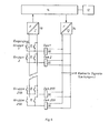
- FIG. 3 shows the manner in which the connection structure of the control with the machine 30 is constructed in the generic example considered here.
- Fig. 3 shows that the control unit 14 with memory 12 is obviously significantly smaller than the number of input and output modules, so that the latter modules represent the greater cost factor for the overall control.
- a further considerable expenditure provides the required compound of the input and output modules with the terminals of the control and the connection via multi-core cable with the K l Emmen box 32 of the engine 30 is. Comparing now the number of the input variables with the number of output variables, we obtain in the example discussed here, a ratio of 2: 1, which applies in most control cases, but the number of input variables can also slightly exceed that of the output variables by a factor of 4.
- the number of input variables which can be processed by means of a single input module 18 can be increased considerably if the selection of the input variable group to be connected to the input module is made in binary-coded form by the additional output module, that is, provided that the additional output module , as in the example discussed above, has 8 output variables, 256 different combinations can be switched. Since each input variable group has a maximum of 8 input variables, this results in a number of input variables of 2048 that can be processed by means of a single input module and a single additional output module.
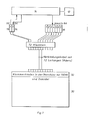
- the circuit arrangement shown in FIG. 6 has decoders 36 in the form of decoder cards.
- the cost of such decoder cards is 10 times lower than that of the input module cards, so that a considerable cost saving occurs.
- the decoder cards are, as can be seen from FIG. 7, which shows the circuit arrangement of FIG. 6 in a form connected to a machine 30, housed in the terminal box 32 of the machine.
Landscapes
- Engineering & Computer Science (AREA)
- Mechanical Engineering (AREA)
- General Engineering & Computer Science (AREA)
- Physics & Mathematics (AREA)
- General Physics & Mathematics (AREA)
- Automation & Control Theory (AREA)
- Feedback Control In General (AREA)
- Programmable Controllers (AREA)
Applications Claiming Priority (2)
| Application Number | Priority Date | Filing Date | Title |
|---|---|---|---|
| DE2950956 | 1979-12-18 | ||
| DE19792950956 DE2950956A1 (de) | 1979-12-18 | 1979-12-18 | Verfahren und schaltungsanordnung zum steuern einer vielzahl von ausgangsgroessen in abhaengigkeit von einer vielzahl von eingangsgroessen |
Publications (2)
| Publication Number | Publication Date |
|---|---|
| EP0031908A2 true EP0031908A2 (fr) | 1981-07-15 |
| EP0031908A3 EP0031908A3 (fr) | 1981-07-22 |
Family
ID=6088835
Family Applications (1)
| Application Number | Title | Priority Date | Filing Date |
|---|---|---|---|
| EP80107667A Withdrawn EP0031908A3 (fr) | 1979-12-18 | 1980-12-05 | Procédé et circuit pour commander plusieurs grandeurs de sortie en fonction de plusieurs grandeurs d'entrée |
Country Status (3)
| Country | Link |
|---|---|
| EP (1) | EP0031908A3 (fr) |
| JP (1) | JPS5694406A (fr) |
| DE (1) | DE2950956A1 (fr) |
Cited By (1)
| Publication number | Priority date | Publication date | Assignee | Title |
|---|---|---|---|---|
| EP0874089A2 (fr) | 1997-04-19 | 1998-10-28 | Hermann Dipl.-Ing. Diehl | Elément isolant et drainant en mousse de matière plastique rigide et procédé de son utilisation dans le sol |
Family Cites Families (1)
| Publication number | Priority date | Publication date | Assignee | Title |
|---|---|---|---|---|
| US4163387A (en) * | 1978-01-16 | 1979-08-07 | Schroeder Rondon L | Aircraft cabin display unit |
-
1979
- 1979-12-18 DE DE19792950956 patent/DE2950956A1/de not_active Withdrawn
-
1980
- 1980-12-05 EP EP80107667A patent/EP0031908A3/fr not_active Withdrawn
- 1980-12-18 JP JP17817180A patent/JPS5694406A/ja active Pending
Cited By (1)
| Publication number | Priority date | Publication date | Assignee | Title |
|---|---|---|---|---|
| EP0874089A2 (fr) | 1997-04-19 | 1998-10-28 | Hermann Dipl.-Ing. Diehl | Elément isolant et drainant en mousse de matière plastique rigide et procédé de son utilisation dans le sol |
Also Published As
| Publication number | Publication date |
|---|---|
| JPS5694406A (en) | 1981-07-30 |
| DE2950956A1 (de) | 1981-06-25 |
| EP0031908A3 (fr) | 1981-07-22 |
Similar Documents
| Publication | Publication Date | Title |
|---|---|---|
| DE3229988C2 (de) | Vorrichtung zum Steuern einer Presse mit Computersignalen | |
| DE19705570A1 (de) | Anordnung an einer Kontaktschiene | |
| DE4226704A1 (de) | Verfahren zum Betreiben einer Anlage mit mehreren an ein Bus-System angeschlossenen Komponenten und Schnittstellen-Schaltungsanordnung zur Durchführung des Verfahrens | |
| EP3251469B1 (fr) | Procédé pour faire fonctionner des appareils dans un système d'éclairage | |
| EP0853366A2 (fr) | Dispositif pour la transmission de signaux de commande à des vannes | |
| EP0113379B1 (fr) | Coupleur pour processeurs | |
| EP0031908A2 (fr) | Procédé et circuit pour commander plusieurs grandeurs de sortie en fonction de plusieurs grandeurs d'entrée | |
| DE4026581A1 (de) | Integriertes steuerungssystem fuer eine textilmaschine mit einer vielzahl von separat angetriebenen spindeln | |
| WO1999067538A1 (fr) | Unite modulaire d'une installation a air comprime | |
| DE1909032C3 (de) | Analog-Digitalwandler | |
| DE3853342T2 (de) | Schaltung für eine schnittstelle bei mechanischen anwendungen. | |
| DE102020000714A1 (de) | System | |
| DE3701919C1 (de) | Verfahren zur Reduzierung der Energieaufnahme einer Fernsprecheinrichtung,deren Versorgung mit elektrischer Energie ueber die Fernsprechleitung erfolgt,sowie Einrichtung zur Druchfuehrung des Verfahrens | |
| DE4414352C2 (de) | Einrichtung zum Verarbeiten von Daten, insbesondere zum Erfassen, Steuern und/oder Regeln von physikalischen Größen | |
| DE2825449C2 (de) | Statischer Rundsteuerempfänger | |
| EP0750802A1 (fr) | Armoire de distribution pour mettre des consommateurs electriques en et hors tension | |
| DE4137033A1 (de) | Speicherprogrammierbare steuerung | |
| EP4366275A1 (fr) | Système de communication modulaire et procédé de fonctionnement du système de communication | |
| DE2244934A1 (de) | Elektrisches schaltsystem fuer eine mehrzahl von verbrauchern | |
| DE2456999A1 (de) | Vorrichtung zur veraenderbaren verbindung von schaltelementen | |
| DE3439974C2 (de) | Schaltung zur wahlweisen Ansteuerung von zwei Stellgliedern | |
| DE19817024A1 (de) | Integrierte Schaltung | |
| DE2513153C3 (de) | Bausteinschaltung mit mehreren Verknüpfungsgliedern für unterschiedliche Verknüpfungsfunktionen | |
| DE3029033C2 (de) | Schaltungsanordnung | |
| DE1774093A1 (de) | Verfahren und Schnellschaltung zur Ansteuerung von Ausgabegeraeten |
Legal Events
| Date | Code | Title | Description |
|---|---|---|---|
| PUAI | Public reference made under article 153(3) epc to a published international application that has entered the european phase |
Free format text: ORIGINAL CODE: 0009012 |
|
| PUAL | Search report despatched |
Free format text: ORIGINAL CODE: 0009013 |
|
| AK | Designated contracting states |
Designated state(s): AT BE CH FR GB IT LU NL SE |
|
| AK | Designated contracting states |
Designated state(s): AT BE CH FR GB IT LU NL SE |
|
| STAA | Information on the status of an ep patent application or granted ep patent |
Free format text: STATUS: THE APPLICATION IS DEEMED TO BE WITHDRAWN |
|
| 18D | Application deemed to be withdrawn |
Effective date: 19820626 |
|
| RIN1 | Information on inventor provided before grant (corrected) |
Inventor name: WENINGER, KLAUS |