EP0031908A2 - Method and circuit for controlling a plurality of output values as a function of a plurality of input values - Google Patents
Method and circuit for controlling a plurality of output values as a function of a plurality of input values Download PDFInfo
- Publication number
- EP0031908A2 EP0031908A2 EP80107667A EP80107667A EP0031908A2 EP 0031908 A2 EP0031908 A2 EP 0031908A2 EP 80107667 A EP80107667 A EP 80107667A EP 80107667 A EP80107667 A EP 80107667A EP 0031908 A2 EP0031908 A2 EP 0031908A2
- Authority
- EP
- European Patent Office
- Prior art keywords
- input
- output
- variables
- module
- circuit arrangement
- Prior art date
- Legal status (The legal status is an assumption and is not a legal conclusion. Google has not performed a legal analysis and makes no representation as to the accuracy of the status listed.)
- Withdrawn
Links
Images


Classifications
-
- F—MECHANICAL ENGINEERING; LIGHTING; HEATING; WEAPONS; BLASTING
- F04—POSITIVE - DISPLACEMENT MACHINES FOR LIQUIDS; PUMPS FOR LIQUIDS OR ELASTIC FLUIDS
- F04C—ROTARY-PISTON, OR OSCILLATING-PISTON, POSITIVE-DISPLACEMENT MACHINES FOR LIQUIDS; ROTARY-PISTON, OR OSCILLATING-PISTON, POSITIVE-DISPLACEMENT PUMPS
- F04C2/00—Rotary-piston machines or pumps
- F04C2/08—Rotary-piston machines or pumps of intermeshing-engagement type, i.e. with engagement of co-operating members similar to that of toothed gearing
- F04C2/10—Rotary-piston machines or pumps of intermeshing-engagement type, i.e. with engagement of co-operating members similar to that of toothed gearing of internal-axis type with the outer member having more teeth or tooth-equivalents, e.g. rollers, than the inner member
- F04C2/107—Rotary-piston machines or pumps of intermeshing-engagement type, i.e. with engagement of co-operating members similar to that of toothed gearing of internal-axis type with the outer member having more teeth or tooth-equivalents, e.g. rollers, than the inner member with helical teeth
-
- G—PHYSICS
- G05—CONTROLLING; REGULATING
- G05B—CONTROL OR REGULATING SYSTEMS IN GENERAL; FUNCTIONAL ELEMENTS OF SUCH SYSTEMS; MONITORING OR TESTING ARRANGEMENTS FOR SUCH SYSTEMS OR ELEMENTS
- G05B19/00—Programme-control systems
- G05B19/02—Programme-control systems electric
- G05B19/04—Programme control other than numerical control, i.e. in sequence controllers or logic controllers
- G05B19/05—Programmable logic controllers, e.g. simulating logic interconnections of signals according to ladder diagrams or function charts
- G05B19/054—Input/output
-
- G—PHYSICS
- G05—CONTROLLING; REGULATING
- G05B—CONTROL OR REGULATING SYSTEMS IN GENERAL; FUNCTIONAL ELEMENTS OF SUCH SYSTEMS; MONITORING OR TESTING ARRANGEMENTS FOR SUCH SYSTEMS OR ELEMENTS
- G05B2219/00—Program-control systems
- G05B2219/10—Plc systems
- G05B2219/11—Plc I-O input output
- G05B2219/1125—I-O addressing
Definitions
- the invention relates to a method for controlling a large number of output variables as a function of a large number of input variables, in which the input variables are combined into input variable groups each comprising a certain number of input variables, the individual input variable groups are processed, in particular suppressed and suppressed, via an input filter with an input module to be assigned to each input variable group subjected to electrical isolation and level conversion, and fed to a freely programmable control unit and finally the output variables supplied by the control unit, combined into output variable groups, processed via an output amplifier with output modules assigned to each output variable group, in particular subjected to a level conversion and amplification, and then to one machine or the like to be output, and a circuit arrangement for controlling a plurality of output g depending on of a large number of input variables, with an input filter which processes the input variables combined to form a certain number of input variables and which has at least one input module to be assigned to each input variable group, preferably with an interference suppression unit, galvanic potential isolators such as optocouplers and level converter
- the invention has for its object to provide a method and a circuit arrangement of the generic type in which the number of input modules and thus the total effort for the control can be considerably reduced.
- this is achieved in a method of the type mentioned in the introduction in that the individual input variable groups are successively connected to an input module by means of at least one additional output module at the logically correct point in time defined by the control unit.
- a circuit arrangement according to the invention of the generic type is characterized by at least one additional output module, by means of which the individual input variable groups are successively in the the control unit defined, logically correct point in time can each be individually connected to an input module.
- the invention drastically reduces the number of input modules required, preferably down to one, while additionally only a further output module and possibly relatively inexpensive decoder cards are required.
- FIG. 1 in which a generic circuit arrangement is illustrated using the example of a pedestrian traffic light, input variables pass from a button "left” or “right”, which is shown schematically there, to an input filter 10, which is connected upstream of a control unit 14 interacting with a memory 12 . Via an output amplifier 16 connected downstream of the control unit 14, the output variables or command signals then reach the traffic lights “left” or “right” shown schematically in FIG. 1 below.
- the electronic freely programmable control described so far has a structure which is stored in the electronic memory 12, the content of which can be changed at any time, screens or paper recorders with keyboard, for example, being suitable in a known manner.
- the input filter 10 has a plurality of input modules 18 shown in FIG. 2.
- the input module 18 shown in FIG. 2 which can preferably be in the form of a plug-in card, is designed to process an input variable group of 8 input variables to be explained, an interference suppressor 20, a galvanic potential isolator 22 and a level converter 24 being provided for each input variable.
- a connector 26 to the input variables is shown on the left in FIG. 2, while a connector 28 to the control unit 14 (FIG. 1) is shown on the right.
- the galvanic potential isolator 22 consists, for example, of a known optocoupler, in which the input variable (the input signal) acts on a lamp, the light rays of which reach a transistor.
- the input filter 10 has the following tasks both in the generic circuit arrangement shown in FIGS. 1 and 2 and in the invention: First of all, the incoming input variables or input signals, which are often capacitive and inductive, particularly in a linked system Interference is subject to interference which could negatively affect the electronic control. In addition, galvanic electrical isolation is at least expedient, because the voltage level of the input variables is fixed to a certain, tolerable value, and if, due to a defect, a significantly higher voltage, for example of 380 volts, is applied to an input variable without one Electrical isolation could not only destroy the input filter, but the entire control system. Finally, the level conversion serves to adjust the signal level of the input variables, which must be at least 24 V DC for safety reasons, to the standard working voltage (logic voltage) of integrated circuits , namely 5 volts DC.
- the output amplifier 16 has a multiplicity of output modules which, in the exemplary embodiment shown, are each also suitable for processing a maximum of 8 output variables and are designed like a plug-in card.
- the output amplifier has the task of once performing a level conversion of the type described above for the input filter 10 in the reverse direction and also of amplifying the output variables, because namely the command signals that arrive from the integrated circuits of an electronic control are, for example, unable to to influence a valve or to switch a relay.
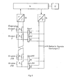
- FIG. 3 shows the manner in which the connection structure of the control with the machine 30 is constructed in the generic example considered here.
- Fig. 3 shows that the control unit 14 with memory 12 is obviously significantly smaller than the number of input and output modules, so that the latter modules represent the greater cost factor for the overall control.
- a further considerable expenditure provides the required compound of the input and output modules with the terminals of the control and the connection via multi-core cable with the K l Emmen box 32 of the engine 30 is. Comparing now the number of the input variables with the number of output variables, we obtain in the example discussed here, a ratio of 2: 1, which applies in most control cases, but the number of input variables can also slightly exceed that of the output variables by a factor of 4.
- the number of input variables which can be processed by means of a single input module 18 can be increased considerably if the selection of the input variable group to be connected to the input module is made in binary-coded form by the additional output module, that is, provided that the additional output module , as in the example discussed above, has 8 output variables, 256 different combinations can be switched. Since each input variable group has a maximum of 8 input variables, this results in a number of input variables of 2048 that can be processed by means of a single input module and a single additional output module.
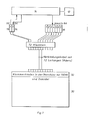
- the circuit arrangement shown in FIG. 6 has decoders 36 in the form of decoder cards.
- the cost of such decoder cards is 10 times lower than that of the input module cards, so that a considerable cost saving occurs.
- the decoder cards are, as can be seen from FIG. 7, which shows the circuit arrangement of FIG. 6 in a form connected to a machine 30, housed in the terminal box 32 of the machine.
Landscapes
- Engineering & Computer Science (AREA)
- Mechanical Engineering (AREA)
- General Engineering & Computer Science (AREA)
- Physics & Mathematics (AREA)
- General Physics & Mathematics (AREA)
- Automation & Control Theory (AREA)
- Feedback Control In General (AREA)
- Programmable Controllers (AREA)
Abstract
Verfahren und Schaltungsanordnung zum Steuern einer Vielzahl von Ausgangsgrößen in Abhängigkeit von einer Vielzahl von Eingangsgrößen, bei dem die Eingangsgrößen zu jeweils eine bestimmte Anzahl von Eingangsgrößen umfassenden Eingangsgrößengruppen zusammengefaßt, die einzelnen Eingangsgrößengruppen über ein Eingangsfilter mit jeder Eingangsgrößengruppe zuzuordnender Eingabebaugruppe aufgearbeitet, insbesondere entstört und einer galvanischen Potentialtrennung sowie einer Pegelumsetzung unterworfen, und einer freiprogrammierbaren Steuereinheit zugeführt und schließlich die von der Steuereinheit gelieferten Ausgangsgrößen, zu Ausgangsgrößengruppen zusammengefaßt, über einen Ausgangsverstärker mit jeder Ausgangsgrößengruppe zugeordneter Ausgabebaugruppe aufbereitet, insbesondere einer Pegelumsetzung sowie einer Verstärkung unterworfen, und daraufhin an eine zu steuernde Maschine oder dergleichen ausgegeben werden, wobei die einzelnen Eingangsgrößengruppen mittels wenigstens einer zusätzlichen Ausgabebaugruppe aufeinanderfolgend im durch die Steuereinheit definierten, jeweils logisch richtigen Zeitpunkt jeweils einzeln an eine Eingabebaugruppe angeschaltet werden.Method and circuit arrangement for controlling a large number of output variables as a function of a large number of input variables, in which the input variables are combined into input variable groups comprising a certain number of input variables, the individual input variable groups are processed, in particular suppressed, and galvanically, with an input module to be assigned to each input variable group Potential isolation and level conversion, and fed to a freely programmable control unit and finally the output variables supplied by the control unit, combined into output variable groups, processed via an output amplifier with output modules assigned to each output variable group, in particular subjected to a level conversion and amplification, and then to a machine or to be controlled The like are output, the individual input variable groups by means of at least one additional Chen output module are sequentially connected to an input module individually at the logically correct point in time defined by the control unit.
Description
Die Erfindung betrifft ein Verfahren zum Steuern einer Vielzahl von Ausgangsgrößen in Abhängigkeit von einer Vielzahl von Eingangsgrößen, bei dem die Eingangsgrößen zu jeweils eine bestimmte Anzahl von Eingangsgrößen umfassenden Eingangsgrößengruppen zusammengefaßt, die einzelnen Eingangsgrößengruppen über ein Eingangsfilter mit jeder Eingangsgrößengruppe zuzuordnender Eingabebaugruppe aufgearbeitet, insbesondere entstört und einer galvanischen Potentialtrennung sowie einer Pegelumsetzung unterworfen, und einer freiprogrammierbaren Steuereinheit zugeführt und schließlich die von d/er Steuereinheit gelieferten Ausgangsgrößen, zu Ausgangsgrößengruppen zusammengefaßt, über einen Ausgangsverstärker mit jeder Ausgangsgrößengruppe zugeordneter Ausgabebaugruppe aufbereitet, insbesondere einer Pegelumsetzung sowie einer Verstärkung unterworfen, und daraufhin an eine zu steuernde Maschine oder dergleichen ausgegeben werden, sowie eine Schaltungsanordnung zum Steuern einer Vielzahl von Ausgangsgrößen in Abhängigkeit von einer Vielzahl von Eingangsgrößen, mit einem die zu jeweils eine bestimmte Anzahl von Eingangsgrößen umfassenden Eingangsgrößengruppen zusammengefaßten Eingangsgrößen aufarbeitenden Eingangsfilter, welches mindestens eine jeder Eingangsgrößengruppe zuzuordnende Eingabebaugruppe, vorzugsweise mit Entstöreinheit, galvanischem Potentialtrenner, wie Optokoppler, und Pegelumsetzer, aufweist, einer freiprogrammierbaren Steuereinheit und einem Ausgangsverstärker, der für jede aus einer bestimmten Anzahl zusammengefaßter Ausgangsgrößen bestehende Ausgangsgrößengruppe eine Ausgabebaugruppe, vorzugsweise mit Pegelumsetzer und Verstärker, aufweist.The invention relates to a method for controlling a large number of output variables as a function of a large number of input variables, in which the input variables are combined into input variable groups each comprising a certain number of input variables, the individual input variable groups are processed, in particular suppressed and suppressed, via an input filter with an input module to be assigned to each input variable group subjected to electrical isolation and level conversion, and fed to a freely programmable control unit and finally the output variables supplied by the control unit, combined into output variable groups, processed via an output amplifier with output modules assigned to each output variable group, in particular subjected to a level conversion and amplification, and then to one machine or the like to be output, and a circuit arrangement for controlling a plurality of output g depending on of a large number of input variables, with an input filter which processes the input variables combined to form a certain number of input variables and which has at least one input module to be assigned to each input variable group, preferably with an interference suppression unit, galvanic potential isolators such as optocouplers and level converters, a freely programmable control unit and an output amplifier, which has an output module, preferably with a level converter and amplifier, for each output variable group consisting of a certain number of combined output variables.
Bisher ist es in freiprogrammierbaren Steuerungen der gattungsgemäßen Art erforderlich, für jede der eine bestimmte Anzahl von Eingangsgrößen umfassenden Eingangsgrößengruppen jeweils eine Eingabebaugruppe vorzusehen, wobei also die einzelnen Eingabebaugruppen ihre Informationen der Steuereinheit parallel zueinander ständig anbieten, obwohl die Steuereinheit nur in der Lage ist, in einem bestimmten Arbeitsschritt oder Arbeitszyklus eine einzige Eingabebaugruppe abzufragen. Der durch die Vielzahl von Eingabebaugruppen notwendige Kostenaufwand ist, insbesondere auch unter Berücksichtigung der erforderlichen Verkabelung etc., beträchtlich.So far, it has been necessary in freely programmable controls of the generic type to provide an input module for each of the input variable groups comprising a certain number of input variables, the individual input modules therefore constantly offering their information to the control unit in parallel with one another, although the control unit is only able to query a single input module for a specific work step or work cycle. The cost involved due to the large number of input modules is considerable, especially taking into account the necessary cabling, etc.
Der Erfindung liegt die Aufgabe zugrunde, ein Verfahren sowie eine Schaltungsanordnung der gattungsgemäßen Art zu schaffen, bei der die Zahl der Eingabebaugruppen und damit der Gesamtaufwand für die Steuerung beträchtlich vermindert werden können.The invention has for its object to provide a method and a circuit arrangement of the generic type in which the number of input modules and thus the total effort for the control can be considerably reduced.
Erfindungsgemäß wird dies bei einem Verfahren der eingangs genannten Art dadurch gelöst, daß d ie einzelnen Eingangsgrößengruppen mittels wenigstens einer zusätzlichen Ausgabebaugruppe aufeinanderfolgend im durch die Steuereinheit definierten, jeweils logisch richtigen Zeitpunkt jeweils einzeln an eine Eingabebaugruppe angeschaltet werden.According to the invention, this is achieved in a method of the type mentioned in the introduction in that the individual input variable groups are successively connected to an input module by means of at least one additional output module at the logically correct point in time defined by the control unit.
Eine erfindungsgemäße Schaltungsanordnung der gattungsgemäßen Art ist gekennzeichnet durch wenigstens eine zusätzliche Ausgabebaugruppe, mittels welcher die einzelnen Eingangsgrößengruppen aufeinanderfolgend im durch die Steuereinheit definierten, jeweils logisch richtigen Zeitpunkt jeweils einzeln an eine Eingabebaugruppe anschaltbar sind.A circuit arrangement according to the invention of the generic type is characterized by at least one additional output module, by means of which the individual input variable groups are successively in the the control unit defined, logically correct point in time can each be individually connected to an input module.
Besonders bevorzugte Ausführungsformen des Verfahrens sowie der Schaltungsanordnung nach der Erfindung ergeben sich aus den jeweiligen Unteransprüchen, wobei insbesondere vorgesehen sein kann, daß lediglich eine einzige Eingabebaugruppe in Verbindung mit einer einzigen zusätzlichen Ausgabebaugruppe Verwendung findet, welch letztere in besonders vorteilhafter Weise als Binärkodierer für die anzuschaltenden Eingangsgrößengruppen arbeitet.Particularly preferred embodiments of the method and of the circuit arrangement according to the invention result from the respective subclaims, it being possible in particular to provide that only a single input module is used in conjunction with a single additional output module, the latter in a particularly advantageous manner as a binary encoder for those to be connected Input size groups works.
Demzufolge wird durch die Erfindung die Anzahl der erforderlichen Eingabebaugruppen drastisch reduziert, vorzugsweise bis auf eine, während zusätzlich lediglich eine weitere Ausgabebaugruppe sowie gegebenenfalls verhältnismäßig preiswerte Dekoderkarten erforderlich sind.Accordingly, the invention drastically reduces the number of input modules required, preferably down to one, while additionally only a further output module and possibly relatively inexpensive decoder cards are required.
Weitere Merkmale und Vorteile der Erfindung ergeben sich aus den Ansprüchen und aus der nachfolgenden Beschreibung, in der zwei Ausführungsbeispiele anhand der schematischen Zeichnung im einzelnen erläutert sind. Dabei zeigt:
- Fig. 1 eine Schaltungsanordnung der gattungsgemäßen Art in Diagrammdarstellung;
- Fig. 2 eine Eingabebaugruppe des Eingangsfilters der Schaltungsanordnung von Fig. 1 in Diagrammdarstellung;
- Fig. 3 eine Übersicht über den Aufbau der gattungsgemäßen Schaltungsanordnung von Fig. 1 und Fig. 2 mit dem Anschluß an eine zu steuernde Maschine;
- Fig. 4 in diagrammartiger Darstellung das Abfragen der verschiedenen Eingabebaugruppen des Eingangsfilters der gattungsgemäßen Schaltungsanordnung von Fig. 1 bis Fig. 3;
- Fig. 5 ein erstes Ausführungsbeispiel einer erfindungsgemäßen Schaltungsanordnung in Diagrammdarstellung;
- Fig. 6 ein zweites Ausführungsbeispiel einer Schaltungsanordnung nach der Erfindung in Diagrammdarstellung;
- Fig. 7 das Ausführungsbeispiel vonFig. 6 in Verbindung mit einer zu steuernden Maschine.
- Fig. 1 shows a circuit arrangement of the generic type in a diagram;
- FIG. 2 shows an input module of the input filter of the circuit arrangement from FIG. 1 in a diagram;
- 3 shows an overview of the structure of the generic circuit arrangement of FIGS. 1 and 2 with the connection to a machine to be controlled;
- 4 shows, in a diagrammatic representation, the interrogation of the various input modules of the input filter of the generic circuit arrangement from FIGS. 1 to 3;
- 5 shows a first exemplary embodiment of a circuit arrangement according to the invention in a diagram;
- 6 shows a second exemplary embodiment of a circuit arrangement according to the invention in a diagram;
- Fig. 7 shows the embodiment of Fig. 6 in connection with a machine to be controlled.
Wie Fig. 1 zeigt, bei der eine gattungsgemäße Schaltungsanordnung am Beispiel einer Fußgängerampel dargestellt ist, gelangen Eingangsgrößen von einem dort schematisch wiedergegebenen Taster "links" bzw. "rechts" zu einem Eingangsfilter 10, welches einer mit einem Speicher 12 zusammenwirkenden Steuereinheit 14 vorgeschaltet ist. Über einen der Steuereinheit 14 nachgeschalteten Ausgangsverstärker 16 gelangen dann die Ausgabegrößen oder Befehlssignale an die in Fig. 1 unten schematisch gezeigten Ampeln "links" bzw. "rechts".As shown in FIG. 1, in which a generic circuit arrangement is illustrated using the example of a pedestrian traffic light, input variables pass from a button "left" or "right", which is shown schematically there, to an
Die insoweit beschriebene elektronische freiprogrammierbare Steuerung hat eine Struktur, die in dem elektronischen Speicher 12 abgelegt ist, dessen Inhalt jederzeit verändert werden kann, wobei in bekannter Weise als Programmiergeräte beispielsweise Bildschirme oder Blattschreiber mit Tastatur geeignet sind. Das Eingangsfilter 10 weist eine Vielzahl von in Fig. 2 gezeigten Eingabebaugruppen 18 auf. Die in Fig. 2 gezeigte Eingabebaugruppe 18, die vorzugsweise die Form einer Steckkarte haben kann, ist zur Verarbeitung einer noch zu erläuternden Eingangsgrößengruppe von 8 Eingangsgrößen ausgebildet, wobei für jede Eingangsgröße eine Entstöreinheit 20, ein galvanischer Potentialtrenner 22 und ein Pegelumsetzer 24 vorgesehen sind. Links ist in Fig. 2 ein Stecker 26 zu den Eingangsgrößen gezeigt, während rechts ein Stecker 28 zur Steuerungseinheit 14 (Fig. 1) dargestellt ist. Der galvanische Potentialtrenner 22 besteht beispielsweise aus einem bekannten Optokoppler, bei dem die Eingangsgröße (das Eingangssignal) eine Lampe beaufschlagt, deren Lichtstrahlen auf einen Transistor gelangen.The electronic freely programmable control described so far has a structure which is stored in the
Insgesamt hat das Eingangsfilter 10 sowohl bei der in Fig. 1 und 2 wiedergegebenen gattungsgemäßen Schaltungsanordnung als auch bei der Erfindung somit die folgenden Aufgaben: Zunächst einmal sollen die ankommenden Eingangsgrößen oder Eingangssignale, die insbesondere in einer verketteten Anlage häufig kapazitiven und induktiven Störeinflüssen unterliegen, welche die elektronische Steuerung negativ.beeinflussen könnten, entstört werden. Außerdem ist eine galvanische Potentialtrennung zumindest zweckmäßig, weil nämlich die Spannungshöhe der Eingangsgrößen auf eine bestimmte, in Grenzen tolerierbare Größe festgelegt ist, wobei dann, wenn infolge eines Defektes eine wesentlich höhere Spannung, beispielsweise von 380 Volt, an eine Eingangsgröße angelegt wird, ohne eine galvanische "Potentialtrennung nicht nur das Eingangsfilter, sondern die gesamte Steuerung zerstört werden könnte. Schließlich dient die Pegelumsetzung dazu, die Signalhöhe der Eingangsgrößen, die aus Sicherheitsgründen mindestens 24 Volt Gleichspannung bet/ragen muß, auf die Standard-Arbeitsspannung (Logikspannung) von integrierten Schaltkreisen, nämlich 5 Volt Gleichspannung, umzusetzen.Overall, the
Der Ausgangsverstärker 16 weist in ähnlicher Weise wie das Eingangsfilter 10 eine Vielzahl von Ausgabebaugruppen auf, die ebenfalls, beim gezeigten Ausführungsbeispiel, jeweils zur Verarbeitung von maximal 8 Ausgangsgrößen geeignet und steckkartenartig ausgebildet sind. Der Ausgangsverstärker hat die Aufgabe, einmal eine Pegelumsetzung der vorstehend für das Eingangsfilter 10 beschriebenen Art in umgekehrter Richtung durchzuführen und außerdem die Ausgangsgrößen zu verstärken, weil nämlich die Befehlssignale, die aus den integrierten Schaltkreisen einer elektronischen Steuerung ankommen, beispielsweise nicht in der Lage sind, ein Ventil zu beeinflussen oder ein Relais zu schalten.In a manner similar to the
Wichtig ist, daß sowohl im Eingangsfilter 10 als auch im Ausgangsverstärker 16 jeweils eine Wirkungskette für jede Eingangsgröße bzw. jede Ausgangsgröße vorgesehen sein muß, so daß man also vereinfacht sagen kann, daß für jede Eingangsgröße ein spezielles Eingangsfilter und für jede Ausgangsgröße ein spezieller Ausgangsverstärker erforderlich sind:
- Als Beispiel sei angenommen, daß die Zahl der Eingangsgrößen 100 und die Zahl der Ausgangsgrößen 50 beträgt, wobei also dann mittels der Steuerung oder Schaltungsanordnung 100 Eingangsgrößen und 50 Ausgangsgrößen verarbeitet werden müssen. Die Anzahl der Eingangsgrößen kann dabei im übrigen, je nach Anforderung, bis zu 1000 und mehr pro Steuerung steigen. Die Eingangs- und Ausgangsgrößen befinden sich alle in einer
Maschine 30, deren Ablauf (Steuerkette) automatisch kontrolliert werden soll. Werden nunEingangsbaugruppen 18 für dasEingangsfilter 10 verwendet, die zur Verarbeitung von jeweils 8 Eingangsgrößen geeignet sind, und verwendet man analoge Ausgabebaugruppen für denAusgangsverstärker 16, wobei sowohl dieEingangsbaugruppen 18 als auch die Ausgangsbaugruppen die Form von Steckkarten im Standard-Europaformat haben können, also mit einer Länge von 160 mm und einer Breite von 100 mm, so ist es offensichtlich erforderlich, eine Anzahl von Eingangsbaugruppen und Ausgangsbaugruppen zu verwenden, die sich zu einem Achtel des der Anzahl der Eingangsgrößen bzw. der Ausgangsgrößen nächsthöheren Vielfachen von 8 ergibt. Bei dem hier gebrachten Beispiel sind somit 13Eingabebaugruppen 18 sowie 7 Ausgabebaugruppen notwendig.
- As an example, assume that the number of input variables is 100 and the number of output variables is 50, so that 100 input variables and 50 output variables must then be processed by means of the control or circuit arrangement. The number of input variables can Incidentally, depending on the requirement, up to 1000 and more increase per control. The input and output variables are all located in one
machine 30, the sequence (control chain) of which is to be checked automatically. Ifinput modules 18 are now used for theinput filter 10, which are suitable for processing 8 input variables in each case, and analog output modules are used for theoutput amplifier 16, both theinput modules 18 and the output modules can have the form of plug-in cards in the standard European format, i.e. with a length of 160 mm and a width of 100 mm, it is obviously necessary to use a number of input modules and output modules that result in an eighth of the next higher multiple of 8 to the number of input variables or output variables. In the example given here, 13input modules
In Fig. 3 ist dargestellt, auf welche Weise bei dem hier betrachteten gattungsgemäßen Beispiel die Verbindungsstruktur der Steuerung mit der Maschine 30 aufgebaut ist. Fig. 3 läßt erkennen, daß die Steuereinheit 14 mit Speicher 12 offensichtlich wesentlich kleiner als die Anzahl der Ein- und Ausgabebaugruppen ist, so daß also die letztgenannten Baugruppen den größeren Kostenfaktor für die Gesamtsteuerung darstellen. Einen weiteren beträchtlichen Aufwand stellt die erforderliche Verbindung der Ein- und Ausgabebaugruppen mit den Klemmen der Steuerung und die Verbindung über Vieladerkabel mit dem Klemmenkasten 32 der Maschine 30 dar. Vergleicht man nun die Anzahl der Eingangsgrößen mit der Anzahl der Ausgangsgrößen, so ergibt sich beim hier diskutierten Beispiel ein Verhältnis von 2:1, welches in den meisten Steuerungsfällen zutrifft, wobei aber die Anzahl der Eingangsgrößen diejenige der Ausgangsgrößen auch leicht um denFaktor 4 übersteigen kann. Dies würde also bedeuten, bei einer Anzahl von 200 Eingangsgrößen nämlich, daß 26 Eingabebaugruppen, 250 Klemmen und ein Verbindungskabel mit 250 Adern erforderlich wären. Eingehende Untersuchungen haben gezeigt, daß in den meisten Anwendungsbeispielen die Anzahl der Eingangsgrößen mindestens um den Faktor 2 größer als diejenige der Ausgangsgrößen ist. In Fig. 4 ist im übrigen gezeigt, auf welche Weise die einzelnen Eingabebaugruppen 18 die durch sie verarbeiteten Eingangsgrößen an die Steuereinheit 14 beim Stand der Technik abgeben: Die Eingangsbaugruppen 18 bieten ihre Informationen der Steuereinheit 14 zwar ständig parallel an, jedoch ist die Steuereinheit 14 pro Arbeitszyklus nur in der Lage, Eingangsgrößen von einer einzigen Eingabebaugruppe 18 zu verarbeiten, wobei dasselbe im übrigen auch für die Ausgabebaugruppen zutrifft. Dementsprechend werden, wie Fig. 4 schematisch erkennen läßt, die einzelnen Eingabebaugruppen 18 des Eingangsfilters 10 nacheinander durch die Steuereinheit 14 abgefragt.3 shows the manner in which the connection structure of the control with the
Bei der erfindungsgemäßen Schaltungsanordnung bzw. bei dem erfindungsgemäßen Verfahren, dem ersten Ausführungsbeispiel entsprechend, wie es in Fig. 5 wiedergegeben ist, wird nun so vorgegangen, daß die Eingangsgrößen zu Eingangsgrößengruppen von jeweils höchstens - beim gezeigten Ausführungsbeispiel - 8 einzelnen Eingangsgrößen zusammengefaßt werden. Die Eingangsgrößengruppen 1 bis 4, die in Fig. 5 wiedergegeben sind, werden im jeweils logisch richtigen Zeitpunkt mittels einer zusätzlichen Ausgabebaugruppe 34 durch die Steuereinheit 14 selbst an eine einzige Eingabebaugruppe 18 angeschaltet, so daß also hier nicht parallel zueinander eine Vielzahl von Eingabebaugruppen notwendig ist, sondern lediglich eine einzige Eingabebaugruppe 18, die, wie gesagt, im jeweils logisch richtigen Zeitpunkt durch die Steuereinheit 14 angeschaltet wird. Hierzu ist es lediglich erforder- lich, eine einzige zusätzliche Ausgabebaugruppe 34 vorzusehen. Die Schaltungsanordnung von Fig. 5 arbeitet also in der Weise, daß zunächst alle Eingangsgrößen in unabhängige Eingangsgrößengruppen von 8 oder weniger Signalen aufgeteilt werden. Zum logisch notwendigen und richtigen Zeitpunkt wird jeweils eine Eingangsgrößengruppe durch die Steuereinheit 14 an die einzige Eingabebaugruppe 18 angeschaltet, so daß also die entsprechenden Signalzustände der betreffenden Eingangsgrößengruppe in die Steuereinheit 14 eingelesen werden können. Im Anschluß hieran wird die vorher aktivierte Eingangsgrößengruppe durch die Steuereinheit 14 sofort wieder von der Eingabebaugruppe 18 abgeschaltet. Enthält die verwendete zusätzliche Ausgabebaugruppe, wie bei der oben diskutierten gattungsgemäßen Schaltungsanordnung von Fig. 1 bis Fig. 4, 8 Ausgangsgrößen, so lassen sich also mittels des in Fig. 5 gezeigten Ausführungsbeispieles 8 verschiedene Eingangsgrößengruppen mit jeweils 8 Eingangsgrößen an die einzige vorhandene Eingabebaugruppe 18 anschalten, also maximal 64 Eingangsgrößen.In the circuit arrangement according to the invention or in the method according to the invention, corresponding to the first exemplary embodiment, as shown in FIG. 5, the procedure is now such that the input variables are combined into input variable groups of at most - in the exemplary embodiment shown - 8 individual input variables. The
Wie in Fig. 6 gezeigt ist, läßt sich die Anzahl der mittels einer einzigen Eingabebaugruppe 18 verarbeitbaren Eingangsgrößen noch beträchtlich erhöhen, wenn die Auswahl der jeweils an die Eingabebaugruppe anzuschaltenden Eingangsgrößengruppe durch die zusätzliche Ausgabebaugruppe in binärkodierter Form erfolgt, wobei also, sofern die zusätzliche Ausgabebaugruppe, wie beim oben diskutierten Beispiel, 8 Ausgangsgrößen aufweist, 256 verschiedene Kombinationen schaltbar sind. Da jede Eingangsgrößengruppe maximal 8 Eingangsgrößen aufweist, ergibt sich hieraus eine Anzahl von mittels einer einzigen Eingabebaugruppe und einer einzigen zusätzlichen Ausgabebaugruppe verarbeitbaren Eingangsgrößen von 2048.As shown in FIG. 6, the number of input variables which can be processed by means of a
Um die kodierten Informationen dekodieren zu können, weist die in Fig. 6 gezeigte Schaltungsanordnung Dekoder 36 in Form von Dekoderkarten auf. Der Kostenaufwand derartiger Dekoderkarten ist aber um den Faktor 10 niedriger als der der Eingabebaugruppen-Karten, so daß eine beträchtliche Kostenersparnis auftritt.In order to be able to decode the coded information, the circuit arrangement shown in FIG. 6 has
Die Dekoderkarten werden im übrigen, wie aus Fig. 7 ersichtlich, welche die Schaltungsanordnung von Fig. 6 in an eine Maschine 30 angeschlossener Form zeigt, im Klemmenkasten 32 der Maschine untergebracht.The decoder cards are, as can be seen from FIG. 7, which shows the circuit arrangement of FIG. 6 in a form connected to a
Beim vorstehend beschriebenen Beispiel lassen sich also von den 13 ansonsten, nämlich beim Stand der Technik, notwendigen Eingabebaugruppen 18 zwölf einsparen. Nimmt man ein Verhältnis von Eingangsgrößen zu Ausgangsgrößen von 4 : 1 an, so sind bereits 25 Eingabebaugruppen eingespart. Während bei einer Steuerung von 1000 Eingangsgrößen beim herkömmlichen System 125 Eingabebaugruppen, 1000 Klemmen und 1000 Leitungen (Adern) erforderlich sind, sind erfindungsgemäß lediglich eine einzige Eingabebaugruppe, eine einzige Ausgabebaugruppe, 125 Dekoder, 16 Klemmen und 16 Adern notwendig. Die Anzahl der Ausgabebaugruppen ist natürlich, abgesehen von der zusätzlichen Ausgabebaugruppe 34, in beiden Fällen gleich.In the example described above, twelve of the 13
Die in der vorstehenden Beschreibung, in der Zeichnung und in den Ansprüchen offenbarten Merkmale der Erfindung können sowohl einzeln als auch in beliebigen Kombinationen für die Verwirklichung der Erfindung in ihren verschiedenen Ausführungsformen wesentlich sein.The features of the invention disclosed in the above description, in the drawing and in the claims can be essential both individually and in any combination for realizing the invention in its various embodiments.
Claims (18)
Applications Claiming Priority (2)
| Application Number | Priority Date | Filing Date | Title |
|---|---|---|---|
| DE2950956 | 1979-12-18 | ||
| DE19792950956 DE2950956A1 (en) | 1979-12-18 | 1979-12-18 | METHOD AND CIRCUIT ARRANGEMENT FOR CONTROLLING A VARIETY OF OUTPUT SIZES DEPENDING ON A VARIETY OF INPUT SIZES |
Publications (2)
| Publication Number | Publication Date |
|---|---|
| EP0031908A2 true EP0031908A2 (en) | 1981-07-15 |
| EP0031908A3 EP0031908A3 (en) | 1981-07-22 |
Family
ID=6088835
Family Applications (1)
| Application Number | Title | Priority Date | Filing Date |
|---|---|---|---|
| EP80107667A Withdrawn EP0031908A3 (en) | 1979-12-18 | 1980-12-05 | Method and circuit for controlling a plurality of output values as a function of a plurality of input values |
Country Status (3)
| Country | Link |
|---|---|
| EP (1) | EP0031908A3 (en) |
| JP (1) | JPS5694406A (en) |
| DE (1) | DE2950956A1 (en) |
Cited By (1)
| Publication number | Priority date | Publication date | Assignee | Title |
|---|---|---|---|---|
| EP0874089A2 (en) | 1997-04-19 | 1998-10-28 | Hermann Dipl.-Ing. Diehl | Insulation and drainage element made from a hard foam material and method of using the element in the ground |
Family Cites Families (1)
| Publication number | Priority date | Publication date | Assignee | Title |
|---|---|---|---|---|
| US4163387A (en) * | 1978-01-16 | 1979-08-07 | Schroeder Rondon L | Aircraft cabin display unit |
-
1979
- 1979-12-18 DE DE19792950956 patent/DE2950956A1/en not_active Withdrawn
-
1980
- 1980-12-05 EP EP80107667A patent/EP0031908A3/en not_active Withdrawn
- 1980-12-18 JP JP17817180A patent/JPS5694406A/en active Pending
Cited By (1)
| Publication number | Priority date | Publication date | Assignee | Title |
|---|---|---|---|---|
| EP0874089A2 (en) | 1997-04-19 | 1998-10-28 | Hermann Dipl.-Ing. Diehl | Insulation and drainage element made from a hard foam material and method of using the element in the ground |
Also Published As
| Publication number | Publication date |
|---|---|
| JPS5694406A (en) | 1981-07-30 |
| DE2950956A1 (en) | 1981-06-25 |
| EP0031908A3 (en) | 1981-07-22 |
Similar Documents
| Publication | Publication Date | Title |
|---|---|---|
| DE3229988C2 (en) | Device for controlling a press with computer signals | |
| DE19705570A1 (en) | Arrangement on a contact rail | |
| DE4226704A1 (en) | Controlling and activating bus coupled components eg car radio CD player etc. - has components coupled by interface units onto bus with wake up circuit periodically operated | |
| EP3251469B1 (en) | Method for operating devices in a lighting system | |
| EP0853366A2 (en) | Device for transmission of control signals to valves | |
| EP0113379B1 (en) | Coupler for processors | |
| EP0031908A2 (en) | Method and circuit for controlling a plurality of output values as a function of a plurality of input values | |
| DE4026581A1 (en) | Multi-spindle textile machine control - has slide register at each spindle linked to bus computer at central computer | |
| WO1999067538A1 (en) | Module for a compressed-air installation | |
| DE1909032C3 (en) | Analog-to-digital converter | |
| DE3853342T2 (en) | CIRCUIT FOR AN INTERFACE IN MECHANICAL APPLICATIONS. | |
| DE102020000714A1 (en) | system | |
| DE3701919C1 (en) | Method for reducing the energy consumption of a telephone device, the supply of which is supplied with electrical energy via the telephone line, and device for carrying out the method | |
| DE4414352C2 (en) | Device for processing data, in particular for capturing, controlling and / or regulating physical quantities | |
| DE2825449C2 (en) | Static ripple control receiver | |
| EP0750802A1 (en) | Switching distributor for switching electric consumers on and off | |
| DE4137033A1 (en) | PROGRAMMABLE CONTROL | |
| EP4366275A1 (en) | Modular communication system and method for operating the communication system | |
| DE2244934A1 (en) | ELECTRIC SWITCHING SYSTEM FOR A MULTIPLE CONSUMERS | |
| DE2456999A1 (en) | DEVICE FOR THE CHANGIBLE CONNECTION OF SWITCHING ELEMENTS | |
| DE3439974C2 (en) | Circuit for the optional control of two actuators | |
| DE19817024A1 (en) | Integrated circuit | |
| DE2513153C3 (en) | Block circuit with several logic elements for different logic functions | |
| DE3029033C2 (en) | Circuit arrangement | |
| DE1774093A1 (en) | Method and quick connection for controlling output devices |
Legal Events
| Date | Code | Title | Description |
|---|---|---|---|
| PUAI | Public reference made under article 153(3) epc to a published international application that has entered the european phase |
Free format text: ORIGINAL CODE: 0009012 |
|
| PUAL | Search report despatched |
Free format text: ORIGINAL CODE: 0009013 |
|
| AK | Designated contracting states |
Designated state(s): AT BE CH FR GB IT LU NL SE |
|
| AK | Designated contracting states |
Designated state(s): AT BE CH FR GB IT LU NL SE |
|
| STAA | Information on the status of an ep patent application or granted ep patent |
Free format text: STATUS: THE APPLICATION IS DEEMED TO BE WITHDRAWN |
|
| 18D | Application deemed to be withdrawn |
Effective date: 19820626 |
|
| RIN1 | Information on inventor provided before grant (corrected) |
Inventor name: WENINGER, KLAUS |