EP0031748B2 - Verfahren und Vorrichtung zum Prüfen von Fahrzeugrädern - Google Patents
Verfahren und Vorrichtung zum Prüfen von Fahrzeugrädern Download PDFInfo
- Publication number
- EP0031748B2 EP0031748B2 EP80401772A EP80401772A EP0031748B2 EP 0031748 B2 EP0031748 B2 EP 0031748B2 EP 80401772 A EP80401772 A EP 80401772A EP 80401772 A EP80401772 A EP 80401772A EP 0031748 B2 EP0031748 B2 EP 0031748B2
- Authority
- EP
- European Patent Office
- Prior art keywords
- rim
- wheel
- jacks
- forces
- fact
- Prior art date
- Legal status (The legal status is an assumption and is not a legal conclusion. Google has not performed a legal analysis and makes no representation as to the accuracy of the status listed.)
- Expired
Links
- 238000012360 testing method Methods 0.000 title claims description 19
- 238000000034 method Methods 0.000 title description 3
- 238000001228 spectrum Methods 0.000 claims description 9
- 239000012530 fluid Substances 0.000 claims description 2
- 238000010998 test method Methods 0.000 claims description 2
- 238000012544 monitoring process Methods 0.000 claims 2
- 230000003213 activating effect Effects 0.000 claims 1
- 230000006870 function Effects 0.000 claims 1
- 239000011324 bead Substances 0.000 description 7
- 238000011161 development Methods 0.000 description 3
- 238000009434 installation Methods 0.000 description 3
- 238000004804 winding Methods 0.000 description 3
- 230000000694 effects Effects 0.000 description 2
- 210000002445 nipple Anatomy 0.000 description 2
- 238000004088 simulation Methods 0.000 description 2
- 230000003068 static effect Effects 0.000 description 2
- 230000001360 synchronised effect Effects 0.000 description 2
- 241001080024 Telles Species 0.000 description 1
- 230000006399 behavior Effects 0.000 description 1
- 238000005452 bending Methods 0.000 description 1
- 238000012937 correction Methods 0.000 description 1
- 238000010586 diagram Methods 0.000 description 1
- 238000010438 heat treatment Methods 0.000 description 1
- 230000003100 immobilizing effect Effects 0.000 description 1
- 230000002093 peripheral effect Effects 0.000 description 1
- 230000002787 reinforcement Effects 0.000 description 1
- 230000000717 retained effect Effects 0.000 description 1
- 238000005096 rolling process Methods 0.000 description 1
- 238000007789 sealing Methods 0.000 description 1
- 239000007787 solid Substances 0.000 description 1
- 238000013519 translation Methods 0.000 description 1
Images

Classifications
-
- G—PHYSICS
- G01—MEASURING; TESTING
- G01N—INVESTIGATING OR ANALYSING MATERIALS BY DETERMINING THEIR CHEMICAL OR PHYSICAL PROPERTIES
- G01N3/00—Investigating strength properties of solid materials by application of mechanical stress
- G01N3/32—Investigating strength properties of solid materials by application of mechanical stress by applying repeated or pulsating forces
- G01N3/36—Investigating strength properties of solid materials by application of mechanical stress by applying repeated or pulsating forces generated by pneumatic or hydraulic means
-
- G—PHYSICS
- G01—MEASURING; TESTING
- G01N—INVESTIGATING OR ANALYSING MATERIALS BY DETERMINING THEIR CHEMICAL OR PHYSICAL PROPERTIES
- G01N2203/00—Investigating strength properties of solid materials by application of mechanical stress
- G01N2203/003—Generation of the force
- G01N2203/0042—Pneumatic or hydraulic means
- G01N2203/0048—Hydraulic means
Definitions
- the present invention relates to a test method and device for developing the rims of vehicle wheels, in particular for aircraft.
- Test devices are known in which a large diameter flywheel is rotated by its hub using an electric motor, and against which a vehicle wheel is applied, for example fitted with its tire, on which one exerts radial and lateral forces relative to the central axis of the steering wheel. Strain gauges are distributed on the wheel, and when this is applied to the steering wheel, driven in rotation, the stresses which the wheel undergoes are given by the gauges which transmit them to the control devices arranged on an analysis console. results.
- This type of device has drawbacks, one of the most important of which is the duration of carrying out complete tests of a type of wheel; in the case where one wishes to carry out, for example on an airplane wheel, approximately 10,000 km of tests, it will be necessary, in the best of cases, at least 20 weeks to carry out these tests, the speed of rotation of the steering wheel varying only from 3 to 10 km / h.
- tire wear therefore a change in the tire of around 25 times, and therefore a significant loss of time to replace them (more than 200 hours for around 25 tires), due to the phenomena. friction and heating of the rubber and of the tires.
- Document DE-A 2244630 also discloses an apparatus for testing the rims of motor vehicles according to which the tested rim is securely fixed to a solid base plate by means of a central member which extends radially under the periphery of the rim for carrying windings of electric wire with magnetic core spaced in circumferential direction.
- Each of these windings is associated with a movable armature capable of being attracted or not, magnetically in accordance with the voltage of the alternating current which supplies the windings.
- the movable frames are securely fixed to the underside of a rigid disc on which the rim rests by one of its peripheral edges.
- a circular crown is supported from above on this rim and applies it firmly against the rigid disc under the effect of several tightening pins distributed circularly.
- another rigid disc is placed on the opposite rim of the rim and this disc is joined firmly to the first disc by several studs distributed circularly. In this way the rim concerned or the two rims of the rim are securely contained over their entire circular development in an assembly composed of a rigid disc and a crown or two rigid discs.
- any force exerted by the magnetic attraction of a frame is transferred by means of this rigid assembly to the entire circular development of the rim concerned or of the two rims.
- the forces due to the magnetic attraction of the reinforcements are essentially parallel to the axis of the rim. The actual forces experienced by a rim while in use are not reproduced by the tester in this document.
- the present invention also relates to a dis positive test for wheel rims having a hub or equivalent and a rim proper with flanges capable of receiving a tire with bead
- means for positioning and fixed holding of said rim means for applying forces to said rim, which comprise, on the one hand, a set of controllable jacks whose heads are capable of cooperating with the part of the rim which must receive the tire bead, said jacks being distributed all around said rim in a substantially uniform manner
- the means for positioning and holding said rim fixedly comprise a spindle for mounting said hub and said means for applying forces to said rim comprising a set of supports distributed circularly around the wheel and each provided with two jacks positioned one at above the other in a divergent manner, the upper jacks being able to apply forces on the external face relative to the hub of the upper rim rim and the lower jacks being able to apply forces to the outer face relative to the hub of the lower rim rim, these forces being oriented
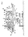
- the test device for vehicle wheel rims comprises a frame 1 consisting of a table 2, in the center of which is a column 3 provided at its base with a base 4, which is supported by adjustable feet 5.
- a rocket 6 is positioned carrying at its upper end a wheel 7 mounted by its hub 8 on bearings 9; the lower end of the rocket 6 carries a first gear 10 driven in rotation by means of a second gear 11 mounted on an electric motor 12.
- This device allows the rocket 6 to be driven in a rotational movement so as to carry out mechanical tests, more particularly of fatigue on the inner rings of the bearings 9, and of bending of the rocket 6.
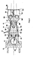
- supports 13 are arranged at regular angular intervals, and are each provided with two jacks 14 and 15, positioned one below the other, and diverging with respect to the supports 13 so that the upper cylinders 14 apply forces to the outer face, relative to the hub 8, of the upper flange 16 of the rim 18, and in that the lower cylinders 15 apply forces to the outer face, by relative to the hub 8, of the lower flange 17 of this same rim 18.
- each of the upper and lower cylinders 14 and 15 of the supports 13 are provided with a flexible shoe 19 of variable rigidity on which is fixed a distribution mattress, produced in the form of a rubber band 20 conforming to the shape of the flanges 16 and 17 of the rim 18; this shoe assembly 19 and distribution mattress 20 exactly matching the shape of the tire beads, the use of the latter is therefore no longer useful in this type of device.
- Each support 13 is connected to these two jacks 14 and 15 by means of two pads 21 and 22 slidably mounted in the support 13, and positioned one below the other; each of these pads 21 and 22 being connected to its respective jack by a rigid sole 23 adjustable in position on a concave face 24 presented by each pad, the pads being arranged so that their concave faces 24 are back-to-back , so as to allow an angular adjustment of the jacks 14 and 15 with respect to the wheel 7.
- each support 13 is adjusted vertically, or longitudinally, relative to the axis of the wheel, at by means of a screw 25 which is housed in a tapped hole made over the entire length of the two pads, and having two screw threads inverted so that the manipulation of the screw 25, in one direction or the other, spreads or brings the pads 21 and 22 closer to each other.
- a threaded rod 26 is provided which is housed in a threaded hole 27 belonging to the supports 13, and provided at its other end with a crank 28, the non-threaded part of the rod 26 being held in a lateral flange 29, fixed on table 2, and acting as a bearing.
- each support 13 there is mounted, on each support 13, a housing 53 inside which is held one end of a shaft 54, retained in translation by an external radial shoulder.
- a shoe 55 On the other end of each shaft 54, is fixed a shoe 55 to variable stiffness, provided with a rubber band 20, applying a force to the central part of the rim 18 by means of elastic elements such as "Belleville” type washers 56 mounted in the housing 53 around the shaft 54 .
- the cylinder 30 is supplied with hydraulic pressure by means of a hose 31; inside the cylinder 30 is mounted with sealing a piston 32 equipped with two seals 33 and 34.
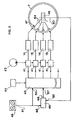
- This device comprises, in addition to the upper and lower cylinders 14 and 156, servo-valves 41 equal in number to the cylinders and controlling the latter.
- These servo-valves 41 are supplied by a hydraulic pump 42 and are controlled by a distributor 43.
- the latter is synchronized by receiving electrical pulses from a pulse generator of the clock type 44.
- the control input 60 of the distributor 43 is connected to the output 61 of a memory 48 into which has been introduced a set of information representative of a spectrum of stresses actually experienced by a wheel, in particular an aircraft, when the latter lands and rolls on the ground.
- This device is more particularly intended for testing aircraft wheels for their development.
- this device comprises a comparator 45 which receives on a first set of inputs 62 information coming from the output 63 of a transmitter 46 receiving on its inputs 64 signals emitted by strain gauges 47 distributed all around the wheel 7 and making it possible to determine the stresses actually applied to the wheel by the sets of jacks 14, 15.
- Comparator 45 also receives, on a second set of inputs 65, the same information as that supplied at output 61 of memory 48.
- the output 66 of the comparator 45 is connected to a second control input 67 of the distributor43.
- the test device for vehicle wheel rims described above with reference to FIGS. 1 to 4 works as follows.
- the mounting of the wheel 7 on its rocket 6, and the positions and adjustments of the jacks being carried out, the hydraulic pump 42 and the pulse generator of the clock type 44 are started, which has the consequence of supplying respectively the distributor 43 in electrical impulses and the servo-valves 41 in hydraulic fluid under pressure.
- the latter are controlled by the memory 48 and the distributor 43, and thus transmit to the jacks 14 and 15 a hydraulic control order of five cycles per second. Therefore, the lower and upper flanges 16 and 17 of the rim 18 will be subjected to stresses which will be similar to those received when the aircraft is taxiing on the ground and transmitted by the beads of the tire.
- the plurality of jacks 14 and 15 distributed regularly around the wheel 7 are controlled so that each pair of jacks 14 and 15, located one below the other, applies a force equal to that recorded by a wheel when it rolls on the ground; therefore, the stresses that the wheel 7 undergoes in being in the static position are equivalent to those that actually undergoes an identical wheel in being in the dynamic position, that is to say rolling.
- a first pair of jacks 14 and 15 applies a force F 1 (fig.
- gauges 47 thus record the stresses undergone by the wheel, which are then analyzed in the comparator 45, so as to possibly correct the signals emitted by the distributor 43 following the comparison between the device spectrum of the stresses established in the transmitter 46 and coming from wheel 7, and the real spectrum of stresses recorded on magnetic tapes in memory 48, and previously collected on a wheel in service.
- the value of the force of a jack does not correspond to the value programmed in the memory representing the real spectrum of the stresses.
- This error can come from a loss or leak of the electronic or hydraulic circuits.
- a jack is not sufficiently supplied, it produces a force which is less than that which should be applied to the rim.
- the corresponding gauge or gauges 47 will detect this lack and then produce a signal via the transmitter 46 to warn the comparator 45 on these inputs 62 of this fault.
- this comparator As on the other inputs 65 of this comparator 45, it receives the true values of the force which should be applied, this comparator then delivers at its output 66 an error signal (difference between the two forces) which, via the distributor 43 will control a greater supply of the jack to compensate for its loss of power .
- This operation would then be strictly identical in the case of an overpower, the error signal allowing a reduction in the supply of the jack so that it gives its true power.
- the error signal at the output of the comparator 45 will be zero and will not cause any correction of the signals coming from the memory 48.
- the memory 48 will be constituted by a magnetic strip which will also be synchronized for example from the clock 44 or from any other source of reference.
- the distributor will itself be constituted by a set, for example of flip-flops in number corresponding to that of the set of jacks, with which will be associated amplifiers controllable by the signals emitted by the comparator 45.
Landscapes
- General Health & Medical Sciences (AREA)
- Health & Medical Sciences (AREA)
- Life Sciences & Earth Sciences (AREA)
- Chemical & Material Sciences (AREA)
- Analytical Chemistry (AREA)
- Biochemistry (AREA)
- Physics & Mathematics (AREA)
- General Physics & Mathematics (AREA)
- Immunology (AREA)
- Pathology (AREA)
- Testing Of Balance (AREA)
- Tires In General (AREA)
- Force Measurement Appropriate To Specific Purposes (AREA)
Claims (16)
Applications Claiming Priority (2)
| Application Number | Priority Date | Filing Date | Title |
|---|---|---|---|
| FR7931093A FR2472181A1 (fr) | 1979-12-19 | 1979-12-19 | Machine de simulation d'essais pour roues de vehicules |
| FR7931093 | 1979-12-19 |
Publications (3)
| Publication Number | Publication Date |
|---|---|
| EP0031748A1 EP0031748A1 (de) | 1981-07-08 |
| EP0031748B1 EP0031748B1 (de) | 1984-04-11 |
| EP0031748B2 true EP0031748B2 (de) | 1989-01-18 |
Family
ID=9232940
Family Applications (1)
| Application Number | Title | Priority Date | Filing Date |
|---|---|---|---|
| EP80401772A Expired EP0031748B2 (de) | 1979-12-19 | 1980-12-10 | Verfahren und Vorrichtung zum Prüfen von Fahrzeugrädern |
Country Status (6)
| Country | Link |
|---|---|
| US (1) | US4375766A (de) |
| EP (1) | EP0031748B2 (de) |
| JP (1) | JPS5694236A (de) |
| CA (1) | CA1155681A (de) |
| DE (1) | DE3067487D1 (de) |
| FR (1) | FR2472181A1 (de) |
Families Citing this family (9)
| Publication number | Priority date | Publication date | Assignee | Title |
|---|---|---|---|---|
| DE19745671C1 (de) * | 1997-10-17 | 1999-05-06 | Porsche Ag | Verfahren und Vorrichtung zur thermoelastischen Spannungsanalyse an Fahrzeugrädern |
| US6901810B1 (en) * | 2002-08-08 | 2005-06-07 | Williams International Co. L.L.C. | Method of cyclic testing |
| DE102004021479A1 (de) * | 2004-04-30 | 2005-11-24 | Deutz Ag | Hydropulsvorrichtung |
| CN107167289A (zh) * | 2017-05-17 | 2017-09-15 | 上海应用技术大学 | 一种大悬臂预制拼装盖梁加载试验方法 |
| CN108918280B (zh) * | 2018-07-10 | 2021-04-20 | 中车长春轨道客车股份有限公司 | 车体端墙静强度试验加载装置 |
| CN111912704B (zh) * | 2020-07-16 | 2021-04-09 | 深圳市星恒通设备有限公司 | 一种新能源汽车轮胎静态试验测试系统及测试方法 |
| CN112485123B (zh) * | 2020-11-20 | 2022-11-04 | 长春众升科技发展有限公司 | 一种新能源汽车轮毂物性性能测试系统及测试方法 |
| CN114088565B (zh) * | 2021-10-28 | 2023-12-05 | 盐城工学院 | 一种工程实心轮胎耐磨性能测试台架 |
| CN114162345B (zh) * | 2021-11-25 | 2023-09-08 | 贵州安飞精密制造有限公司 | 一种旋翼桨毂轴颈测试系统及方法 |
Family Cites Families (5)
| Publication number | Priority date | Publication date | Assignee | Title |
|---|---|---|---|---|
| US3015949A (en) * | 1959-01-30 | 1962-01-09 | Western Electric Co | Method of and apparatus for vibration testing |
| US3559468A (en) * | 1968-07-12 | 1971-02-02 | Kelsey Hayes Co | Method and apparatus for rim fatigue and testing device |
| GB1438200A (de) * | 1973-12-17 | 1976-06-03 | ||
| DE2827728C2 (de) * | 1978-06-22 | 1984-04-05 | Mannesmann Kronprinz Ag, 5650 Solingen | Vorrichtung zum Prüfen der Dauerfestigkeit von Fahrzeugrädern |
| DE2854803B1 (de) * | 1978-12-15 | 1980-01-17 | Kronprinz Mannesmann | Vorrichtung und Verfahren zum Pruefen der Dauerfestigkeit von Fahrzeugraedern |
-
1979
- 1979-12-19 FR FR7931093A patent/FR2472181A1/fr active Granted
-
1980
- 1980-11-06 US US06/204,593 patent/US4375766A/en not_active Expired - Lifetime
- 1980-12-05 JP JP17109280A patent/JPS5694236A/ja active Pending
- 1980-12-05 CA CA000366271A patent/CA1155681A/fr not_active Expired
- 1980-12-10 EP EP80401772A patent/EP0031748B2/de not_active Expired
- 1980-12-10 DE DE8080401772T patent/DE3067487D1/de not_active Expired
Also Published As
| Publication number | Publication date |
|---|---|
| EP0031748B1 (de) | 1984-04-11 |
| US4375766A (en) | 1983-03-08 |
| FR2472181B1 (de) | 1983-04-08 |
| EP0031748A1 (de) | 1981-07-08 |
| CA1155681A (fr) | 1983-10-25 |
| FR2472181A1 (fr) | 1981-06-26 |
| DE3067487D1 (en) | 1984-05-17 |
| JPS5694236A (en) | 1981-07-30 |
Similar Documents
| Publication | Publication Date | Title |
|---|---|---|
| EP0031748B2 (de) | Verfahren und Vorrichtung zum Prüfen von Fahrzeugrädern | |
| US3724137A (en) | Means for correcting non-uniformity in tires | |
| US3914907A (en) | Method for improving the ride characteristics of tires | |
| WO2008025922A2 (fr) | Procede et dispositif d'etablissement et de controle d'un serrage hydraulique d'un ou de plusieurs boulons | |
| JP4904260B2 (ja) | 多軸ホイール疲労システムのための制御方法 | |
| CA2016472A1 (en) | Method and apparatus for detecting defects in pneumatic tire | |
| FR2625308A1 (fr) | Procede non destructif de detection de defauts dans un pneumatique | |
| FR2500420A1 (fr) | Chariot tracteur destine a se deplacer a l'interieur d'un tube | |
| CA2907602A1 (fr) | Procede de surveillance des deformations d'un element tournant par un dispositif de surveillance a fibre optique, et eolienne munie d'un tel dispositif | |
| FR3113381A1 (fr) | Installation et Procédé de Préparation et d’Encollage des Dispositifs de Fixation des Organes Electroniques aux Enveloppes des Pneumatiques | |
| US20200049593A1 (en) | Tire testing machine, method for testing a tire and computer program | |
| EP0156730A1 (de) | Einrichtung für geometrische Fehlerausgleichung für einen ringförmigen radialen Detektor bei einer elektromagnetischen Aufhängung eines Rotors | |
| EP1354183A1 (de) | Verfahren zur vorhersage des komfortgrades eines fahrzeuges | |
| JP3602805B2 (ja) | タイヤ組立体の馴染み加工装置 | |
| GB1433569A (en) | Method and apparatus for testing tyres | |
| FR2713771A1 (fr) | Procédé, dispositif et application pour l'équilibrage dynamique d'une pièce tournante en rotation. | |
| WO2003019130A1 (fr) | Machine et procede de controle d'une enveloppe | |
| FR2476310A1 (fr) | Dispositif pour centrer les roues a rayons, et procede pour la mise en oeuvre de ce dispositif | |
| EP4484917A3 (de) | Verfahren zum testen eines reifens | |
| FR2926972A1 (fr) | Appareil de diagnostic precoce du syndrome du canal carpien et procede et dispositif d'acquisition de l'information relative a la sensibilite cutanee du doigt du patient | |
| EP0345633A3 (de) | Vorrichtung zum Anbringen eines Elastomer-Füllers auf den Wulstkern eines Luftreifens | |
| FR2463640A3 (fr) | Dispositif de reglage de l'espace de dechargement d'un concasseur a cone fonctionnant par inertie | |
| EP0767366A1 (de) | Rotierender Spindelantrieb mit Schnellspannvorrichtung und Maschine damit | |
| US4211109A (en) | Multiple plane road wheel for use with tire measuring and correcting apparatus | |
| AU2239100A (en) | A method and appratus for testing tires |
Legal Events
| Date | Code | Title | Description |
|---|---|---|---|
| PUAI | Public reference made under article 153(3) epc to a published international application that has entered the european phase |
Free format text: ORIGINAL CODE: 0009012 |
|
| AK | Designated contracting states |
Designated state(s): DE FR GB IT |
|
| 17P | Request for examination filed |
Effective date: 19810706 |
|
| ITF | It: translation for a ep patent filed | ||
| GRAA | (expected) grant |
Free format text: ORIGINAL CODE: 0009210 |
|
| AK | Designated contracting states |
Designated state(s): DE FR GB IT |
|
| REF | Corresponds to: |
Ref document number: 3067487 Country of ref document: DE Date of ref document: 19840517 |
|
| PLBI | Opposition filed |
Free format text: ORIGINAL CODE: 0009260 |
|
| PGFP | Annual fee paid to national office [announced via postgrant information from national office to epo] |
Ref country code: FR Payment date: 19841227 Year of fee payment: 5 |
|
| 26 | Opposition filed |
Opponent name: GEBR. HOFMANN GMBH & CO. KG MASCHINENFABRIK Effective date: 19841207 |
|
| PLAB | Opposition data, opponent's data or that of the opponent's representative modified |
Free format text: ORIGINAL CODE: 0009299OPPO |
|
| R26 | Opposition filed (corrected) |
Opponent name: RESOPAL WERK H. ROEMMLER GMBH Effective date: 19841207 |
|
| PLAB | Opposition data, opponent's data or that of the opponent's representative modified |
Free format text: ORIGINAL CODE: 0009299OPPO |
|
| R26 | Opposition filed (corrected) |
Opponent name: RESOPAL WERK H. ROEMMLER GMBH Effective date: 19841207 |
|
| PLAB | Opposition data, opponent's data or that of the opponent's representative modified |
Free format text: ORIGINAL CODE: 0009299OPPO |
|
| R26 | Opposition filed (corrected) |
Opponent name: GEBR. HOFMANN GMBH & CO. KG MASCHINENFABRIK Effective date: 19841207 |
|
| ITF | It: translation for a ep patent filed | ||
| PUAH | Patent maintained in amended form |
Free format text: ORIGINAL CODE: 0009272 |
|
| STAA | Information on the status of an ep patent application or granted ep patent |
Free format text: STATUS: PATENT MAINTAINED AS AMENDED |
|
| PG25 | Lapsed in a contracting state [announced via postgrant information from national office to epo] |
Ref country code: GB Effective date: 19881210 |
|
| PGFP | Annual fee paid to national office [announced via postgrant information from national office to epo] |
Ref country code: DE Payment date: 19881221 Year of fee payment: 9 |
|
| 27A | Patent maintained in amended form |
Effective date: 19890118 |
|
| AK | Designated contracting states |
Kind code of ref document: B2 Designated state(s): DE FR GB IT |
|
| GBPC | Gb: european patent ceased through non-payment of renewal fee | ||
| PG25 | Lapsed in a contracting state [announced via postgrant information from national office to epo] |
Ref country code: FR Free format text: LAPSE BECAUSE OF NON-PAYMENT OF DUE FEES Effective date: 19890831 |
|
| REG | Reference to a national code |
Ref country code: FR Ref legal event code: ST |
|
| PG25 | Lapsed in a contracting state [announced via postgrant information from national office to epo] |
Ref country code: DE Effective date: 19900901 |
|
| APAH | Appeal reference modified |
Free format text: ORIGINAL CODE: EPIDOSCREFNO |