EP0031558B1 - Müllverbrennungsanlage - Google Patents
Müllverbrennungsanlage Download PDFInfo
- Publication number
- EP0031558B1 EP0031558B1 EP80108044A EP80108044A EP0031558B1 EP 0031558 B1 EP0031558 B1 EP 0031558B1 EP 80108044 A EP80108044 A EP 80108044A EP 80108044 A EP80108044 A EP 80108044A EP 0031558 B1 EP0031558 B1 EP 0031558B1
- Authority
- EP
- European Patent Office
- Prior art keywords
- refuse
- burner
- incineration plant
- plant according
- refuse incineration
- Prior art date
- Legal status (The legal status is an assumption and is not a legal conclusion. Google has not performed a legal analysis and makes no representation as to the accuracy of the status listed.)
- Expired
Links
- 239000002893 slag Substances 0.000 claims description 22
- 238000002485 combustion reaction Methods 0.000 claims description 21
- QVGXLLKOCUKJST-UHFFFAOYSA-N atomic oxygen Chemical compound [O] QVGXLLKOCUKJST-UHFFFAOYSA-N 0.000 claims description 11
- 238000001035 drying Methods 0.000 claims description 11
- 239000003546 flue gas Substances 0.000 claims description 11
- 239000007789 gas Substances 0.000 claims description 11
- 239000001301 oxygen Substances 0.000 claims description 11
- 229910052760 oxygen Inorganic materials 0.000 claims description 11
- 238000001816 cooling Methods 0.000 claims description 9
- UGFAIRIUMAVXCW-UHFFFAOYSA-N Carbon monoxide Chemical compound [O+]#[C-] UGFAIRIUMAVXCW-UHFFFAOYSA-N 0.000 claims description 6
- 238000004064 recycling Methods 0.000 claims description 3
- 238000010276 construction Methods 0.000 claims 1
- 238000007872 degassing Methods 0.000 claims 1
- 239000002699 waste material Substances 0.000 description 29
- 238000004056 waste incineration Methods 0.000 description 11
- 239000007788 liquid Substances 0.000 description 9
- XLYOFNOQVPJJNP-UHFFFAOYSA-N water Substances O XLYOFNOQVPJJNP-UHFFFAOYSA-N 0.000 description 6
- 239000000446 fuel Substances 0.000 description 5
- 239000000654 additive Substances 0.000 description 4
- 238000010438 heat treatment Methods 0.000 description 3
- 238000000197 pyrolysis Methods 0.000 description 3
- 239000000126 substance Substances 0.000 description 3
- 230000007717 exclusion Effects 0.000 description 2
- 239000011490 mineral wool Substances 0.000 description 2
- 239000000047 product Substances 0.000 description 2
- 239000000779 smoke Substances 0.000 description 2
- 239000013589 supplement Substances 0.000 description 2
- MYMOFIZGZYHOMD-UHFFFAOYSA-N Dioxygen Chemical compound O=O MYMOFIZGZYHOMD-UHFFFAOYSA-N 0.000 description 1
- 238000009825 accumulation Methods 0.000 description 1
- 230000006978 adaptation Effects 0.000 description 1
- 238000005273 aeration Methods 0.000 description 1
- 238000003763 carbonization Methods 0.000 description 1
- 239000000969 carrier Substances 0.000 description 1
- 238000006243 chemical reaction Methods 0.000 description 1
- 238000010924 continuous production Methods 0.000 description 1
- 231100000317 environmental toxin Toxicity 0.000 description 1
- 238000001704 evaporation Methods 0.000 description 1
- 230000008020 evaporation Effects 0.000 description 1
- 239000000284 extract Substances 0.000 description 1
- 238000011049 filling Methods 0.000 description 1
- 239000012530 fluid Substances 0.000 description 1
- 239000002803 fossil fuel Substances 0.000 description 1
- 238000000227 grinding Methods 0.000 description 1
- 239000000463 material Substances 0.000 description 1
- 238000000034 method Methods 0.000 description 1
- 239000000203 mixture Substances 0.000 description 1
- 239000010850 non-combustible waste Substances 0.000 description 1
- 238000013021 overheating Methods 0.000 description 1
- 239000003507 refrigerant Substances 0.000 description 1
- 238000005057 refrigeration Methods 0.000 description 1
- 239000002351 wastewater Substances 0.000 description 1
Images
Classifications
-
- F—MECHANICAL ENGINEERING; LIGHTING; HEATING; WEAPONS; BLASTING
- F23—COMBUSTION APPARATUS; COMBUSTION PROCESSES
- F23G—CREMATION FURNACES; CONSUMING WASTE PRODUCTS BY COMBUSTION
- F23G5/00—Incineration of waste; Incinerator constructions; Details, accessories or control therefor
- F23G5/08—Incineration of waste; Incinerator constructions; Details, accessories or control therefor having supplementary heating
- F23G5/085—High-temperature heating means, e.g. plasma, for partly melting the waste
-
- C—CHEMISTRY; METALLURGY
- C02—TREATMENT OF WATER, WASTE WATER, SEWAGE, OR SLUDGE
- C02F—TREATMENT OF WATER, WASTE WATER, SEWAGE, OR SLUDGE
- C02F11/00—Treatment of sludge; Devices therefor
- C02F11/06—Treatment of sludge; Devices therefor by oxidation
-
- C—CHEMISTRY; METALLURGY
- C02—TREATMENT OF WATER, WASTE WATER, SEWAGE, OR SLUDGE
- C02F—TREATMENT OF WATER, WASTE WATER, SEWAGE, OR SLUDGE
- C02F11/00—Treatment of sludge; Devices therefor
- C02F11/12—Treatment of sludge; Devices therefor by de-watering, drying or thickening
- C02F11/13—Treatment of sludge; Devices therefor by de-watering, drying or thickening by heating
-
- F—MECHANICAL ENGINEERING; LIGHTING; HEATING; WEAPONS; BLASTING
- F23—COMBUSTION APPARATUS; COMBUSTION PROCESSES
- F23G—CREMATION FURNACES; CONSUMING WASTE PRODUCTS BY COMBUSTION
- F23G5/00—Incineration of waste; Incinerator constructions; Details, accessories or control therefor
- F23G5/02—Incineration of waste; Incinerator constructions; Details, accessories or control therefor with pretreatment
- F23G5/04—Incineration of waste; Incinerator constructions; Details, accessories or control therefor with pretreatment drying
-
- F—MECHANICAL ENGINEERING; LIGHTING; HEATING; WEAPONS; BLASTING
- F23—COMBUSTION APPARATUS; COMBUSTION PROCESSES
- F23G—CREMATION FURNACES; CONSUMING WASTE PRODUCTS BY COMBUSTION
- F23G5/00—Incineration of waste; Incinerator constructions; Details, accessories or control therefor
- F23G5/44—Details; Accessories
- F23G5/46—Recuperation of heat
-
- F—MECHANICAL ENGINEERING; LIGHTING; HEATING; WEAPONS; BLASTING
- F23—COMBUSTION APPARATUS; COMBUSTION PROCESSES
- F23G—CREMATION FURNACES; CONSUMING WASTE PRODUCTS BY COMBUSTION
- F23G7/00—Incinerators or other apparatus for consuming industrial waste, e.g. chemicals
- F23G7/001—Incinerators or other apparatus for consuming industrial waste, e.g. chemicals for sludges or waste products from water treatment installations
-
- F—MECHANICAL ENGINEERING; LIGHTING; HEATING; WEAPONS; BLASTING
- F23—COMBUSTION APPARATUS; COMBUSTION PROCESSES
- F23G—CREMATION FURNACES; CONSUMING WASTE PRODUCTS BY COMBUSTION
- F23G2201/00—Pretreatment
- F23G2201/10—Drying by heat
- F23G2201/101—Drying by heat using indirect heat transfer
-
- F—MECHANICAL ENGINEERING; LIGHTING; HEATING; WEAPONS; BLASTING
- F23—COMBUSTION APPARATUS; COMBUSTION PROCESSES
- F23G—CREMATION FURNACES; CONSUMING WASTE PRODUCTS BY COMBUSTION
- F23G2201/00—Pretreatment
- F23G2201/70—Blending
-
- F—MECHANICAL ENGINEERING; LIGHTING; HEATING; WEAPONS; BLASTING
- F23—COMBUSTION APPARATUS; COMBUSTION PROCESSES
- F23G—CREMATION FURNACES; CONSUMING WASTE PRODUCTS BY COMBUSTION
- F23G2201/00—Pretreatment
- F23G2201/80—Shredding
-
- F—MECHANICAL ENGINEERING; LIGHTING; HEATING; WEAPONS; BLASTING
- F23—COMBUSTION APPARATUS; COMBUSTION PROCESSES
- F23G—CREMATION FURNACES; CONSUMING WASTE PRODUCTS BY COMBUSTION
- F23G2201/00—Pretreatment
- F23G2201/90—Cooling
-
- F—MECHANICAL ENGINEERING; LIGHTING; HEATING; WEAPONS; BLASTING
- F23—COMBUSTION APPARATUS; COMBUSTION PROCESSES
- F23G—CREMATION FURNACES; CONSUMING WASTE PRODUCTS BY COMBUSTION
- F23G2202/00—Combustion
- F23G2202/20—Combustion to temperatures melting waste
-
- F—MECHANICAL ENGINEERING; LIGHTING; HEATING; WEAPONS; BLASTING
- F23—COMBUSTION APPARATUS; COMBUSTION PROCESSES
- F23G—CREMATION FURNACES; CONSUMING WASTE PRODUCTS BY COMBUSTION
- F23G2206/00—Waste heat recuperation
- F23G2206/10—Waste heat recuperation reintroducing the heat in the same process, e.g. for predrying
-
- F—MECHANICAL ENGINEERING; LIGHTING; HEATING; WEAPONS; BLASTING
- F23—COMBUSTION APPARATUS; COMBUSTION PROCESSES
- F23L—SUPPLYING AIR OR NON-COMBUSTIBLE LIQUIDS OR GASES TO COMBUSTION APPARATUS IN GENERAL ; VALVES OR DAMPERS SPECIALLY ADAPTED FOR CONTROLLING AIR SUPPLY OR DRAUGHT IN COMBUSTION APPARATUS; INDUCING DRAUGHT IN COMBUSTION APPARATUS; TOPS FOR CHIMNEYS OR VENTILATING SHAFTS; TERMINALS FOR FLUES
- F23L2900/00—Special arrangements for supplying or treating air or oxidant for combustion; Injecting inert gas, water or steam into the combustion chamber
- F23L2900/07005—Injecting pure oxygen or oxygen enriched air
-
- Y—GENERAL TAGGING OF NEW TECHNOLOGICAL DEVELOPMENTS; GENERAL TAGGING OF CROSS-SECTIONAL TECHNOLOGIES SPANNING OVER SEVERAL SECTIONS OF THE IPC; TECHNICAL SUBJECTS COVERED BY FORMER USPC CROSS-REFERENCE ART COLLECTIONS [XRACs] AND DIGESTS
- Y02—TECHNOLOGIES OR APPLICATIONS FOR MITIGATION OR ADAPTATION AGAINST CLIMATE CHANGE
- Y02E—REDUCTION OF GREENHOUSE GAS [GHG] EMISSIONS, RELATED TO ENERGY GENERATION, TRANSMISSION OR DISTRIBUTION
- Y02E20/00—Combustion technologies with mitigation potential
- Y02E20/34—Indirect CO2mitigation, i.e. by acting on non CO2directly related matters of the process, e.g. pre-heating or heat recovery
-
- Y—GENERAL TAGGING OF NEW TECHNOLOGICAL DEVELOPMENTS; GENERAL TAGGING OF CROSS-SECTIONAL TECHNOLOGIES SPANNING OVER SEVERAL SECTIONS OF THE IPC; TECHNICAL SUBJECTS COVERED BY FORMER USPC CROSS-REFERENCE ART COLLECTIONS [XRACs] AND DIGESTS
- Y02—TECHNOLOGIES OR APPLICATIONS FOR MITIGATION OR ADAPTATION AGAINST CLIMATE CHANGE
- Y02W—CLIMATE CHANGE MITIGATION TECHNOLOGIES RELATED TO WASTEWATER TREATMENT OR WASTE MANAGEMENT
- Y02W10/00—Technologies for wastewater treatment
- Y02W10/30—Wastewater or sewage treatment systems using renewable energies
- Y02W10/37—Wastewater or sewage treatment systems using renewable energies using solar energy
-
- Y—GENERAL TAGGING OF NEW TECHNOLOGICAL DEVELOPMENTS; GENERAL TAGGING OF CROSS-SECTIONAL TECHNOLOGIES SPANNING OVER SEVERAL SECTIONS OF THE IPC; TECHNICAL SUBJECTS COVERED BY FORMER USPC CROSS-REFERENCE ART COLLECTIONS [XRACs] AND DIGESTS
- Y02—TECHNOLOGIES OR APPLICATIONS FOR MITIGATION OR ADAPTATION AGAINST CLIMATE CHANGE
- Y02W—CLIMATE CHANGE MITIGATION TECHNOLOGIES RELATED TO WASTEWATER TREATMENT OR WASTE MANAGEMENT
- Y02W10/00—Technologies for wastewater treatment
- Y02W10/40—Valorisation of by-products of wastewater, sewage or sludge processing
Definitions
- the invention relates to a waste incineration plant with recirculation of the energy.
- the invention has for its object to provide a waste incineration plant in which a complete combustion of the waste is achieved and the non-combustible components can be safely converted into liquid slag.
- the energy generated is returned via a heat exchanger and a drying stage of the raw waste.
- the heat exchanger can lead to the operation of a turbine with which a compressor for conveying heated air is operated.
- a chiller can also be driven when it comes to making pre-dried waste odor-free and therefore more storable.
- the liquid slag produced in the slag bath is drained off if necessary.
- Supplements can be added to the slag bath to supplement or promote liquefaction.
- the liquefied non-combustible waste residues thus liquefied can be processed directly into blast furnace slag-like products, such as grit, paving stones, foamed slag or slag wool, after they have been discharged from the tray burner, which is the subject of EP-A-0 097 976 (application 83 107 173.3).
- the garbage is transported preferably via pipes or channels with the aid of tappets or screw conveyors which separate the system from the outside air and act as a backflow filter when the garbage is compressed and enable the addition of gaseous or liquid additional fuels such as waste oil. If, for example, a drum with an external screw is used to dry the waste, loosened waste can serve as an adhesion filter for the flue gases to be removed.
- waste oil in the area of the bowl burner is not only advantageous because of the energy balance, but also because of the environmental toxins in the waste oil, which, if they do not burn, are absorbed and bound by the slag.
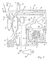
- the plant for the recycling of waste shown schematically in FIG. 1 enables the continuous conversion of raw waste into usable heat energy and usable slag.
- the raw waste 1 fed into a hopper 10 from above is moved by a feed tappet 11 (or a screw conveyor) through a tubular predrying duct 14 of a predrying stage 13 and at the end of the predrying duct falls from above into a double-walled cooling drying container 21 of a cooling drying stage 20.
- the predrying duct 14 is arranged inside a flue gas duct 16; the low-temperature energy of the waste incinerator is used.
- the used smoke gases 4 are then discharged through a chimney 17.
- the pre-dried waste located in the interior of the cooling drying container 21 is cooled by a refrigerant which is located between an inner wall 22 and an outer wall 23 of the container 21 and is connected to a refrigerator 24 via lines.
- a negative pressure prevails in the interior of the cooling drying container 21, generated via a suction channel 28 which is connected to a suction container 27 to which a suction pump 29 is connected.
- the odorous substances 6 present in the waste are discharged via a discharge line 30.
- the dried and degassed waste from the cooling drying stage 20 can optionally be poured into a storage 34 or into a funnel 35 of a conveyor channel 36 leading to the waste incineration furnace via a switchable connection piece 32.
- a conveyor tappet 12 moves the dried waste 2 through the conveyor channel 36 into the waste incineration furnace, which in the device according to the invention is an annular cup burner 40 made of refractory stones.
- the burner forms the subject of EP-A-0097976 (application 83 107 173.3) and is described in more detail there.
- the delivery channel 36 opens vertically and from below into a mushroom-shaped burner head 41 with a conical outer surface 44 that slopes downwards and downwards.
- An oxygen channel 42 is connected to nozzles 43 for dispensing Oxygen into a combustion zone 52 arranged above the burner head 41.
- a slag bath 49 Between the mushroom-shaped burner head 41 and a cylindrical outer wall 46 of the cup burner 40, for example, there is a slag bath 49 to which a discharge channel 50 for liquid slag is connected.
- the outer wall 46 of the cup burner 40 has an inwardly bevelled upper side 46a, below which nozzles 47 open into the combustion chamber. Air 9, possibly enriched with oxygen, is thus released into the combustion zone 52.
- the cup burner 40 which is open at the top, is covered by a hood 53 which guides the flue gases 4 past a heat exchanger designed as an evaporator 54 to the flue gas duct 16 of the predrying stage 13.
- Steam generated in the evaporator 54 is conducted via steam lines 55, in which valves 56 are located, to the refrigeration machine 24 and into a turbine 57.
- Raw waste 1 with a relatively high water content is filled into the filling funnel 10 and moved through the predrying stage 13 with the aid of the pusher 11 and pre-dried therein by the flue gases 4.
- the pre-dried waste 2 falls into the container 21 of the cooling drying stage 20, in which there is negative pressure.
- odorous substances are extracted and discharged via the suction container 27, the suction pump 29 and the discharge line 30, and water vapor is deposited and separated.
- the pre-dried waste 2 is poured from the lower part of the cooling drying container 21 into a storage 34 or a funnel 35 of a further conveying channel 36 by means of a switchable connection piece 32, if necessary.
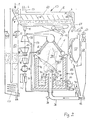
- the dried garbage 2 is continuously transported directly into the combustion zone 52 inside the cup burner 40 by a conveyor pusher 12 (or possibly a screw conveyor), where a garbage cone 73 (FIG. 2) forms on the mushroom-shaped burner head 41.
- a garbage cone 73 (FIG. 2) forms on the mushroom-shaped burner head 41.
- air, possibly oxygen-enriched air 9 emerges from the nozzles 43 of the burner head 41 and the nozzles 47 of the burner outer wall 46 into the combustion zone 52. It is about a very high combustion temperature between 1100 and about 1600 ° C, which can be achieved in an emergency by the oxygen supply.
- the particular shape of the cup burner favors the high temperature in the combustion zone because the heat reflects off the walls of the cup burner and the air supplied at 47 is heated and this heat is introduced into the combustion zone 52.
- the evaporator 54 arranged above it also radiates heat back. At the high combustion temperature generated, pyrolysis occurs in the waste cone above the burner head 41. Incombustible residues liquefy and flow into the slag bath 49 surrounding the burner head 41.
- additives can be added in order to achieve a fluid slag bath 49 and certain material properties which are valuable in products such as grit, paving stones, foamed slag or slag wool.
- liquid or gaseous fuel or additives such as waste oil to the dried waste 2, for example in the area of the conveying channel 36 via suitable inlet channels 37.
- the steam generated by the intensive waste incineration can be used in many ways, e.g. B. for the units of the system (the refrigerator 24, the turbine 57). There is also the possibility of using the steam generated in this way for heating purposes.
- the modified exemplary embodiment of the waste incineration plant shown in FIG. 2 partly has the same or similar devices as the exemplary embodiment shown in FIG. 1, which therefore bear the same reference numbers.
- the moist raw waste 1 passes through a gas-blocking hopper 10 into a rotary drum 60 provided with an external screw conveyor 61, which is located within the flue gas duct 16 of the cup burner 40 and is heated either indirectly or directly by the flue gases 4.
- a rotary drum 60 At the end of the rotary drum 60, the water contained in the raw waste 1 emerges as waste steam 5 and is optionally fed to a scrubber 62 or a condenser within an evaporation channel 63.
- the waste steam is directly condensed in the scrubber 62 and its heat is dissipated as district heating via a heat exchanger 64.
- the rotary drum 60 is heated externally (indirectly), the flue gases and waste water vapor remain separate and can be condensed or washed separately.
- the garbage either completely or partially dried in this way, leaves the rotary drum through a gas-blocking fill 65 and is optionally fed to a sorting stage 66 or a grinding stage 67.
- Ground and dry garbage is bunkered in a storage 68, semi-dry garbage in the cooling drying stage 20 already described in connection with FIG. 1 is freed of residual water by freeze-down drainage and then also bunkered via a storage inlet 68a.
- Drying and heating are carried out with a largely exclusion of oxygen and exclusion of outside air, so that any fire risk is avoided and the environment is not polluted.
- the garbage is conveyed together with additives 70 with the feed tappet 12 through the feed channel 36, optionally with the addition of liquid or gaseous fuel or additives, via the feed channels 37 from below via the riser pipe into the mushroom-shaped burner head 41 of the cup burner 40.
- On the conical surface 44 of the The burner head 41 forms the garbage a drain pan 73, from which liquid slag flows via the conical outer surface 44 of the burner head 41 into the liquid slag bath 49.
- the drain cone 73 lies in the core of the strongly reflecting hot cylindrical outer wall 46 of the cup burner 40.
- the air supply 90 for the burn-up is divided into two partial flows for a lower burn-off zone 71 and a lateral upper burn-off zone 72 at the upper end of the outer wall 46.
- This air cools the burner bowl on all sides and conducts practically all the heat emitted by the furnace concentrically back to the combustion cone.
- This preheated combustion air is guided tangentially obliquely downwards through nozzles 47 upon entry into the burner switch and tangentially orbits the outlet cone 73 in the burner bowl.
- a helical flame 74 forms and smoke gases exit the burner pot upwards.
- the burner flame 74 is constricted at the location of the upper fresh air nozzles 47, and an almost spherical combustion chamber with the highest heat accumulation is thus formed.
- a pyrolysis zone 75 of the fuel is formed under this heat backflow.
- the smoldering gases generated together with the evaporated residual water form with the supplied air a tangentially circulating high-temperature fluidized bed around the drain cone 73. Ash and slag are separated downwards and form the liquid slag bath 49, which is kept at the same level via the drain 50.
- pure oxygen or oxygen-enriched air from an aeration stage 76 is added to the partial air flow in the lower combustion zone 71 above the slag bath.
- Ash parts entrained with the flame 74 are discharged from the screw 74, which rotates upward when it quickly loses speed after constriction at the upper edge of the burner jacket, and is fed to the slag bath 49 via the conically shaped roof surface 46a at the edge of the burner wall 46.
- gas turbine 83 with a generator 84 which, by means of a compressor set 78 with intercooler 85, conducts air 80 through a heat exchanger 86 arranged in the combustion chamber of the shell burner 40 into a turbine 88, where it is expanded and then fed to the burner pot as preheated combustion air 90 .
- the gas turbine 83 also includes a compressor 92, which extracts low-temperature exhaust gases 4 from an exhaust gas receiver 93 located within the combustion chamber and compresses them as process heat carriers.
- the gas turbine 83 described above with its units can also be connected downstream of a steam air system or replaced by such.
Landscapes
- Engineering & Computer Science (AREA)
- Mechanical Engineering (AREA)
- General Engineering & Computer Science (AREA)
- Environmental & Geological Engineering (AREA)
- Water Supply & Treatment (AREA)
- Chemical & Material Sciences (AREA)
- Hydrology & Water Resources (AREA)
- Organic Chemistry (AREA)
- Life Sciences & Earth Sciences (AREA)
- Physics & Mathematics (AREA)
- Plasma & Fusion (AREA)
- Processing Of Solid Wastes (AREA)
- Gasification And Melting Of Waste (AREA)
Description
- Die Erfindung bezieht sich auf eine Müllverbrennungsanlage unter Rückführung der anfallenden Energie.
- Die Rückführung der anfallenden Energie in Müllverbrennungsanlagen ist an sich bekannt (DE-A-1 526 113). Dabei werden mindestens zwei Kessel angewendet, wovon der eine als Hochdruckkessel ausgebildet ist und mit fossilen Brennstoffen zur Überhitzung betrieben wird. Eine sonstige Anpassung an die Verbrennung von Müll ist nicht offenbart.
- Bei einer weiteren bekannten Müllverbrennungsanlage (US-A-3918374) sind hintereinandergeschaltete Öfen vorgesehen, die wenigstens teilweise zur Erzeugung von Schwelgas durch Pyrolyse ausgebildet sind und teilweise durch Sauerstoff betrieben werden. Die Verwendung von Sauerstoff für den Normalbetrieb ist ziemlich teuer.
- Gebaute Müllverbrennungsanlagen enthalten üblicherweise einen Rost oder Wanderrost, auf dem der Müll grossflächig verbrennt. Die Feuerraumtemperatur soll 1050°C nicht überschreiten, weil andernfalls die Schlackenbeseitigung erschwert wäre. Andererseits soll die Feuerraumtemperatur 900 °C nicht unterschreiten, weil sonst die restlose Verbrennung gefährdet wäre. Es wird deshalb etwa 950 °C eingehalten, was jedoch bei einem relativ grossen Feuerraum, wie bei einem Rost vorausgesetzt, schwierig ist, weil die Müllzusammensetzung schwankt.
- Der Erfindung liegt die Aufgabe zugrunde, eine Müllverbrennungsanlage zu schaffen, in welcher eine vollständige Verbrennung des Mülls erzielt und die nicht brennbaren Bestandteile sicher in flüssige Schlacke überführt werden können.
- Die Lösung dieser Aufgabe ergibt sich aus der Lehre des Anspruches 1.
- Die Rückführung der anfallenden Energie erfolgt dabei über einen Wärmetauscher und über eine Trocknungsstufe des Rohmulls. Der Wärmetauscher kann zum Betrieb einer Turbine führen, mit welcher ein Kompressor zur Förderung von erwärmter Luft betrieben wird. Es kann auch eine Kältemaschine angetrieben werden, wenn es darum geht, vorgetrockneten Müll geruchfrei und damit besser lagerfähig zu machen.
- Die im Schlackenbad anfallende flüssige Schlacke wird bei Bedarf abgeleitet. Zur Ergänzung oder zur Förderung der Verflüssigung können dem Schlackenbad Zuschläge zugesetzt werden. Die so verflüssigten unbrennbaren Müllrückstände können nach ihrer Ableitung aus dem Schalenbrenner, der den Gegenstand des EP-A-0 097 976 (Anmeldung 83 107 173.3) bildet, direkt zu hochofenschlackenartigen Produkten, wie Splitt, Pflastersteinen, geschäumter Schlacke oder Schlackenwolle verarbeitet werden.
- Innerhalb der Vorrichtung erfolgt der Mülltransport vorzugsweise über Rohre oder Kanäle mit Hilfe von Stösseln oder Förderschnecken, die das System von Aussenluft trennen und bei Verdichtung des Mülls als Rückstaufilter wirken und die Zugabe von gasförmigen oder flüssigen Zusatzbrennstoffen wie Altöl ermöglichen. Wird beispielsweise eine Trommel mit Aussenschnecke bei der Mülltrocknung verwendet, dann kann gelockerter Müll als Adhäsionsfilter der abzuführenden Rauchgase dienen.
- Die Möglichkeit des Zusetzens von Altöl im Bereich des Schalenbrenners ist nicht nur wegen der Energiebilanz vorteilhaft, sondern auch wegen der Umweltgifte im Altöl, die, soweit sie nicht verbrennen, von der Schlacke aufgenommen und gebunden werden.
- Nachstehend werden zwei Ausführungsbeispiele der Erfindung unter Bezugnahme auf die Zeichnung näher erläutert. Darin zeigen:
- Fig. 1 eine erste Müllverbrennungsanlage und
- Fig. 2 eine zweite Müllverbrennungsanlage.
- Die in Fig. 1 schematisch dargestellte Anlage zur Verwertung von Müll ermöglicht die fortlaufende Umwandlung von Rohmüll in verwertbare Wärmeenergie und verwertbare Schlacke. Der in einen Einfülltrichter 10 von oben her zugeführte Rohmüll 1 wird von einem Förderstössel 11 (oder einer Förderschnecke) durch einen rohrförmigen Vortrocknungskanal 14 einer Vortrocknungsstufe 13 bewegt und fällt am Ende des Vortrocknungskanals von oben her in einen doppelwandigen Kühltrocknungsbehälter 21 einer Kühltrocknungsstufe 20. Der Vortrocknungskanal 14 ist im Inneren einer Rauchgasführung 16 angeordnet; es wird also die Niedertemperatur-Energie des Müllverbrennungsofens verwertet. Die ausgenutzten Rauchgase 4 werden anschliessend durch eine Esse 17 abgeleitet.
- Der im Innern des Kühltrocknungsbehälters 21 befindliche, vorgetrocknete Müll wird durch ein Kältemittel gekühlt, welches sich zwischen einer Innenwand 22 und einer Aussenwand 23 des Behälters 21 befindet und über Leitungen mit einer Kältemaschine 24 in Verbindung steht. Im Innern des Kühltrocknungsbehälters 21 herrscht ein Unterdruck, erzeugt über einen Absaugkanal 28, der mit einem Absaugbehälter 27 verbunden ist, an den eine Saugpumpe 29 angeschlossen ist. Die im Müll vorhandenen Geruchsstoffe 6 werden über eine Abführleitung 30 abgeleitet.
- Über einen eine Weiche bildenden, umschaltbaren Stutzen 32 kann der getrocknete und entgaste Müll aus der Kühltrocknungsstufe 20 wahlweise in einen Speicher 34 oder in einen Trichter 35 eines zum Müllverbrennungsofen führende Förderkanals 36 geschüttet werden.
- Ein Förderstössel 12 bewegt den getrockneten Müll 2 durch den Förderkanal 36 in den Müllverbrennungsofen, der bei der erfindungsgemässen Vorrichtung ein aus feuerfesten Steinen hergestellter, ringförmiger Schalenbrenner 40 ist. Der Brenner bildet den Gegenstand des EP-A-0097976 (Anmeldung 83 107 173.3) und ist dort näher beschrieben.
- Der Förderkanal 36 mündet senkrecht und von unten her in einen pilzförmigen Brennerkopf 41 mit einer nach aussen und unten abfallenden konischen Mantelfläche 44. Ein Sauerstoffkanal 42 steht in Verbindung mit Düsen 43 zur Abgabe von Sauerstoff in eine über dem Brennerkopf 41 angeordnete Verbrennungszone 52. Zwischen dem pilzförmigen Brennerkopf 41 und einer beispielsweise zylindrischen Aussenwand 46 des Schalenbrenners 40 befindet sich ein Schlackenbad 49, an das ein Ableitungskanal 50 für flüssige Schlacke angeschlossen ist.
- Die Aussenwand 46 des Schalenbrenners 40 besitzt eine nach innen abgeschrägte Oberseite 46a, unterhalb welcher Düsen 47 in die Brennkammer einmünden. Damit wird Luft 9, gegebenenfalls mit Sauerstoff angereicherte, in die Verbrennungszone 52 abgegeben.
- Der oben offene Schalenbrenner 40 ist mit einer Haube 53 abgedeckt, welche die Rauchgase 4 an einem als Verdampfer 54 ausgebildeten Wärmetauscher vorbei zu der Rauchgasführung 16 der Vortrocknungsstufe 13 leitet.
- In dem Verdampfer 54 erzeugter Dampf wird über Dampfleitungen 55, in denen sich Ventile 56 befinden, zur Kältemaschine 24 und in eine Turbine 57 geleitet.
- Es wird Rohmüll 1 mit relativ hohem Wassergehalt, wie er gewöhnlich von kommunalen Müllabfuhrunternehmen angeliefert wird, in den Einfülltrichter 10 gefüllt und mit Hilfe des Förderstössels 11 durch die Vortrocknungsstufe 13 bewegt und darin durch die Rauchgase 4 vorgetrocknet. Der vorgetrocknete Müll 2 fällt in den Behälter 21 der Kühltrocknungsstufe 20, in welcher Unterdruck herrscht. Hierdurch werden Geruchsstoffe entzogen und über den Absaugbehälter 27, die Saugpumpe 29 und die Abführleitung 30 abgeleitet, sowie Wasserdampf niedergeschlagen und abgetrennt.
- Im Zuge des kontinuierlich ablaufenden Verfahrens wird der vorgetrocknete Müll 2 aus dem unteren Teil des Kühltrocknungsbehälters 21 mittels eines umschaltbaren Stutzens 32 bedarfsweise entweder in einen Speicher 34 oder einen Trichter 35 eines weiterführenden Förderkanals 36 geschüttet. In diesem wird der getrocknete Müll 2 durch einen Förderstössel 12 (oder gegebenenfalls eine Förderschnecke) kontinuierlich direkt in die Verbrennungszone 52 im Innern des Schalenbrenners 40 transportiert, wo sich auf dem pilzförmigen Brennerkopf 41 ein Müllkegel 73 (Fig.2) bildet. Falls erforderlich, tritt aus den Düsen 43 des Brennerkopfes 41 und den Düsen 47 der Brenneraussenwand 46 Luft, gegebenenfalls mit Sauerstoff angereicherte Luft 9 in die Verbrennungszone 52 aus. Es geht um eine sehr hohe Verbrennungstemperatur zwischen 1100 und etwa 1600 °C, die man im Notfall durch die Sauerstoffzufuhr erzielt. Die besondere Form des Schalenbrenners begünstigt die hohe Temperatur in der Verbrennungszone, weil die Wärme von den Wänden des Schalenbrenners rückstrahlt und die bei 47 zugeführte Luft aufgeheizt wird und diese Wärme in die Verbrennungszone 52 einträgt. Auch der darüber angeordnete Verdampfer 54 strahlt Wärme zurück. Bei der erzeugten hohen Verbrennungstemperatur tritt in dem Müllkegel oberhalb des Brennerkopfes 41 Pyrolyse auf. Unbrennbare Rückstände verflüssigen und fliessen in das den Brennerkopf 41 umgebende Schlackenbad 49 ab.
- Gegebenenfalls können Zuschlagstoffe zugesetzt werden, um ein leichtflüssiges Schlackenbad 49 und gewisse Materialeigenschaften zu erzielen, die bei Produkten, wie Splitt, Pflastersteine, geschäumte Schlacke oder Schlackenwolle, wertvoll sind.
- Es ist vorgesehen, dem getrockneten Müll 2 beispielsweise im Bereich des Förderkanals 36 über geeignete Einführkanäle 37 flüssige oder gasförmige Brenn- oder Zuschlagstoffe wie Altöl zuzusetzen. Darin enthaltene Stoffe gehen z.T. in die abgeleitete Schlacke.
- Der durch die intensive Müllverbrennung erzeugte Dampf kann vielfach ausgenutzt werden, z. B. für die Aggregate der Anlage (die Kältemaschine 24, die Turbine 57). Ferner besteht die Möglichkeit, den so erzeugten Dampf zu Heizzwecken heranzuziehen.
- Das in Fig. 2 dargestellte abgewandelte Ausführungsbeispiel der Müllverbrennungsanlage besitzt teilweise gleiche oder ähnliche Einrichtungen wie das in Fig. 1 dargestellte Ausführungsbeispiel, die daher die gleichen Bezugszahlen tragen.
- Der feuchte Rohmüll 1 gelangt über einen gassperrenden Einfülltrichter 10 in eine mit einer Aussenförderschnecke 61 versehenen Drehtrommel 60, die sich innerhalb der Rauchgasführung 16 des Schalenbrenners 40 befindet und durch die Rauchgase 4 entweder indirekt oder direkt beheizt wird. Am Ende der Drehtrommel 60 tritt das im Rohmüll 1 enthaltene Wasser als Abdampf 5 aus und wird innerhalb eines Abdampfungskanals 63 wahlweise einem Wäscher 62 oder einem Kondensator zugeführt.
- Im Wäscher 62 wird der Abdampf direkt kondensiert und seine Wärme über einen Wärmetauscher 64 als Fernwärme abgeführt. Bei der äusserlichen (indirekten) Beheizung der Drehtrommel 60 bleiben Rauchgase und Müll-Wasserdampf getrennt und können getrennt kondensiert bzw. gewaschen werden. Der so entweder ganz oder teilweise getrocknete Müll verlässt die Drehtrommel durch eine gassperrende Aufschüttung 65 und wird wahlweise einer Sortierstufe 66 oder einer Mahlstufe 67 zugeführt. Gemahlener und trockener Müll wird in einem Speicher 68 gebunkert, halbtrockener Müll in der bereits in Verbindung mit Fig. 1 beschriebenen Kühltrocknungsstufe 20 durch Unterdruckentwässerung mit Ausfrierung von Restwasser befreit und dann über einen Speichereinlass 68a ebenfalls gebunkert.
- Die Trocknung und Beheizung erfolgen unter weitgehendem Sauerstoffausschluss und Aussenluftabschluss, so dass jede Brandgefahr vermieden und die Umwelt nicht belastet wird.
- Vom Speicher 68 wird der Müll gegebenenfalls zusammen mit Zuschlagstoffen 70 mit dem Förderstössel 12 durch den Förderkanal 36, gegebenenfalls unter Zugabe flüssiger oder gasförmiger Brenn- oder Zuschlagstoffe, über die Einführkanäle 37 von unten über das Steigrohr in den pilzförmigen Brennerkopf 41 des Schalenbrenners 40 gefördert. Auf der konischen Mantelfläche 44 des Brennerkopfes 41 bildet der Müll einen Ablaufkeget 73, von dem flüssige Schlacke über die konische Mantelfläche 44 des Brennerkopfes 41 in das flüssige Schlackebad 49 abfliesst. Der Ablaufkegel 73 liegt im Kern der stark rückstrahlenden heissen zylindrischen Aussenwand 46 des Schalenbrenners 40. Die Luftzufuhr 90 für den Abbrand ist in zwei Teilströme für eine untere Abbrandzone 71 und eine seitliche obere Abbrandzone 72 am oberen Ende der Aussenwand 46 unterteilt. Diese Luft kühlt allseitig die Brennerschale und führt praktisch alle von der Feuerung abgehende Wärme konzentrisch wieder auf den Abbrandkegel zurück. Diese vorgewärmte Verbrennungsluft wird beim Eintritt in die Brennerschalte durch Düsen 47 tangential schräg nach unten geführt und umkreist in der Brennerschale den Ablaufkegel 73 tangential. Es bildet sich eine schraubenförmige Flamme 74, und Rauchgase verlassen den Brennertopf nach oben. Hierbei wird die Brennerflamme 74 an der Stelle der oberen Frischluftdüsen 47 eingeschnürt und so ein fast kugelförmiger Brennraum mit höchstem Wärmerückstau gebildet.
- Im Kern des Müll-Ablaufkegels 73 bildet sich unter diesem Wärmerückstau eine Pyrolysezone 75 des Brennmaterials. Die erzeugten Schwelgase zusammen mit dem verdampften Restwasser bilden mit der zugeführten Luft ein tangential kreisendes Hochtemperaturwirbelbett um den Ablaufkegel 73. Asche und Schlacke werden hierbei nach unten aussen abgeschieden und bilden das flüssige Schlackebad 49, das über den Ablauf 50 auf gleichem Niveau gehalten wird.
- Um die Temperatur im Schlackebad 49 hoch genug zu halten, wird in den Luft-Teilstrom der unteren Abbrandzone 71 über dem Schlackebad je nach Brennmaterial gegebenenfalls reiner Sauerstoff oder mit Sauerstoff angereicherte Luft aus einer Belüftungsstufe 76 zugesetzt.
- Mit der Flamme 74 mitgerissene Aschenteile werden aus der sich schraubenförmig nach oben drehenden Flamme 74 ausgeschieden, wenn sie nach der Einschnürung am oberen Brennermantelrand schnell an Geschwindigkeit verliert, und über die konisch ausgebildete Dachfläche 46a am Rand der Brennerwand 46 dem Schlackebad 49 zugeführt.
- Ferner ist eine Gasturbine 83 mit einem Generator 84 vorhanden, die mittels eines Verdichtersatzes 78 mit Zwischenkühler 85 Luft 80 durch einen im Brennraum des Schalenbrenners 40 angeordneten Wärmetauscher 86 in eine Turbine 88 leitet, wo sie entspannt und anschliessend dem Brennertopf als vorgewärmte Brennluft 90 zugeführt wird. Ferner gehört zu der Gasturbine 83 ein Verdichter 92, der an einem innerhalb des Brennraumes gelegenen Abgasaufnehmer 93 Niedertemperaturabgase 4 entnimmt und als Prozesswärmeträger verdichtet.
- Die zuvor beschriebene Gasturbine 83 mit ihren Aggregaten kann auch einer Dampf-Luftanlage nachgeschaltet oder durch eine solche ersetzt werden.
Claims (10)
Priority Applications (3)
| Application Number | Priority Date | Filing Date | Title |
|---|---|---|---|
| AT83107173T ATE17034T1 (de) | 1979-12-21 | 1980-12-19 | Brenner, insbesondere zur verbrennung von muell in muellverbrennungsanlagen. |
| AT80108044T ATE17033T1 (de) | 1979-12-21 | 1980-12-19 | Muellverbrennungsanlage. |
| DE8383107173T DE3071305D1 (en) | 1979-12-21 | 1980-12-19 | Burner, especially for the combustion of refuse in incineration plants |
Applications Claiming Priority (2)
| Application Number | Priority Date | Filing Date | Title |
|---|---|---|---|
| DE2951620 | 1979-12-21 | ||
| DE19792951620 DE2951620A1 (de) | 1979-12-21 | 1979-12-21 | Verfahren und vorrichtung zur verwertung von muell und/oder abwasserschlamm |
Related Child Applications (3)
| Application Number | Title | Priority Date | Filing Date |
|---|---|---|---|
| EP83107173A Division EP0097976B1 (de) | 1979-12-21 | 1980-12-19 | Brenner, insbesondere zur Verbrennung von Müll in Müllverbrennungsanlagen |
| EP83107173A Division-Into EP0097976B1 (de) | 1979-12-21 | 1980-12-19 | Brenner, insbesondere zur Verbrennung von Müll in Müllverbrennungsanlagen |
| EP83107173.3 Division-Into | 1980-12-19 |
Publications (2)
| Publication Number | Publication Date |
|---|---|
| EP0031558A1 EP0031558A1 (de) | 1981-07-08 |
| EP0031558B1 true EP0031558B1 (de) | 1985-12-18 |
Family
ID=6089201
Family Applications (2)
| Application Number | Title | Priority Date | Filing Date |
|---|---|---|---|
| EP80108044A Expired EP0031558B1 (de) | 1979-12-21 | 1980-12-19 | Müllverbrennungsanlage |
| EP83107173A Expired EP0097976B1 (de) | 1979-12-21 | 1980-12-19 | Brenner, insbesondere zur Verbrennung von Müll in Müllverbrennungsanlagen |
Family Applications After (1)
| Application Number | Title | Priority Date | Filing Date |
|---|---|---|---|
| EP83107173A Expired EP0097976B1 (de) | 1979-12-21 | 1980-12-19 | Brenner, insbesondere zur Verbrennung von Müll in Müllverbrennungsanlagen |
Country Status (2)
| Country | Link |
|---|---|
| EP (2) | EP0031558B1 (de) |
| DE (3) | DE2951620A1 (de) |
Cited By (4)
| Publication number | Priority date | Publication date | Assignee | Title |
|---|---|---|---|---|
| FR2545584A1 (fr) * | 1983-05-03 | 1984-11-09 | Cote Jean | Chaudiere a dechets a hydro-accumulation |
| EP0563482A1 (de) * | 1992-04-02 | 1993-10-06 | Senka Co. Limited | Verfahren zur Behandlung von Abfällen umfassend Trocknen durch Sublimation vor der Verbrennung |
| US5516975A (en) * | 1992-04-02 | 1996-05-14 | Senka Co. | Methods for processing leachate using completely closed system in monitor-type and stabilizing-type industrial and non-industrial waste treatment plant |
| EP1136140A4 (de) * | 1998-11-24 | 2004-07-14 | Grudinin Vladimir Pavlovich | Verfahren zur wiederverwertung von festem haushaltsmüll |
Families Citing this family (5)
| Publication number | Priority date | Publication date | Assignee | Title |
|---|---|---|---|---|
| DE4026245A1 (de) * | 1990-08-18 | 1992-02-20 | Hpm Technocommerz Technologie | Verfahren zur thermischen behandlung von abfaellen und reststoffen |
| DE4401563C1 (de) * | 1994-01-20 | 1995-02-02 | Freiberger Ne Metall Gmbh | Verfahren zur thermischen Aufarbeitung von Abfallstoffen |
| FR2865202A1 (fr) * | 2004-01-15 | 2005-07-22 | Djamel Chabane | Traitement des eaux industrielles et des dechets solides par evapo-incineration |
| CN103032879B (zh) * | 2012-11-29 | 2015-02-04 | 一重集团大连设计研究院有限公司 | 一种生活垃圾焚烧厂净化后烟气处理装置 |
| CN111006215A (zh) * | 2019-12-23 | 2020-04-14 | 湖州欧汇再生资源科技有限公司 | 一种固废处理回收装置 |
Citations (3)
| Publication number | Priority date | Publication date | Assignee | Title |
|---|---|---|---|---|
| CH555786A (de) * | 1973-05-07 | 1974-11-15 | Ebara Infilco | Verfahren zur verbrennung von organische bestandteile enthaltendem schlamm. |
| US3918374A (en) * | 1974-02-06 | 1975-11-11 | Nippon Kokan Kk | Method for the disposal of garbage by multi-stage thermal decomposition |
| US3985086A (en) * | 1975-06-09 | 1976-10-12 | The Raymond Lee Organization, Inc. | Freezer, vacuum, oven sewage treatment system |
Family Cites Families (7)
| Publication number | Priority date | Publication date | Assignee | Title |
|---|---|---|---|---|
| US1598579A (en) * | 1924-05-28 | 1926-08-31 | Int Comb Eng Corp | Furnace |
| US1981947A (en) * | 1928-12-04 | 1934-11-27 | William H Doble | Combustion apparatus |
| DE658206C (de) * | 1933-05-20 | 1938-03-25 | Eugene Cyprien Sevellec | Mechanische Unterschubfeuerungsanlage |
| GB411007A (en) * | 1933-09-27 | 1934-05-31 | Alfred Jean Andre Hereng | Improvements in or relating to furnaces |
| DE1526113A1 (de) * | 1965-12-02 | 1970-01-08 | Ver Kesselwerke Ag | Muellverbrennungsanlage zur Krafterzeugung |
| CH482988A (de) * | 1966-03-14 | 1969-12-15 | Von Roll Ag | Verfahren und Vorrichtung zum Verbrennen von festen Abfallstoffen |
| AT362862B (de) * | 1976-05-21 | 1981-06-25 | Berger Otto Kesselfabrik Kg | Unterschubfeuerung zur verbrennung stark feuchter, vornehmlich pflanzlicher abfallbrennstoffe |
-
1979
- 1979-12-21 DE DE19792951620 patent/DE2951620A1/de not_active Withdrawn
-
1980
- 1980-12-19 DE DE8080108044T patent/DE3071303D1/de not_active Expired
- 1980-12-19 DE DE8383107173T patent/DE3071305D1/de not_active Expired
- 1980-12-19 EP EP80108044A patent/EP0031558B1/de not_active Expired
- 1980-12-19 EP EP83107173A patent/EP0097976B1/de not_active Expired
Patent Citations (3)
| Publication number | Priority date | Publication date | Assignee | Title |
|---|---|---|---|---|
| CH555786A (de) * | 1973-05-07 | 1974-11-15 | Ebara Infilco | Verfahren zur verbrennung von organische bestandteile enthaltendem schlamm. |
| US3918374A (en) * | 1974-02-06 | 1975-11-11 | Nippon Kokan Kk | Method for the disposal of garbage by multi-stage thermal decomposition |
| US3985086A (en) * | 1975-06-09 | 1976-10-12 | The Raymond Lee Organization, Inc. | Freezer, vacuum, oven sewage treatment system |
Cited By (5)
| Publication number | Priority date | Publication date | Assignee | Title |
|---|---|---|---|---|
| FR2545584A1 (fr) * | 1983-05-03 | 1984-11-09 | Cote Jean | Chaudiere a dechets a hydro-accumulation |
| EP0563482A1 (de) * | 1992-04-02 | 1993-10-06 | Senka Co. Limited | Verfahren zur Behandlung von Abfällen umfassend Trocknen durch Sublimation vor der Verbrennung |
| US5347938A (en) * | 1992-04-02 | 1994-09-20 | Hidenao Takazawa | Methods for processing wastes using potential heat of waste gas prior to incineration |
| US5516975A (en) * | 1992-04-02 | 1996-05-14 | Senka Co. | Methods for processing leachate using completely closed system in monitor-type and stabilizing-type industrial and non-industrial waste treatment plant |
| EP1136140A4 (de) * | 1998-11-24 | 2004-07-14 | Grudinin Vladimir Pavlovich | Verfahren zur wiederverwertung von festem haushaltsmüll |
Also Published As
| Publication number | Publication date |
|---|---|
| DE3071305D1 (en) | 1986-01-30 |
| EP0097976A2 (de) | 1984-01-11 |
| DE3071303D1 (en) | 1986-01-30 |
| EP0097976B1 (de) | 1985-12-18 |
| EP0097976A3 (en) | 1984-05-16 |
| EP0031558A1 (de) | 1981-07-08 |
| DE2951620A1 (de) | 1981-07-02 |
Similar Documents
| Publication | Publication Date | Title |
|---|---|---|
| DE3049706C2 (de) | Vorrichtung zur Behandlung von organischen Materialstücken in einer gasdicht verschließbaren Behandlungskammer | |
| DE3811820A1 (de) | Verfahren und anlage zur thermischen abfallentsorgung | |
| DE69735410T2 (de) | Fluidbett-Vergasungs- und Verbrennungsofen und Verfahren | |
| CH615215A5 (de) | ||
| DE2929056A1 (de) | Verbrennungsverfahren und dafuer geeignetes fliessbett | |
| EP2663742B1 (de) | Verfahren und anlage zur energierückgewinnung aus biomasse und brennbaren abfällen, insbesondere nachwachsenden rohstoffen sowie zur karbonisierung | |
| EP0031558B1 (de) | Müllverbrennungsanlage | |
| DE2619316A1 (de) | Verbrennungsvorrichtung | |
| EP0862019B1 (de) | Verfahren und Vorrichtung zur thermischen Behandlung von Flugstäuben aus Rostverbrennungsanlagen | |
| CH623398A5 (en) | Method of incinerating very moist, in particular vegetable waste fuels and incineration installation for implementing the method | |
| DE19859052C2 (de) | Verfahren und Einrichtung zur thermischen Abfallverwertung und Abfallentsorgung fester, flüssiger und pumpfähiger inhomogener brennbarer Gemische und thermische Reinigung kontaminierter Materialien in einer Wirbelschichtfeuerung | |
| DE3787027T2 (de) | Ofen. | |
| DE102007017859A1 (de) | Vergaser | |
| DE3015232A1 (de) | Verfahren zur verbrennung und entschwefelung von kohle und brenner zur durchfuehrung des verfahrens | |
| DE4442136C2 (de) | Verfahren zur Verbrennung von fossilem Brennstoff und Abfall | |
| EP0303963A2 (de) | Verfahren und Anlage zur Calcinierung von Kalkstein | |
| DE3523765A1 (de) | Verfahren zur vergasung kohlenstoffhaltiger brennstoffe und vorrichtung zur durchfuehrung des verfahrens | |
| DE4405079C1 (de) | Abfallverbrennungsanlage | |
| EP0156887A1 (de) | Vorrichtung zum verbrennen von biologischen brennstoffen | |
| DE68916245T2 (de) | Trocknungs- und verbrennungsvorrichtung für feste entflammbare materialien mit hoher feuchtigkeit. | |
| DE1301868B (de) | Schachtfeuerung zur Muellverbrennung | |
| DE4038570C2 (de) | Feuerungseinrichtung zur thermischen Aufbereitung von Festbrennstoffen und Abfällen zu wiederverwertbaren Stoffen | |
| DE68903809T2 (de) | Stufenverbrennungsvorrichtung mit abwaerts gerichtetem zuge fuer alternative brennstoffe. | |
| DE10245954B4 (de) | Verfahren und Einrichtung zur Abfallverarbeitung | |
| DE2736493A1 (de) | Verfahren und vorrichtung zum verbrennen von kohle |
Legal Events
| Date | Code | Title | Description |
|---|---|---|---|
| PUAI | Public reference made under article 153(3) epc to a published international application that has entered the european phase |
Free format text: ORIGINAL CODE: 0009012 |
|
| AK | Designated contracting states |
Designated state(s): AT BE CH DE FR GB IT LI LU NL SE |
|
| 17P | Request for examination filed |
Effective date: 19810829 |
|
| RBV | Designated contracting states (corrected) |
Designated state(s): AT BE CH DE FR LI NL |
|
| GRAA | (expected) grant |
Free format text: ORIGINAL CODE: 0009210 |
|
| AK | Designated contracting states |
Designated state(s): AT BE CH DE FR LI NL |
|
| REF | Corresponds to: |
Ref document number: 17033 Country of ref document: AT Date of ref document: 19860115 Kind code of ref document: T |
|
| REF | Corresponds to: |
Ref document number: 3071303 Country of ref document: DE Date of ref document: 19860130 |
|
| ET | Fr: translation filed | ||
| PLBE | No opposition filed within time limit |
Free format text: ORIGINAL CODE: 0009261 |
|
| STAA | Information on the status of an ep patent application or granted ep patent |
Free format text: STATUS: NO OPPOSITION FILED WITHIN TIME LIMIT |
|
| 26N | No opposition filed | ||
| PGFP | Annual fee paid to national office [announced via postgrant information from national office to epo] |
Ref country code: FR Payment date: 19931228 Year of fee payment: 14 |
|
| PGFP | Annual fee paid to national office [announced via postgrant information from national office to epo] |
Ref country code: AT Payment date: 19931230 Year of fee payment: 14 |
|
| PGFP | Annual fee paid to national office [announced via postgrant information from national office to epo] |
Ref country code: NL Payment date: 19931231 Year of fee payment: 14 |
|
| PGFP | Annual fee paid to national office [announced via postgrant information from national office to epo] |
Ref country code: BE Payment date: 19940105 Year of fee payment: 14 |
|
| PGFP | Annual fee paid to national office [announced via postgrant information from national office to epo] |
Ref country code: DE Payment date: 19940224 Year of fee payment: 14 |
|
| PGFP | Annual fee paid to national office [announced via postgrant information from national office to epo] |
Ref country code: CH Payment date: 19940511 Year of fee payment: 14 |
|
| PG25 | Lapsed in a contracting state [announced via postgrant information from national office to epo] |
Ref country code: AT Effective date: 19941219 |
|
| PG25 | Lapsed in a contracting state [announced via postgrant information from national office to epo] |
Ref country code: LI Effective date: 19941231 Ref country code: CH Effective date: 19941231 Ref country code: BE Effective date: 19941231 |
|
| BERE | Be: lapsed |
Owner name: SCHAFER WINFRIED Effective date: 19941231 Owner name: SCHAFER THOMAS Effective date: 19941231 |
|
| PG25 | Lapsed in a contracting state [announced via postgrant information from national office to epo] |
Ref country code: NL Effective date: 19950701 |
|
| PG25 | Lapsed in a contracting state [announced via postgrant information from national office to epo] |
Ref country code: FR Effective date: 19950831 |
|
| REG | Reference to a national code |
Ref country code: CH Ref legal event code: PL |
|
| NLV4 | Nl: lapsed or anulled due to non-payment of the annual fee |
Effective date: 19950701 |
|
| PG25 | Lapsed in a contracting state [announced via postgrant information from national office to epo] |
Ref country code: DE Effective date: 19950901 |
|
| REG | Reference to a national code |
Ref country code: FR Ref legal event code: ST |