EP0030626A2 - Verfahren zum Zurückführen einer Druckscheibe in die Ausgangsstellung - Google Patents
Verfahren zum Zurückführen einer Druckscheibe in die Ausgangsstellung Download PDFInfo
- Publication number
- EP0030626A2 EP0030626A2 EP80107024A EP80107024A EP0030626A2 EP 0030626 A2 EP0030626 A2 EP 0030626A2 EP 80107024 A EP80107024 A EP 80107024A EP 80107024 A EP80107024 A EP 80107024A EP 0030626 A2 EP0030626 A2 EP 0030626A2
- Authority
- EP
- European Patent Office
- Prior art keywords
- printwheel
- stop element
- face
- carrier
- type
- Prior art date
- Legal status (The legal status is an assumption and is not a legal conclusion. Google has not performed a legal analysis and makes no representation as to the accuracy of the status listed.)
- Granted
Links
- 238000001514 detection method Methods 0.000 claims description 11
- 230000005764 inhibitory process Effects 0.000 abstract 1
- 230000006870 function Effects 0.000 description 15
- 230000015654 memory Effects 0.000 description 7
- 238000010586 diagram Methods 0.000 description 4
- 230000001133 acceleration Effects 0.000 description 2
- 230000000881 depressing effect Effects 0.000 description 2
- 238000006073 displacement reaction Methods 0.000 description 2
- 230000001934 delay Effects 0.000 description 1
- 230000001627 detrimental effect Effects 0.000 description 1
- 230000000694 effects Effects 0.000 description 1
- 238000000034 method Methods 0.000 description 1
- 230000005693 optoelectronics Effects 0.000 description 1
- 230000004044 response Effects 0.000 description 1
- 230000001360 synchronised effect Effects 0.000 description 1
Images

Classifications
-
- B—PERFORMING OPERATIONS; TRANSPORTING
- B41—PRINTING; LINING MACHINES; TYPEWRITERS; STAMPS
- B41J—TYPEWRITERS; SELECTIVE PRINTING MECHANISMS, i.e. MECHANISMS PRINTING OTHERWISE THAN FROM A FORME; CORRECTION OF TYPOGRAPHICAL ERRORS
- B41J1/00—Typewriters or selective printing mechanisms characterised by the mounting, arrangement or disposition of the types or dies
- B41J1/22—Typewriters or selective printing mechanisms characterised by the mounting, arrangement or disposition of the types or dies with types or dies mounted on carriers rotatable for selection
- B41J1/24—Typewriters or selective printing mechanisms characterised by the mounting, arrangement or disposition of the types or dies with types or dies mounted on carriers rotatable for selection the plane of the type or die face being perpendicular to the axis of rotation
-
- B—PERFORMING OPERATIONS; TRANSPORTING
- B41—PRINTING; LINING MACHINES; TYPEWRITERS; STAMPS
- B41J—TYPEWRITERS; SELECTIVE PRINTING MECHANISMS, i.e. MECHANISMS PRINTING OTHERWISE THAN FROM A FORME; CORRECTION OF TYPOGRAPHICAL ERRORS
- B41J19/00—Character- or line-spacing mechanisms
- B41J19/18—Character-spacing or back-spacing mechanisms; Carriage return or release devices therefor
- B41J19/20—Positive-feed character-spacing mechanisms
- B41J19/202—Drive control means for carriage movement
-
- B—PERFORMING OPERATIONS; TRANSPORTING
- B41—PRINTING; LINING MACHINES; TYPEWRITERS; STAMPS
- B41J—TYPEWRITERS; SELECTIVE PRINTING MECHANISMS, i.e. MECHANISMS PRINTING OTHERWISE THAN FROM A FORME; CORRECTION OF TYPOGRAPHICAL ERRORS
- B41J7/00—Type-selecting or type-actuating mechanisms
- B41J7/96—Means checking correctness of setting
Definitions
- This invention relates to electromechanical impact printing devices of the type employing a rotary type-face-carrier. More particularly, this invention relates to a homing system for printing systems of the kind noted wherein the rotary type-face-carrier is rotated for character selection purposes.
- Rotary printing systems are known in which the printhead comprises a rotary type-face-carrier, e.g., a printwheel, including a plurality of resilient pads or fingers bearing printing elements.
- the printhead is located on a carriage for translation from one print position to the next along a print line direction during printing operations. This operation is performed by translating the carriage from left to right and back, using a series of cables and pulleys driven by a D.C. motor controlled by electronic circuitry.
- the type-face-carrier is rotated about its axis for character selection purposes.
- This operation rotates the printwheel until the pad bearing the character to be printed faces the desired print position and is aligned with the striking end of a printhammer also mounted on the carriage. Printing is then performed while the carriage is momentarily stopped by actuating the printhammer to impress the character borne by the pad against an inking ribbon and a print receiving medium. After the printhammer rebounds toward its original rest position, the printwheel is rotated so that the next proper character pad is aligned with the printhammer, while the carriage is translated to the next character print location where the next character is to be printed.
- the rotary printwheel cooperates with position sensing devices enabling the system associated logic equipment to determine permanently which character faces the printhammer.
- the printwheel includes detection marks or indicia which can be detected by a printwheel home detector during printwheel rotation. In response to detection of the detection marks, a printwheel home. signal is generated by the detector and transmitted to the logic circuitry which controls the operation of a motor used to rotate the printwheel.
- the system is kept permanently aware of the printwheel angular situation.
- Such detection systems are generally located on the translating carriage adding weight thereto.
- both closed and open loop systems need some kind of homing operation to put the printwheel into a home angular position, i.e., a reference position, known to the system.
- This operation is fairly simple when dealing with closed loop type of equipment.
- the printwheel may be commanded to rotate in a given direction up to a velocity corresponding to the movement of a predetermined number of character element spaces per time unit and then be continuously rotated in that same direction at this velocity until the printwheel home detector detects a home mark on the wheel a predetermined number of times.
- a signal is generated indicating home position to the system which will then track the wheel rotation through a control of the rotation driving means.
- inexpensive means are provided for performing homing of a rotary type-face-carrier to be used with equipment in which the positioning of a character to be printed, with respect to printing position, is performed through linear displacement of a carriage supporting a printhead and rotation of the type-face-carrier attached to said printhead about at least one given direction.
- Initial type-face-carrier homing operation is performed when specific situations occur such as detection of printer power-on setting, by automatically shifting the carriage within the printer housing limits, in a direction parallel to the record medium holder, i.e., platen, down to a given extreme position where a stop element fixed relative to the rotation of the type-face-carrier about the at least one given direction, is made to extend within the path of another stop element attached to rotate with the type-face-carrier.
- the type-face-carrier rotation means are then excited to rotate the type-face-carrier a sufficient angle to ensure mechanical engagement of one stop element in contact with the other, which stops the type-face-carrier and inhibits it from further rotating. Then the carriage is automatically moved to a given position where the relatively fixed stop element is made to clear the path of the other stop element.
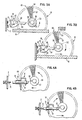
- FIG . 1 shows a top plane view of a rotary type of printer embodying the invention.
- the printer has left and right side plates 2 and 4, and a base 6, for housing the mechanical components, most of the electrical components and some of the electronic and logic parts of the machine. The rest of the circuits will be located in a separate housing not shown.
- a carriage assembly 8 is slidingly supported by a shaft 10, and can be shifted between said left and right side plates 2 and 4 by a belt and pulley assembly 12 driven by a carriage stepper motor 14.
- Carriage assembly 8 includes a base plate 16 which provides support for the rotatable type-face-carrier, e.g., printwheel 18, for a type-face-carrier rotation means, i.e., the selection stepper motor 20 which rotates the printwheel 18, for the hammer 22 and driver 23 assembly, and for a ribbon cartridge 24 interposing an inking ribbon 26 between printwheel 18 and record medium holder or platen 28.
- the platen 28 is rotatably secured to the side plates 2 and 4 to support the record medium (not shown).
- the platen 28 is provided with conventional platen knobs 30 and 31 and with automatic motion means (not shown) which enable rotating the platen to transfer the record or print receiving medium from one printing line position to another.
- the printer is also provided with a printwheel homing device including a first (58) - and a second (61) stop elements which will be described further on.
- feeding the carriage motion means, i.e., carriage stepper motor, 14 with signals provided by electronic and logic control circuitry (see FIG. 2)_ causes the belt and pulley assembly 12 to move the carriage assembly 8 from left to right or vice-versa along a print line direction and from one print position to the next.
- the printwheel 18 is also rotated about its axis by the selection stepper motor 20 for character selection purposes in order to present the pad bearing the character to be printed in front of a printing position on the record medium, and within the path of hammer 22.
- driving the driver 23 With the selected pad positioned, driving the driver 23 will make the hammer 22 strike the printing character against the inking ribbon 26 and print receiving medium and print the selected character.
- the two stepper motors 14 and 20 are driven by motor driver circuits 32 and 34 controlled by logic circuitry composed of one master microprocessor 36, two separate slave microprocessors 38 and 40 provided with associated external memories 42 and 44 and output ports 46 and 48 respectively. These slave microprocessors 38 and 40 are respectively intended for driving the carriage stepper motor 14 and the selection stepper motor 20. Other slave microprocessors (not shown) are used for performing other printer functions not involved in homing operations.
- the depressing of any character key (not shown) on the printer board 50 shown in FIG. 1 is detected and reported to the master microprocessor 36 as a command.
- the master microprocessor 36 identifies the command source, defines the functions to be performed and distributes the jobs to the slave microprocessors.
- the master microprocessor 36 is also kept aware of the evolution of the functions under performance by the slaves in order to synchronize these functions with each other.
- the slave microprocessors used to control stepper motor operations have to provide sequences of coded signals based on both the type of move to be performed by the stepper motor involved and the type of stepper motor used.
- each stepper motor is defined through a phase table Tl (not shownl comprising a set of binary words permanently stored into the internal memory of the associated slave microprocessor 38 or 40, while the corresponding external memory 42 or 44 stores profiles.
- a profile consists of a sequence of phase and time data selected by the designer for performing a specific and complete move or sequence of stepper motor steps with the best possible efficiency and reliability. Knowing the actual position of a stepper motor and the desired next position, the slave microprocessor controlling that stepper motor feeds the corresponding motor driver circuit with a sequence of data derived from a profile, which data are then converted by said motor driver circuit into sets or trains of time varying current pulses fed into the motor phase circuits in accordance with the indications of the phase table of the motor involved.
- the motor acceleration and speed rates depend on the shapes of the current pulse trains applied to selected motor phases.
- the motor direction of rotation depends on the order in which the different phases are switched on and off.
- the depressing of a character key on the printer board is reported to the master microprocessor 36 through its status and data input as a command issued from a command source.
- the carriage assembly Prior to any effective impact printing operation, the carriage assembly has to be moved along the print line to face the correct print position. This job is devoted to the slave microprocessor 38.
- the printwheel 18 has to be rotated to present the adequate pad to face the hammer 22. This function is devoted to the slave microprocessor 40. Both operations are initiated and synchronized by the master microprocessor 36.
- the selected character to be printed is identified by the master microprocessor 36 and this identity is reported to the slave microprocessor 40 which stores it into one of its internal registers (R2) while the identity of the last character printed has been transferred from register R2 into a register Rl.
- a table T2 (not shown) identifying the sequence of character distribution about the printwheel 18 periphery. Proper angular rotation of the printwheel 18 for character selection purposes involves the following operations to be controlled by the slave microprocessor 40. First the table T2 is consulted in order to determine the angular rotation to be performed by the printwheel 18 to move from the position identified by the contents of register Rl to the position identified by the contents of register R2.
- the profile in external memory 44 is addressed. This provides a selected microprogram to be read into the slave microprocessor 40, which then addresses the table Tl. The phase-table data is in turn used to control the stepper motor driver circuit 34 through the output ports 48.
- R2 is then shifted into Rl setting the system ready for a new character selection operation.
- the slave microprocessor 38 together with its external memory 42, the output ports 46 and the motor driver circuit 32 will drive the carriage stepper motor 14 to bring the carriage assembly 8 to the adequate position along the printing line.
- FIGS. 3A and 3B show one embodiment of the stop elements of the invention.
- a printwheel 18 comprising resilient pads 52 which support print characters 54 on their extremities is shown.
- the printwheel including a hub 56 is adapted to be made to rotate with the motor shaft 57 by the selection stepper motor 20 (FIG. 11, to bring any selected pad into a predetermined printing position located on the hammer 22 (FIG. 1) path.
- the printwheel hub 56 is provided with a first stop element or knob 58, which can be a .060 inch molded member fixed at any desired fixed angle from the printwheel home pad position. This knob 58 is attached to rotate with the printwheel 18.
- the home pad 60 has been selected to be the third pad to the left of the pad set into printing position when the printwheel 18 is stopped, as shown on FIG. 3B. But no matter what the printwheel home pad angular position is, the homing operation should identify and bring the home pad 60 with the printing position.
- a second stop element 61 is attached to the left side plate 2 of the printer housing.
- This second stop element 61 comprises essentially a bracket 62, carrying a latch 64.
- the bracket 62 is vertically adjustable while the latch 64 is horizontally adjustable.
- the latch 64 can rotate about an axis or pivot 66 parallel to the rotation axis of the printwheel 18.
- the farthest left position to be reached by the carriage assembly 8 of FIG. 1, i.e., the left printing margin position is such that, while the printwheel 18 rotates for character selection purposes, the knob 58 scans a path normally out of the space limits into which the latch 64 (see FIG. 3A) extends.
- This second stop element is shown on FIG. 3A in a rest position with a limiting member 68 forbidding the latch 64 to rotate clockwise any further under the impetus of a return spring 70.
- the logic control of FIG. 2, i.e., master-slave arrangement 36-38 and driver circuit 32 drives the carriage stepper motor 14 to bring the carriage assembly 8 to an extreme left position where the side plate 2 prevents the carriage assembly 8 from moving any further left by having the base plate 16 abutting against said side plate 2.
- the latch 64 engages into the rotary path limits which would be scanned by the knob 58 while the printwheel 18 would rotate (see dashed lines 59 on FIGS. 3A and 38).
- the printwheel selection stepper motor 20 may be detented or not during this time.
- the knob 58 is at random orientation. If the printwheel 18 rotates in clockwise direction, then the knob 58 might hit the latch 64 below the position shown on FIG. 3B. Then due to its chamfer shaped end, the latch 64 rotates about its pivot 66 in counterclockwise direction away from limiting member 68, to enable moving the carriage assembly 8 further to the desired extreme left position.
- the slave microprocessor 40 drives the selection stepper motor 20 with a fixed set of instructions such that said selection motor 20 would normally be stepped more than one revolution in counterclockwise direction.
- the selection stepper motor 20 might be still electrically driven until the end of the fixed set of instructions while it is mechanically non-rotating without this being detrimental to the motor.
- the printwheel 18 is made to rotate clockwise for a predetermined number of steps depending upon the angular position of the home pad 60 with respect to printing position in order to bring said home pad into printing position. ' This number of steps has been selected to be three with the arrangement of FIGS. 3A and 3B. Then the carriage assembly 8 is made to move to the left margin writing position (see FIG.
- FIGS. 4A and 4B show a simpler arrangement for the second stop element.
- An interposer 72 is now mounted on the carriage assembly 8 and an adjustable screw 74 is inserted into the left side plate 2.
- the interposer 72 is made to be slidable or reciprocable in a plane parallel to the path of first stop element 58 and is maintained out of said path under the impetus of a spring 76 except when the carriage is shifted to the left against the adjustable screw 74.
- FIG. 4A shows the second stop element with interposer 72 positioned out of the path of the knob 58 by the spring 76 being relaxed
- FIG. 4B shows the same second stop element with the spring 76 compressed whereby the interposer 72 is made to extend within the path of knob 58.
- homing operations are needed when the printer power is set on. But such a need may also occur while the printer is operating.
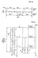
- the need for performing the homing operations will be decoded by the master microprocessor 36 detecting the occurrence of a predetermined event, e.g., the setting on of the printer electric power or the detection of a specific instruction. Upon detection of such an event, the master microprocessor 36 controls the logic flow between the two slave microprocessors 38 and 40, as shown on the timing diagram of FIG. 5.
- FIG. 5 shows a timing diagram for performing the printwheel 18 homing function using a 3-phase ninety six steps variable reluctance stepper motor as selection motor 20, and a 6-phase four hundred and twenty steps variable reluctance stepper motor as carriage motor 14.
- zones A through D show the timing schedule for the carriage motor 14, while zones E through H show the timing schedule for the selection motor 20 for the same period of time.
- the last printwheel step (Zone H) is only due to the fact that the home pad 60 has been selected to be three steps away from printing position when the first and second stop elements are made to come into contact with each other.
- the home pad 60 could be selected at any known angular position from the first stop element 58.
- stepper motors 14 and 20 cannot reach a given speed instantaneously. They should, first, be brought to that speed at a selected acceleration rate.
- the above functions are performed by having stored microprograms run the microprocessors to control the motor driver circuits 32 and 34 to feed the necessary time varying current signals into the motor coil phases.
- FIG . 6 shows a motor driver circuit arrangement for a three phase stepper motor.
- the motor driver circuit is made of three double transistor current amplifiers Tl-2, T3-4 and T5-6 driving the different motor phases.
- a resistor R is used on each motor phase to decrease the motor coil time constant, while a series diode-resistor arrangement R d is used on each motor phase 'to provide a return current path to the motor phase coil just turned off.
- microprocessors used may be conventional commercially available microprocessors such as Intel 8085 for the master function and Intel 8041 for the slave functions.
- Attached are a set of programs used for performing the homing function using the above mentioned Intel Systems.
- the main part of the attachment consists of two programs, one for the "SELECTION MOTOR” 20, the other for the “CARRIAGE MOTOR” 14.
- These programs call for subroutines such as SYGETPHS for initialization purposes; SYDELAY for counting delays; or SYSLEXPR.
- SYGETPHS and SYDELAY subroutines (not shown) are conventional initializing and counting routines.
- the "CARRIAGE MOTOR” program also requires two profiles designated by "Home Profile” and "Short Tab Profile” respectively.
- carriage assembly 8 could be driven to the right side frame extreme position to effect the homing operation although the left side frame extreme position is preferred due to its proximity to the normal print starting point.
Applications Claiming Priority (2)
| Application Number | Priority Date | Filing Date | Title |
|---|---|---|---|
| US102792 | 1979-12-12 | ||
| US06/102,792 US4264220A (en) | 1979-12-12 | 1979-12-12 | Printwheel homing apparatus |
Publications (3)
| Publication Number | Publication Date |
|---|---|
| EP0030626A2 true EP0030626A2 (de) | 1981-06-24 |
| EP0030626A3 EP0030626A3 (en) | 1983-03-16 |
| EP0030626B1 EP0030626B1 (de) | 1985-05-02 |
Family
ID=22291691
Family Applications (1)
| Application Number | Title | Priority Date | Filing Date |
|---|---|---|---|
| EP80107024A Expired EP0030626B1 (de) | 1979-12-12 | 1980-11-14 | Verfahren zum Zurückführen einer Druckscheibe in die Ausgangsstellung |
Country Status (4)
| Country | Link |
|---|---|
| US (1) | US4264220A (de) |
| EP (1) | EP0030626B1 (de) |
| CA (1) | CA1155962A (de) |
| DE (1) | DE3070591D1 (de) |
Cited By (4)
| Publication number | Priority date | Publication date | Assignee | Title |
|---|---|---|---|---|
| EP0058092A2 (de) * | 1981-02-11 | 1982-08-18 | Xerox Corporation | Rotierendes Druckelement, versehen mit Kodifizierungsangaben |
| DE3490763T1 (de) * | 1984-09-20 | 1987-02-19 | ||
| DE3538012A1 (de) * | 1985-10-25 | 1987-04-30 | Olympia Ag | Vorrichtung zur einstellung eines typenrades auf ein nullstellungs-bitmuster eines motors in einer schreib- oder bueromaschine aehnlicher bauart |
| EP0308633A2 (de) * | 1987-09-25 | 1989-03-29 | International Business Machines Corporation | Automatische Funktionskontrolle für eine elektronische Schreibmaschine |
Families Citing this family (19)
| Publication number | Priority date | Publication date | Assignee | Title |
|---|---|---|---|---|
| US4389129A (en) * | 1980-06-30 | 1983-06-21 | Brother Kogyo Kabushiki Kaisha | Type wheel printer |
| JPS5865683A (ja) * | 1981-10-15 | 1983-04-19 | Canon Inc | 印字装置 |
| DE3150541C2 (de) * | 1981-12-21 | 1985-12-12 | Olympia Werke Ag, 2940 Wilhelmshaven | Druckwerk für eine Schreib- oder ähnliche Büromaschine mit einem Typenrad |
| IT1145638B (it) * | 1981-12-30 | 1986-11-05 | Olivetti & Co Spa | Dispositivo di posizionamento per un organo di selezione di macchine stampanti |
| US4459054A (en) * | 1982-01-15 | 1984-07-10 | International Business Machines Corporation | Shared character selection, escapement and line advance system for serial printer |
| IT1165548B (it) * | 1983-02-22 | 1987-04-22 | Olivetti & Co Spa | Macchina per scrivere elettronica con dispositivo per il posizionamento di zero di un organo portacaratteri girevole |
| IT1158811B (it) * | 1983-02-28 | 1987-02-25 | Olivetti & Co Spa | Dispositivo per accoppiare un disco portacaratteri ad un motore di selezione |
| US4541746A (en) * | 1983-10-14 | 1985-09-17 | International Business Machines Corporation | Initializing apparatus for daisy wheel printer |
| JPS6116879A (ja) * | 1984-07-02 | 1986-01-24 | Sharp Corp | 電子式プリンタ |
| DE3606545C1 (de) * | 1986-02-28 | 1987-04-16 | Triumph Adler Ag | Vorrichtung zum Kuppeln eines Typenrades mit einer Dreheinstellwelle in Schreib- oder aehnlichen Maschinen |
| JPH088794B2 (ja) * | 1986-03-11 | 1996-01-29 | ブラザー工業株式会社 | ステツピングモ−タの停止制御方法 |
| JPS6352698A (ja) * | 1986-08-20 | 1988-03-05 | Brother Ind Ltd | ステツプモ−タの制御方法 |
| JPS63170069A (ja) * | 1987-01-07 | 1988-07-13 | Brother Ind Ltd | 活字ホイ−ル式印字装置 |
| US4859099A (en) * | 1987-10-22 | 1989-08-22 | Brother Kogyo Kabushiki Kaisha | Automatic paper loading apparatus for printer having paper bail actuating device |
| DE4226052C2 (de) * | 1991-08-06 | 1996-12-05 | Hitachi Ltd | Drucksteuerungsverfahren und -gerät, die eine Vielzahl von Prozessoren verwenden |
| JP3381348B2 (ja) * | 1993-12-27 | 2003-02-24 | セイコーエプソン株式会社 | プリンタ |
| US6232999B1 (en) | 1999-06-25 | 2001-05-15 | Eastman Kodak Company | Method for changing focus and angle of a multichannel printhead |
| US6249300B1 (en) | 1999-07-15 | 2001-06-19 | Eastman Kodak Company | Method and apparatus for positioning a writing assembly of an image processing apparatus |
| JP2005103792A (ja) * | 2003-09-29 | 2005-04-21 | Brother Ind Ltd | インクジェット記録装置 |
Citations (3)
| Publication number | Priority date | Publication date | Assignee | Title |
|---|---|---|---|---|
| FR2070622A5 (de) * | 1969-12-11 | 1971-09-10 | Ibm France | |
| US4091911A (en) * | 1976-05-03 | 1978-05-30 | Xerox Corporation | Control apparatus for serial printer |
| FR2383020A1 (fr) * | 1977-03-10 | 1978-10-06 | Adlerwerke Kleyer Ag H | Dispositif pour entrainer et commander un porte-caracteres, de preference sous forme d'un disque a caracteres, d'un mecanisme d'impression |
Family Cites Families (1)
| Publication number | Priority date | Publication date | Assignee | Title |
|---|---|---|---|---|
| GB1584136A (en) * | 1977-03-10 | 1981-02-04 | Alderwerke | System for positioning a type carrier |
-
1979
- 1979-12-12 US US06/102,792 patent/US4264220A/en not_active Expired - Lifetime
-
1980
- 1980-11-14 DE DE8080107024T patent/DE3070591D1/de not_active Expired
- 1980-11-14 EP EP80107024A patent/EP0030626B1/de not_active Expired
- 1980-12-03 CA CA000366018A patent/CA1155962A/en not_active Expired
Patent Citations (3)
| Publication number | Priority date | Publication date | Assignee | Title |
|---|---|---|---|---|
| FR2070622A5 (de) * | 1969-12-11 | 1971-09-10 | Ibm France | |
| US4091911A (en) * | 1976-05-03 | 1978-05-30 | Xerox Corporation | Control apparatus for serial printer |
| FR2383020A1 (fr) * | 1977-03-10 | 1978-10-06 | Adlerwerke Kleyer Ag H | Dispositif pour entrainer et commander un porte-caracteres, de preference sous forme d'un disque a caracteres, d'un mecanisme d'impression |
Cited By (7)
| Publication number | Priority date | Publication date | Assignee | Title |
|---|---|---|---|---|
| EP0058092A2 (de) * | 1981-02-11 | 1982-08-18 | Xerox Corporation | Rotierendes Druckelement, versehen mit Kodifizierungsangaben |
| EP0058092A3 (en) * | 1981-02-11 | 1984-03-28 | Xerox Corporation | Rotary print device with inherent indicia |
| DE3490763T1 (de) * | 1984-09-20 | 1987-02-19 | ||
| DE3538012A1 (de) * | 1985-10-25 | 1987-04-30 | Olympia Ag | Vorrichtung zur einstellung eines typenrades auf ein nullstellungs-bitmuster eines motors in einer schreib- oder bueromaschine aehnlicher bauart |
| EP0308633A2 (de) * | 1987-09-25 | 1989-03-29 | International Business Machines Corporation | Automatische Funktionskontrolle für eine elektronische Schreibmaschine |
| EP0308633A3 (de) * | 1987-09-25 | 1989-12-27 | International Business Machines Corporation | Automatische Funktionskontrolle für eine elektronische Schreibmaschine |
| AU607258B2 (en) * | 1987-09-25 | 1991-02-28 | International Business Machines Corporation | Automatic function control for an electronic typewriter |
Also Published As
| Publication number | Publication date |
|---|---|
| US4264220A (en) | 1981-04-28 |
| CA1155962A (en) | 1983-10-25 |
| EP0030626A3 (en) | 1983-03-16 |
| DE3070591D1 (en) | 1985-06-05 |
| EP0030626B1 (de) | 1985-05-02 |
Similar Documents
| Publication | Publication Date | Title |
|---|---|---|
| EP0030626B1 (de) | Verfahren zum Zurückführen einer Druckscheibe in die Ausgangsstellung | |
| US3630336A (en) | Proportional spacing printer incorporating word underscore control | |
| CA1092246A (en) | Data system with microprocessor featuring multiplexed data transfer and repeat cycle driving arrangement | |
| US4281938A (en) | Automatic print wheel element changing mechanism for a serial printer | |
| US4279523A (en) | Power recovery apparatus for an electric typewriter | |
| EP0134017A1 (de) | Mittels Mikroprozessor kontrolliertes Positionierungssystem | |
| US4602882A (en) | Control system of serial printer | |
| US4541746A (en) | Initializing apparatus for daisy wheel printer | |
| US4390293A (en) | Electronic typewriter | |
| US4279199A (en) | Print head image generator for printer subsystem | |
| US4311398A (en) | Printer for producing uniformly spaced characters | |
| US4053043A (en) | Means and method for enhancing ribbon lift | |
| US4605324A (en) | Electronic typewriter with a device for zero positioning of a rotary character-carrying device | |
| US3837457A (en) | Single element printer having a closed loop digital electronic control | |
| US5454653A (en) | Printing device having record medium feed means | |
| US3773161A (en) | High speed serial printer with plural hammers | |
| EP0098375B1 (de) | Kompensationsschaltung für Drucker mit verschiedenen Geschwindigkeiten | |
| EP0151425A2 (de) | Papierzufuhrsteuerung für einen Drucker | |
| US4688956A (en) | Carriage feed control method for bold and shadow printing | |
| US5147143A (en) | Printer carriage homing mechanism | |
| JPS62162556A (ja) | ワイヤ・マトリツクス・プリンタのワイヤ発射制御装置 | |
| US4440512A (en) | Daisy wheel printer having low mass carriage | |
| US3232222A (en) | Printing system having storage and blocking means | |
| KR900006929B1 (ko) | 데이지 휠형 인자장치 | |
| US4175488A (en) | Printer |
Legal Events
| Date | Code | Title | Description |
|---|---|---|---|
| PUAI | Public reference made under article 153(3) epc to a published international application that has entered the european phase |
Free format text: ORIGINAL CODE: 0009012 |
|
| AK | Designated contracting states |
Designated state(s): DE FR GB IT |
|
| 17P | Request for examination filed |
Effective date: 19810828 |
|
| PUAL | Search report despatched |
Free format text: ORIGINAL CODE: 0009013 |
|
| AK | Designated contracting states |
Designated state(s): DE FR GB IT |
|
| GRAA | (expected) grant |
Free format text: ORIGINAL CODE: 0009210 |
|
| AK | Designated contracting states |
Designated state(s): DE FR GB IT |
|
| PG25 | Lapsed in a contracting state [announced via postgrant information from national office to epo] |
Ref country code: IT Free format text: LAPSE BECAUSE OF FAILURE TO SUBMIT A TRANSLATION OF THE DESCRIPTION OR TO PAY THE FEE WITHIN THE PRESCRIBED TIME-LIMIT;WARNING: LAPSES OF ITALIAN PATENTS WITH EFFECTIVE DATE BEFORE 2007 MAY HAVE OCCURRED AT ANY TIME BEFORE 2007. THE CORRECT EFFECTIVE DATE MAY BE DIFFERENT FROM THE ONE RECORDED. Effective date: 19850502 |
|
| REF | Corresponds to: |
Ref document number: 3070591 Country of ref document: DE Date of ref document: 19850605 |
|
| ET | Fr: translation filed | ||
| PLBE | No opposition filed within time limit |
Free format text: ORIGINAL CODE: 0009261 |
|
| STAA | Information on the status of an ep patent application or granted ep patent |
Free format text: STATUS: NO OPPOSITION FILED WITHIN TIME LIMIT |
|
| 26N | No opposition filed | ||
| REG | Reference to a national code |
Ref country code: FR Ref legal event code: GC |
|
| REG | Reference to a national code |
Ref country code: GB Ref legal event code: 732 |
|
| REG | Reference to a national code |
Ref country code: FR Ref legal event code: TP |
|
| PGFP | Annual fee paid to national office [announced via postgrant information from national office to epo] |
Ref country code: FR Payment date: 19991019 Year of fee payment: 20 |
|
| PGFP | Annual fee paid to national office [announced via postgrant information from national office to epo] |
Ref country code: GB Payment date: 19991020 Year of fee payment: 20 Ref country code: DE Payment date: 19991020 Year of fee payment: 20 |
|
| PG25 | Lapsed in a contracting state [announced via postgrant information from national office to epo] |
Ref country code: GB Free format text: LAPSE BECAUSE OF EXPIRATION OF PROTECTION Effective date: 20001113 |
|
| REG | Reference to a national code |
Ref country code: GB Ref legal event code: PE20 Effective date: 20001113 |