EP0030491B1 - Correcteur électronique d'angle d'avance à l'allumage en fonction du cliquetis - Google Patents
Correcteur électronique d'angle d'avance à l'allumage en fonction du cliquetis Download PDFInfo
- Publication number
- EP0030491B1 EP0030491B1 EP80401686A EP80401686A EP0030491B1 EP 0030491 B1 EP0030491 B1 EP 0030491B1 EP 80401686 A EP80401686 A EP 80401686A EP 80401686 A EP80401686 A EP 80401686A EP 0030491 B1 EP0030491 B1 EP 0030491B1
- Authority
- EP
- European Patent Office
- Prior art keywords
- value
- stage
- shift
- engine
- pinking
- Prior art date
- Legal status (The legal status is an assumption and is not a legal conclusion. Google has not performed a legal analysis and makes no representation as to the accuracy of the status listed.)
- Expired
Links
- 230000001133 acceleration Effects 0.000 claims description 28
- 238000012937 correction Methods 0.000 claims description 24
- 238000001514 detection method Methods 0.000 claims description 23
- 230000015654 memory Effects 0.000 claims description 21
- 238000002485 combustion reaction Methods 0.000 claims description 19
- 238000004364 calculation method Methods 0.000 claims description 18
- 238000005259 measurement Methods 0.000 claims description 18
- 238000000034 method Methods 0.000 claims description 18
- 230000008569 process Effects 0.000 claims description 10
- 239000003990 capacitor Substances 0.000 claims description 8
- 238000012545 processing Methods 0.000 claims description 7
- 230000010354 integration Effects 0.000 claims description 6
- 230000004069 differentiation Effects 0.000 claims description 2
- 238000001914 filtration Methods 0.000 claims description 2
- 238000012360 testing method Methods 0.000 description 32
- 230000006870 function Effects 0.000 description 18
- 239000004020 conductor Substances 0.000 description 17
- 229910003460 diamond Inorganic materials 0.000 description 7
- 239000010432 diamond Substances 0.000 description 7
- GDOPTJXRTPNYNR-UHFFFAOYSA-N methyl-cyclopentane Natural products CC1CCCC1 GDOPTJXRTPNYNR-UHFFFAOYSA-N 0.000 description 7
- 230000006835 compression Effects 0.000 description 5
- 238000007906 compression Methods 0.000 description 5
- 239000000203 mixture Substances 0.000 description 5
- 230000007423 decrease Effects 0.000 description 4
- 238000010586 diagram Methods 0.000 description 3
- 230000001052 transient effect Effects 0.000 description 3
- 238000012886 linear function Methods 0.000 description 2
- 238000005457 optimization Methods 0.000 description 2
- 230000008520 organization Effects 0.000 description 2
- 230000001960 triggered effect Effects 0.000 description 2
- 230000008901 benefit Effects 0.000 description 1
- 230000033228 biological regulation Effects 0.000 description 1
- 230000005540 biological transmission Effects 0.000 description 1
- 230000008859 change Effects 0.000 description 1
- 238000004891 communication Methods 0.000 description 1
- 230000003247 decreasing effect Effects 0.000 description 1
- 239000006185 dispersion Substances 0.000 description 1
- 238000006073 displacement reaction Methods 0.000 description 1
- 230000005284 excitation Effects 0.000 description 1
- 239000000446 fuel Substances 0.000 description 1
- 230000006872 improvement Effects 0.000 description 1
- 230000002045 lasting effect Effects 0.000 description 1
- 230000004048 modification Effects 0.000 description 1
- 238000012986 modification Methods 0.000 description 1
- 230000007935 neutral effect Effects 0.000 description 1
- 230000003287 optical effect Effects 0.000 description 1
- 238000011084 recovery Methods 0.000 description 1
- 230000009467 reduction Effects 0.000 description 1
- 230000004044 response Effects 0.000 description 1
- 230000035945 sensitivity Effects 0.000 description 1
- 230000001360 synchronised effect Effects 0.000 description 1
Images


Classifications
-
- F—MECHANICAL ENGINEERING; LIGHTING; HEATING; WEAPONS; BLASTING
- F02—COMBUSTION ENGINES; HOT-GAS OR COMBUSTION-PRODUCT ENGINE PLANTS
- F02P—IGNITION, OTHER THAN COMPRESSION IGNITION, FOR INTERNAL-COMBUSTION ENGINES; TESTING OF IGNITION TIMING IN COMPRESSION-IGNITION ENGINES
- F02P5/00—Advancing or retarding ignition; Control therefor
- F02P5/04—Advancing or retarding ignition; Control therefor automatically, as a function of the working conditions of the engine or vehicle or of the atmospheric conditions
- F02P5/145—Advancing or retarding ignition; Control therefor automatically, as a function of the working conditions of the engine or vehicle or of the atmospheric conditions using electrical means
- F02P5/15—Digital data processing
- F02P5/152—Digital data processing dependent on pinking
- F02P5/1521—Digital data processing dependent on pinking with particular means during a transient phase, e.g. starting, acceleration, deceleration, gear change
-
- Y—GENERAL TAGGING OF NEW TECHNOLOGICAL DEVELOPMENTS; GENERAL TAGGING OF CROSS-SECTIONAL TECHNOLOGIES SPANNING OVER SEVERAL SECTIONS OF THE IPC; TECHNICAL SUBJECTS COVERED BY FORMER USPC CROSS-REFERENCE ART COLLECTIONS [XRACs] AND DIGESTS
- Y02—TECHNOLOGIES OR APPLICATIONS FOR MITIGATION OR ADAPTATION AGAINST CLIMATE CHANGE
- Y02T—CLIMATE CHANGE MITIGATION TECHNOLOGIES RELATED TO TRANSPORTATION
- Y02T10/00—Road transport of goods or passengers
- Y02T10/10—Internal combustion engine [ICE] based vehicles
- Y02T10/40—Engine management systems
Definitions
- the present invention relates to an electronic angle of advance advance on ignition of an internal combustion internal combustion engine with spark ignition as a function of the engine knock.
- the improvement of the combustion cycle has always preoccupied the engine manufacturer and has been one of the guiding elements of the modification of the architecture of the combustion chambers and the increase in the compression ratio. Indeed, this last parameter directly conditions the thermodynamic efficiency of the engine.
- the increase in the compression ratio displaces the area of knocking appearance towards the maximum of the curve of the applied torque. to the engine as a function of the ignition advance angle and, if the engine compression ratio is continued to increase, the advance protection guard in relation to the rattling leads to operating the engine with characteristics which penalize it more than with a lower compression rate.
- the technician acts either on the increase in the richness of the mixture, or on the decrease in the ignition advance.
- the first solution is implicitly implemented in the fuel metering device by means of a recovery pump which enriches the mixture during the acceleration phases and with the carburetor automatic devices acting in the vicinity of full load and which enrich also the mixture; the second solution is only really effective with current devices when the engine is running in steady state.
- the most effective method of measuring and detecting the appearance of rattling is by analyzing pressure signals in the combustion chambers.
- This solution is costly by the type of sensors it requires and by their number: one per cylinder. It is therefore preferable to analyze the vibrations of the cylinder head of the engine by means of an accelerometer of seismic type.
- the signal from the accelerometer is processed by a bandpass filter centered on the resonance frequency of the combustion chamber so as to eliminate as much as possible noise outside the resonance band of the combustion chamber.
- a single or full wave rectification transforms the alternating signal into a continuous signal. Examination of this signal shows a part due to combustion noise of variable amplitude as a function of the engine rotation speed and the ignition advance angle around the maximum of the pressure in a cylinder and a part variable amplitude depending on the engine speed corresponding to the excitation of the cylinder head by the valves.
- the integration of the accelerometer signal, filtered and rectified in an angular window centered around the maximum pressure in the cylinder makes it possible to increase the dynamics of the measure and to perform the analysis only in a zone where clicking is possible.
- a window starting in neutral hat (P.M.H.) of each cylinder and lasting between 30 and 40 degrees of crankshaft rotation gives acceptable results on all types of engines used. From the integrated signal and after comparison with a predetermined threshold, the presence of rattling can be detected electronically.
- FR-A-2 404 121 describes such a knock detection method for the automatic adjustment of the ignition advance of an internal combustion engine.
- EP-A-18 858 describes a method for calculating and adjusting the optimization of the ignition advance of an internal combustion engine by means of a knock detection system at using a sensor such as an accelerometer rigidly fixed on the cylinder head of the engine, remarkable process in that one makes undergo an analog treatment to the accelerometric signal comprising in particular the integration of the signal inside a specified window; the resulting signal is converted into digital form; a mean value C is calculated proportional to the x previous knocking; two comparison thresholds 5 1 and S 2 are calculated which are each a linear function of the mean value C calculated previously; we compare the integrated accelerometer value in digital form to each of these thresholds and we deduce the existence or absence of an audible knock and / or knock value which we then use to act on the programmed advance of electronic ignition.
- a system for calculating and adjusting the optimization of the ignition advance of an internal combustion engine by means of a knock detection system from a sensor such as an accelerometer rigidly fixed to the cylinder head of the engine, a remarkable system in that it comprises means for analog processing of the signal taken from the accelerometer, these means comprising in particular an integrator, logic means for controlling the integrator, an analog-digital converter and a microcomputer comprising in particular a sequencer, a stage for calculating an average value C proportional to the x previous knock, two stages for calculating comparison thresholds (S 1 , S 2 ) which are each a linear function of the average value C calculated previously and means for deducing therefrom the existence or absence of an audible knock and / or knock value.
- the invention aims to eliminate this drawback by means of a method implementing the known method of integrating the accelerometer signal into an angular window of determined length.
- the subject of the invention is a method of electronic correction of the advance angle on ignition of an internal combustion engine by means of the detection of combustion noise signals using a sensor such as an accelerometer rigidly fixed to the cylinder head of the engine, according to which the accelerometric signal is subjected to an analog treatment comprising in particular the integration in an angular window of measurement of determined width in order to deduce therefrom a value Ai of the noise signal integrated in said measurement window, characterized in that an average value S n of engine integrated noise S n is calculated for each cylinder from the noise values Ai relating to the cylinder considered, said average value S n of integrated noise being constantly updated by the last sample, according to the formula:
- S n-1 is the previous average value
- A is the last value taken from the integrated noise
- k is a digital filtering coefficient for updating the average value
- a knock detection threshold C is defined for the cylinder considered by the formula:
- k 3 is a multiplier and k 2 is an offset value
- the last integrated noise value A is compared with the only knock detection C defined from the value S n-1 relative to the cylinder in question, the point of advance on ignition of the cylinder in question is corrected, as a function of the result of the previous comparison,
- the cylinders are treated successively one by one for detection and the average value S n is calculated from data relating to a determined cylinder at a given time.
- This makes it possible to take into account the dispersions of sensitivity of the sensor used, the gain of the processing electronics, the noise specific to the same type of engine, the transmission of noise through the cylinder head, the position of the accelerometer on the engine cylinder head and the noise level specific to each cylinder.
- Any mode of generation of the window can be used such as PLL loop with phase lock synchronized on a TDC signal, optical encoder, or generation from the electronic ignition associated with the present invention as it is carried out.
- the pressure in the intake manifold is measured and stored in each cycle, a differentiation is made with respect to the value stored in the previous cycle, it is deduced therefrom that we are accelerating if the derivative is positive, decelerating if the derivative is negative and in steady state if the derivative is zero, we compare the measured value of the pressure to a fixed threshold and we deduce that we is operating at full load or partial load depending on the result of said comparison.
- the offset value of all the cylinders in the acceleration phase and of the only cylinder considered in steady state is increased.
- a time delay is triggered during each acceleration, which blocks the resetting of the offset values during the deceleration phases immediately following an acceleration phase.
- the invention also relates to an electronic ignition advance angle corrector specially designed for the implementation of the method defined above, comprising a sensor such as an accelerometer rigidly fixed to the cylinder head of the engine, means for analog processing of the signal taken from the accelerometer, these analog processing means comprising an integrator receiving the accelerometer signal; a circuit generating a threshold value and a voltage level comparator, said corrector further comprising logic means for controlling the operation of the integrator within an angular measurement window, and a microcomputer which calculates the offset value of the ignition advance angle as a function of the output state of the comparataur, characterized in that the integrator comprises an integration capacity in which the detected noise signal is stored from the accelerometer and which is then discharged by a constant current system, and in that the microcomputer includes an internal oscillator, a counter which counts the pulses emitted by the internal oscillator during the time when the charge value of the capacitance is greater than the threshold value generated by the circuit, the content of said counter being representative of the value A, of the signal integrated in the measurement window
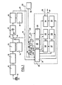
- an accelerometer 10 of piezoelectric nature screwed onto the cylinder head of an internal combustion engine which has not been shown, in an appropriate location, is connected by its output to a charge amplifier 11 itself connected to a bandpass filter 12 active for example in the frequency band from 6 to 9 kHz.
- the output of the bandpass filter 12 is connected at the input to a re blocker 13 connected to an integrator 15 via a switch 34, a second input terminal 41 of which is connected to a constant current generator 14 so as to be able to discharge a constant current capacitor 42 located in the integrator 15 which is loaded with the signal from the accelerometer 10 after the latter has been amplified, filtered rectified and integrated during the passage of a measurement window whose duration is controlled from point 30 by a conductor 31 acting on the position of the movable arm of the switch 34.
- the integrator 15 is connected by its output to the first input of a comparator 16 receiving on its second input a comparison threshold value established in a circuit 17.
- the output of the comparator 16 is connected by a conductor 43, on the one hand, to an input of a control logic 21 located inside a microcomputer 20 which is, for example, of the type 8048 of the American firm "INTEL", d on the other hand, at a first entry of a logic gate 35 with AND function connected by a second input 46 to an output of the control logic 21.
- the microcomputer 20 further comprises the following stages: an internal oscillator 22 and a counter 23, a calculation stage 24 of the mean noise value, a stage 27 for calculating the knock detection threshold, a stage 28 for calculating the value of the ignition advance offset signal, a data memory 25, an output stage 26 for the offset value and a memory 29 of the offset value.
- the control logic 21 is connected by a second input to the conductor 31 for controlling the position of the switch 34 and by its outputs to the computing stages 24, 27 and 28 to the memories 25 and 29 and by a conductor 45 to an input of a second logic gate 38 with AND function connected by its second input and a conductor 33 to a pressure sensor 32 which measures the pressure in the intake manifold of the engine.
- the internal oscillator 22 is connected by a first output to the output stage 26 of the offset value and by a second output to the first input of a third logic gate 36 with AND function connected by its second input to the output from the first logic gate 35 with AND function and by its output to the first input of a logic gate 37 with OR function connected by its second input to the output of the second logic gate 38 with AND function and by its output 44 to a input of the counter 23 which is connected by its output to the data memory 25.
- the data memory 25 is in communication with the stage for calculating the average noise value 24 and with the stage for calculating the offset value 28, the latter in connection with an input with the stage for calculating the knock detection threshold 27 and by an output to the memory of the offset value 29, the latter in relation by an output with the output stage 26 of the offset value.
- This last output stage 26 on receipt of a "send" signal, transmitted on a conductor 39, transmits on its output conductor 40 a number of pulses equal to the offset value calculated in the direction of the central computer of value d 'ignition advance angle.
- the start of the organization chart is referenced D; an arrow accompanied by such a letter, as is the case at the bottom of Figure 2, signifies a return to the dregs of the flowchart.
- the various connection tests carried out by comparator members are marked in the form of a diamond with a vertical diagonal, while the operations are marked in the form of rectangles.
- the test result is marked 1 in the case where it is positive and 0 in the case where it is negative and determines the different connection paths.
- a first step 210 the system is waiting for the start of the measurement window, communicated by the conductor 31 of FIG. 1.
- the pulses delivered by the pressure sensor 32 are authorized to be counted in the counter 23 after the signal has passed through the logic gates 38 and 37 for a determined time.
- the counter 23 works as a frequency meter so as to obtain a numerical value which translates the pressure of the air in the intake manifold.
- the knock measurement window is placed just after the P.M.H. and lasts for example 32 ° flywheel.
- the signal transmitted by the conductor 31 connects directly, via the switch 34, the integrator 15 to the output of the rectifier 13.
- the following diamond 212 materializes the wait for the end of the window which occurs on the arrival of a low logic level signal on the conductor 31 of FIG. 1.
- the next step 213 is triggered. It corresponds to the beginning of the decreasing ramp of the integrator 15, that is to say that, by the switch 34, the constant current generator 14 is connected to the input of the integrator 15 and causes the discharge of the capacitor. 42 which loaded previously. Via the driver 46 of the control logic output 21 of FIG.
- the pulses delivered by the internal oscillator 22 are authorized via logic gates 35 and 36 with AND function to be counted in the counter 23 during the time when the charge value of the capacitor 42 the integrator 15 is greater than the comparison threshold given at the output of the stage 17.
- the counter 23 then works as a period meter in order to assess the duration of discharge of the capacitor 42 which is the measurement of the maximum voltage to which it was previously charged and which corresponds to the value integrated noise in the measurement window determined from the input 30.
- the control logic 21 engages the calculation of the knock threshold in the stage 27 of the microcomputer during the discharge time of the capacitor 42.
- the diamond 215 corresponds to waiting for the end of the noise voltage measurement.
- step 216 This measurement, once completed, allows the passage to step 216 where the control logic 21 engages the calculation of the offset value in stage 28 of the microcomputer 20.
- the following diamond 218 corresponds to a test on the detection of knocking.
- the last step 219 corresponds to the calculation of the average noise value in the stage 24 of the microcomputer 20 and this calculation does not take place if there has been a knock detection. In the presence of rattling, this last step 219 is suppressed.
- FIG. 3 is a flowchart illustrating the operation of the computation stage 24 of the average noise value inside the microcomputer 20.
- This computation stage 24 includes a storage memory 240 of the average noise value S n - i and a storage memory 241 of the instantaneous noise value A I , both connected by their outputs in parallel to the inputs of a stage 242 in which the calculation of the difference A 1 is carried out S n-1 .
- a stage 244 selects a divider value k introduced in a stage 243 called division module which is also connected to the output of stage 242 giving the value of the difference A i - S n-1 .
- the division module 243 is connected by its output to a stage 245 in which the calculation of the new noise value is carried out according to the formula:
- This stage 245 is connected by the conductor 247 to the output of stage 242 in which the calculation of the difference A i - S n-1 to receive the sign and also to the storage memory 240 via the link 248 to receive the previous average noise value Sn-i.
- the calculation stage 24 ends with a stage 246 representing a step during which the new average value S " which has just been calculated is stored in the memory 240 in anticipation of the following calculation.
- FIG. 4 is a flowchart giving the detail of the calculation stage 27 of the knock threshold value inside the microcomputer 20.
- This new calculation stage firstly comprises a memory 240 of the average noise value which is that used in the preceding computation stage 24.
- the memory 240 is connected by its output to the input of a stage 271 in which the multiplication k 3 takes place .
- S n - 1 then from stage 271, we go to stage 272 where we add the value k 2 to the quantity previously calculated.
- the computation stage 27 ends with a memory 275 for storing the knock threshold value C which therefore meets the equation: where k 2 is an offset value and k 3 is a multiplier.
- FIG. 5 is a flow diagram of the calculation stage 28 of the offset correction value inside the microcomputer 20 applying a strategy as a function of the pressure, the knock and the operating cycle in which we are, namely: acceleration, deceleration, steady or non-stabilized load speed, partial load or full load speed.
- a strategy as a function of the pressure, the knock and the operating cycle in which we are, namely: acceleration, deceleration, steady or non-stabilized load speed, partial load or full load speed.
- the value m o varies from 400 to 800 ignition strokes.
- the OFFSET test is carried out: find out whether or not there is an advance offset. If there is indeed an offset, we go to station 346 where we decrease the offset every m 1 ignitions, m 1 being a numerical value between 150 and 300.
- the CLIQUETIS test in 334 which we arrive directly if the DECAL test in 345 gives a zero result. If the test 334 is positive, we pass to operation 335 during which we increase all the shifts of the quantity n 1 , n 1 being a numerical value between 6 and 8. After which we make a second test on DECAL for determining a maximum offset value in No. 338. If the test is positive, we arrive at 339 where the operation is to reduce the shift No. maximum value, after which the present cycle is finished.
- tests 334 and 338 have revealed a negative result, we leave the organization chart. If test 324 did not reveal an acceleration, we go to test 341 on TIMING.
- TEMP register Using the TEMP register, a transient acceleration is temporarily stored, which can facilitate engine operation by relieving it for the immediate future. Indeed, if we imagine on the part of the driver the following driving scenario: it accelerates and causes clicking; immediately after it releases the foot to change speed then accelerates again; the engine then takes advantage a second time of the correction established during the previous acceleration to cross the course of the second acceleration without clicking.
- the TEMPO register corresponds to a digital monostable which is decremented as soon as there is no acceleration.
- the TEMPO register is a digital monostable which is brought to its maximum by an acceleration and which makes it possible to inhibit any offset reset operation when one is in deceleration mode.
- test 344 If the test on TEMPO is positive, we go to 344 where the operation consists in decrementing the TEMPO register at each ignition. If test 341 gives a zero result, we go to 343 where the operation consists in bringing all the offsets to zero. Operations 343 and 344 have a common output which brings them directly to the end of the flowchart.
- test 323 revealed instability in the pressure regime. We now move on to examining the strategy when test 323 reveals that the pressure is stable. We leave diamond 323 on the right to reach test 325 on TEMPO. If this is not zero, we come to operation 326 which consists in decrementing the TEMPO as in operation 344.
- the output of operation 326 joins the left output of test 325, case where the TEMPO is zero, and this common leads to test 327 consisting of seeing whether or not the internal combustion engine is running at full load. The result is two slightly different strategies, although following parallel paths.
- test 329 establishes whether or not there is OFFSET of the ignition advance. If it is found that there is indeed an offset, operation 331 consists in decrementing the offset every m 3 ignitions, m 3 is a numerical quantity whose value is between 1000 and 2000. The output of l operation 331 joins the left output of test 329 in the case where there is a zero offset and then we go to test 332 to determine whether or not there is CLICKED. If so, we go to operation 337 which consists in increasing the OFFSET for the cylinder considered by the quantity n 3 , positive value equal to one or two. At the end of operation 337, we pass to test 338 already encountered previously during which the maximum value of the offset is determined. If test 332, like test 334 previously encountered, makes it possible to establish that there is no rattling, the present cycle is terminated.
- test 327 on FULL LOAD revealed that you are not in this condition, you go to the left to test 328 to determine whether or not there is OFFSET. If it is observed that there is indeed an offset, the operation 330 consists in decrementing this offset every m 2 ignitions, m 2 is a digital quantity whose value is between 400 and 800. The output of the operation 330 joins the left output of test 328 in the case where there is a zero offset and then we pass to test 333 to determine whether or not there is CLICK. If so, we go to operation 336 which consists in increasing the offset for the cylinder considered by the quantity n 2 , a positive value which can range from three to five.
- test 338 already encountered previously, during which the maximum value of the offset is determined. If test 333, like tests 332 and 334 already encountered, makes it possible to establish that there is no rattling, the present cycle is ended.
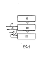
- FIG. 6 represents an embodiment of the output stage 26 of the computer 20.
- This stage 26 working in an operating mode by external interruption is not indicated in the flow diagram of FIG. 2 because its location is not not defined in the sequence of logical tasks but is defined by the main ignition advance computer when a corrected offset value is required.
- the conductor 39 called the send conductor arrives at the loading input of a down counter 260 connected by its inputs to a memory 29 of the offset value and by its outputs to a zero detector 261.
- the output of the latter is connected to an input of a logic gate 262 with AND function, the second input of which receives the pulses generated by the internal clock of the microcomputer 20.
- the output of this AND gate 262 is connected to the clock input of the downcounter 260 which is also linked for the conductor 40 with the output of the microcomputer 20 which transmits the offset value to the main ignition advance angle computer.
Landscapes
- Engineering & Computer Science (AREA)
- Signal Processing (AREA)
- Chemical & Material Sciences (AREA)
- Combustion & Propulsion (AREA)
- Mechanical Engineering (AREA)
- General Engineering & Computer Science (AREA)
- Combined Controls Of Internal Combustion Engines (AREA)
- Electrical Control Of Ignition Timing (AREA)
Applications Claiming Priority (2)
| Application Number | Priority Date | Filing Date | Title |
|---|---|---|---|
| FR7930179 | 1979-10-12 | ||
| FR7930179A FR2471485A1 (fr) | 1979-12-10 | 1979-12-10 | Correcteur electronique d'angle d'avance a l'allumage en fonction du cliquetis et de la charge d'un moteur |
Publications (2)
| Publication Number | Publication Date |
|---|---|
| EP0030491A1 EP0030491A1 (fr) | 1981-06-17 |
| EP0030491B1 true EP0030491B1 (fr) | 1985-05-02 |
Family
ID=9232557
Family Applications (1)
| Application Number | Title | Priority Date | Filing Date |
|---|---|---|---|
| EP80401686A Expired EP0030491B1 (fr) | 1979-12-10 | 1980-11-26 | Correcteur électronique d'angle d'avance à l'allumage en fonction du cliquetis |
Country Status (4)
| Country | Link |
|---|---|
| US (1) | US4347820A (enExample) |
| EP (1) | EP0030491B1 (enExample) |
| DE (1) | DE3070596D1 (enExample) |
| FR (1) | FR2471485A1 (enExample) |
Families Citing this family (22)
| Publication number | Priority date | Publication date | Assignee | Title |
|---|---|---|---|---|
| FR2510669B1 (fr) * | 1981-07-30 | 1986-10-03 | Marchal Equip Auto | Dispositif d'allumage evitant le cliquetis au cours du fonctionnement d'un moteur a combustion interne |
| FR2511435B1 (fr) * | 1981-08-11 | 1986-06-06 | Marchal Equip Auto | Procede de modification de l'angle de decalage d'allumage pour eviter le cliquetis dans un moteur a combustion interne et dispositif correspondant |
| US4513721A (en) * | 1981-08-11 | 1985-04-30 | Nippon Soken, Inc. | Air-fuel ratio control device for internal combustion engines |
| DE3142082A1 (de) * | 1981-10-23 | 1983-05-11 | Daimler-Benz Ag, 7000 Stuttgart | Verfahren einer antiklopfregelung fuer brennkraftmaschinen und vorrichtung zur durchfuehrung dieses verfahrens |
| JPS58144652A (ja) * | 1982-02-24 | 1983-08-29 | Hitachi Ltd | ノツク制御装置 |
| FR2524557B1 (fr) * | 1982-03-31 | 1987-05-29 | Mitsubishi Electric Corp | Dispositif de controle de cognement pour un moteur a combustion interne |
| JPS58187554A (ja) * | 1982-04-26 | 1983-11-01 | Mazda Motor Corp | エンジンの制御装置 |
| JPS58217775A (ja) * | 1982-06-09 | 1983-12-17 | Nippon Denso Co Ltd | 内燃機関の点火時期制御方法 |
| JPS58217773A (ja) * | 1982-06-11 | 1983-12-17 | Hitachi Ltd | 電子式エンジン制御装置 |
| FR2530736B1 (fr) * | 1982-07-20 | 1987-03-27 | Renault | Procede d'optimalisation de l'avance a l'allumage pour moteur a combustion interne |
| JPS59206648A (ja) * | 1983-01-26 | 1984-11-22 | Nissan Motor Co Ltd | 内燃機関の燃焼室内圧力を検出するセンサの較正方法 |
| US4675821A (en) * | 1983-02-18 | 1987-06-23 | Toyota Jidosha Kabushiki Kaisha | Method and apparatus for detecting knocking |
| JPS59185874A (ja) * | 1983-04-08 | 1984-10-22 | Hitachi Ltd | 内燃機関の点火装置 |
| IT1213129B (it) * | 1984-01-20 | 1989-12-14 | Alfa Romeo Spa | Dispositivo per la correzione di grandezze funzionali in un motore acombustione interna |
| JPS60201072A (ja) * | 1984-03-23 | 1985-10-11 | Hitachi Ltd | 内燃機関の点火装置 |
| FR2571141B1 (fr) * | 1984-10-02 | 1988-01-22 | Renault | Procede de diagnostic d'un systeme de detection de cliquetis |
| EP0550411B1 (en) * | 1988-06-14 | 1997-03-05 | Nippondenso Co., Ltd. | Knock control system for internal combustion engine |
| JPH03138436A (ja) * | 1989-10-24 | 1991-06-12 | Mitsubishi Electric Corp | 内燃機関用ノック検出装置及びそのフェール検出方法 |
| KR940000346B1 (ko) * | 1989-10-30 | 1994-01-17 | 미쓰비시덴키 가부시키가이샤 | 내연기관용 녹(Knock) 제어장치 |
| FR2727161B1 (fr) * | 1994-11-23 | 1996-12-20 | Siemens Automotive Sa | Procede de retour a l'avance nominale, en l'absence de detection de cliquetis |
| KR101316281B1 (ko) * | 2011-12-13 | 2013-10-08 | 아주대학교산학협력단 | 디젤엔진의 연소 제어 방법 |
| CN119353094B (zh) * | 2024-10-17 | 2025-09-30 | 东风汽车集团股份有限公司 | 发动机主动介入核查方法及装置 |
Family Cites Families (5)
| Publication number | Priority date | Publication date | Assignee | Title |
|---|---|---|---|---|
| US4002155A (en) * | 1976-01-12 | 1977-01-11 | General Motors Corporation | Engine and engine spark timing control with knock limiting etc. |
| JPS6060025B2 (ja) * | 1977-10-19 | 1985-12-27 | 株式会社日立製作所 | 自動車制御方法 |
| US4282841A (en) * | 1978-06-27 | 1981-08-11 | Nissan Motor Company, Limited | Ignition timing control system for an internal combustion engine |
| JPS5519978A (en) * | 1978-08-01 | 1980-02-13 | Nissan Motor Co Ltd | Ignition time controller |
| DE3069821D1 (en) * | 1979-05-25 | 1985-01-31 | Hitachi Ltd | Method and apparatus for controlling the ignition timing of internal combustion engines |
-
1979
- 1979-12-10 FR FR7930179A patent/FR2471485A1/fr active Granted
-
1980
- 1980-11-26 DE DE8080401686T patent/DE3070596D1/de not_active Expired
- 1980-11-26 EP EP80401686A patent/EP0030491B1/fr not_active Expired
- 1980-12-10 US US06/215,057 patent/US4347820A/en not_active Expired - Lifetime
Also Published As
| Publication number | Publication date |
|---|---|
| EP0030491A1 (fr) | 1981-06-17 |
| FR2471485B1 (enExample) | 1984-12-07 |
| DE3070596D1 (en) | 1985-06-05 |
| US4347820A (en) | 1982-09-07 |
| FR2471485A1 (fr) | 1981-06-19 |
Similar Documents
| Publication | Publication Date | Title |
|---|---|---|
| EP0030491B1 (fr) | Correcteur électronique d'angle d'avance à l'allumage en fonction du cliquetis | |
| US5230316A (en) | Method and apparatus for detecting knock in an internal combustion engine | |
| EP1548418B9 (fr) | Système de calibrage d'une chaîne d'acquisition de la pression dans un cylindre de moteur Diesel de véhicule automobile | |
| EP1918688B1 (en) | Misfire detecting apparatus for internal combustion engine | |
| US5287837A (en) | Knock suppressing apparatus for internal combustion engine | |
| FR2740509A1 (fr) | Procede d'adaptation permettant de corriger les ecarts de tolerance d'une roue-emetteur | |
| JPS639679A (ja) | 内燃機関の点火時期制御方法 | |
| EP0647774A1 (fr) | Système d'acquisition et de traitement instantané de données pour le contrôle d'un moteur à combustion interne | |
| FR2524557A1 (fr) | Dispositif de controle de cognement pour un moteur a combustion interne | |
| FR2524554A1 (fr) | Appareil de reglage du fonctionnement d'un moteur a combustion interne | |
| FR2554235A1 (fr) | Procede pour la detection de cylindres fonctionnant avec une combustion irreguliere dans un moteur a combustion interne et dispositif pour la mise en oeuvre de ce procede | |
| WO2018172665A1 (fr) | Procédé pour gérer du cliquetis dans un moteur à combustion interne à allumage commandé | |
| EP2898306B1 (fr) | Procede de traitement d'un signal d'un dispositif de mesure de pression au sein d'un moteur a combustion interne | |
| FR2937684A1 (fr) | Procede de determination de la duree d'une dent longue d'une cible montee sur un vilebrequin de moteur a combustion interne | |
| FR2548273A1 (fr) | Procede pour commander l'etat de fonctionnement d'un moteur a combustion interne | |
| EP0029374B1 (fr) | Générateur de signal de correction d'angle d'avance à l'allumage sous l'action de cliquetis | |
| FR2734326A1 (fr) | Procede de detection des rates a l'allumage d'un moteur a combustion interne a plusieurs cylindres | |
| FR2877086A1 (fr) | Procede pour determiner une pression de la chambre de combustion | |
| EP0128817B1 (fr) | Procédé de réglage et de mesure du vieillissement d'un moteur à combustion interne | |
| EP0577485A1 (fr) | Sonde destinée au contrôle d'un moteur à combustion interne | |
| WO2008050033A2 (fr) | Procede de recalage d'injecteurs d'un moteur et vehicule automobile le mettant en oeuvre | |
| FR3118102A1 (fr) | Procédé de détermination d’un indicateur de cliquetis de la combustion à partir de mesures d'accélération | |
| EP0695865A1 (fr) | Procédé de correction des dissymétries d'une roue de capteur | |
| EP0732573B1 (fr) | Procédé et dispositif de reconnaissance de signaux de vibrations, par exemple les cliquetis d'un moteur à combustion interne | |
| FR2656379A1 (fr) | Dispositif pour la commande et/ou la regulation du dosage du carburant et/ou de l'angle d'allumage d'un moteur a combustion interne. |
Legal Events
| Date | Code | Title | Description |
|---|---|---|---|
| PUAI | Public reference made under article 153(3) epc to a published international application that has entered the european phase |
Free format text: ORIGINAL CODE: 0009012 |
|
| AK | Designated contracting states |
Designated state(s): DE GB IT SE |
|
| 17P | Request for examination filed |
Effective date: 19810418 |
|
| ITF | It: translation for a ep patent filed | ||
| GRAA | (expected) grant |
Free format text: ORIGINAL CODE: 0009210 |
|
| AK | Designated contracting states |
Designated state(s): DE GB IT SE |
|
| REF | Corresponds to: |
Ref document number: 3070596 Country of ref document: DE Date of ref document: 19850605 |
|
| PLBE | No opposition filed within time limit |
Free format text: ORIGINAL CODE: 0009261 |
|
| STAA | Information on the status of an ep patent application or granted ep patent |
Free format text: STATUS: NO OPPOSITION FILED WITHIN TIME LIMIT |
|
| 26N | No opposition filed | ||
| ITTA | It: last paid annual fee | ||
| EAL | Se: european patent in force in sweden |
Ref document number: 80401686.3 |
|
| PGFP | Annual fee paid to national office [announced via postgrant information from national office to epo] |
Ref country code: GB Payment date: 19961014 Year of fee payment: 17 |
|
| PGFP | Annual fee paid to national office [announced via postgrant information from national office to epo] |
Ref country code: SE Payment date: 19961024 Year of fee payment: 17 Ref country code: DE Payment date: 19961024 Year of fee payment: 17 |
|
| PG25 | Lapsed in a contracting state [announced via postgrant information from national office to epo] |
Ref country code: GB Free format text: LAPSE BECAUSE OF NON-PAYMENT OF DUE FEES Effective date: 19971126 |
|
| PG25 | Lapsed in a contracting state [announced via postgrant information from national office to epo] |
Ref country code: SE Free format text: LAPSE BECAUSE OF NON-PAYMENT OF DUE FEES Effective date: 19971127 |
|
| GBPC | Gb: european patent ceased through non-payment of renewal fee |
Effective date: 19971126 |
|
| PG25 | Lapsed in a contracting state [announced via postgrant information from national office to epo] |
Ref country code: DE Free format text: LAPSE BECAUSE OF NON-PAYMENT OF DUE FEES Effective date: 19980801 |
|
| EUG | Se: european patent has lapsed |
Ref document number: 80401686.3 |