EP0030264B1 - Verfahren zum Imprägnieren von Fasersträngen und Faserbändern - Google Patents
Verfahren zum Imprägnieren von Fasersträngen und Faserbändern Download PDFInfo
- Publication number
- EP0030264B1 EP0030264B1 EP80106428A EP80106428A EP0030264B1 EP 0030264 B1 EP0030264 B1 EP 0030264B1 EP 80106428 A EP80106428 A EP 80106428A EP 80106428 A EP80106428 A EP 80106428A EP 0030264 B1 EP0030264 B1 EP 0030264B1
- Authority
- EP
- European Patent Office
- Prior art keywords
- chamber
- fibre
- resin
- conducted
- bands
- Prior art date
- Legal status (The legal status is an assumption and is not a legal conclusion. Google has not performed a legal analysis and makes no representation as to the accuracy of the status listed.)
- Expired
Links
- 238000000034 method Methods 0.000 title claims description 22
- 239000000835 fiber Substances 0.000 claims description 34
- 229920005989 resin Polymers 0.000 claims description 18
- 239000011347 resin Substances 0.000 claims description 18
- 229920003002 synthetic resin Polymers 0.000 claims description 11
- 239000000057 synthetic resin Substances 0.000 claims description 11
- 239000007788 liquid Substances 0.000 claims 1
- 238000010992 reflux Methods 0.000 claims 1
- 238000005470 impregnation Methods 0.000 description 17
- 238000007789 sealing Methods 0.000 description 6
- 210000002445 nipple Anatomy 0.000 description 4
- 238000004804 winding Methods 0.000 description 4
- 239000003085 diluting agent Substances 0.000 description 3
- PPBRXRYQALVLMV-UHFFFAOYSA-N Styrene Chemical compound C=CC1=CC=CC=C1 PPBRXRYQALVLMV-UHFFFAOYSA-N 0.000 description 2
- 101100390736 Danio rerio fign gene Proteins 0.000 description 1
- 229920001875 Ebonite Polymers 0.000 description 1
- 229920002430 Fibre-reinforced plastic Polymers 0.000 description 1
- 101100390738 Mus musculus Fign gene Proteins 0.000 description 1
- 230000004888 barrier function Effects 0.000 description 1
- 239000013013 elastic material Substances 0.000 description 1
- 239000011151 fibre-reinforced plastic Substances 0.000 description 1
- 239000006260 foam Substances 0.000 description 1
- 238000003780 insertion Methods 0.000 description 1
- 230000037431 insertion Effects 0.000 description 1
- 238000010030 laminating Methods 0.000 description 1
- 239000000463 material Substances 0.000 description 1
- 229920001225 polyester resin Polymers 0.000 description 1
- 239000004645 polyester resin Substances 0.000 description 1
- 238000002791 soaking Methods 0.000 description 1
- 239000002904 solvent Substances 0.000 description 1
- 238000009423 ventilation Methods 0.000 description 1
Images
Classifications
-
- B—PERFORMING OPERATIONS; TRANSPORTING
- B29—WORKING OF PLASTICS; WORKING OF SUBSTANCES IN A PLASTIC STATE IN GENERAL
- B29C—SHAPING OR JOINING OF PLASTICS; SHAPING OF MATERIAL IN A PLASTIC STATE, NOT OTHERWISE PROVIDED FOR; AFTER-TREATMENT OF THE SHAPED PRODUCTS, e.g. REPAIRING
- B29C70/00—Shaping composites, i.e. plastics material comprising reinforcements, fillers or preformed parts, e.g. inserts
- B29C70/04—Shaping composites, i.e. plastics material comprising reinforcements, fillers or preformed parts, e.g. inserts comprising reinforcements only, e.g. self-reinforcing plastics
- B29C70/28—Shaping operations therefor
- B29C70/40—Shaping or impregnating by compression not applied
- B29C70/50—Shaping or impregnating by compression not applied for producing articles of indefinite length, e.g. prepregs, sheet moulding compounds [SMC] or cross moulding compounds [XMC]
- B29C70/52—Pultrusion, i.e. forming and compressing by continuously pulling through a die
- B29C70/523—Pultrusion, i.e. forming and compressing by continuously pulling through a die and impregnating the reinforcement in the die
-
- B—PERFORMING OPERATIONS; TRANSPORTING
- B29—WORKING OF PLASTICS; WORKING OF SUBSTANCES IN A PLASTIC STATE IN GENERAL
- B29B—PREPARATION OR PRETREATMENT OF THE MATERIAL TO BE SHAPED; MAKING GRANULES OR PREFORMS; RECOVERY OF PLASTICS OR OTHER CONSTITUENTS OF WASTE MATERIAL CONTAINING PLASTICS
- B29B15/00—Pretreatment of the material to be shaped, not covered by groups B29B7/00 - B29B13/00
- B29B15/08—Pretreatment of the material to be shaped, not covered by groups B29B7/00 - B29B13/00 of reinforcements or fillers
- B29B15/10—Coating or impregnating independently of the moulding or shaping step
- B29B15/12—Coating or impregnating independently of the moulding or shaping step of reinforcements of indefinite length
- B29B15/122—Coating or impregnating independently of the moulding or shaping step of reinforcements of indefinite length with a matrix in liquid form, e.g. as melt, solution or latex
-
- D—TEXTILES; PAPER
- D06—TREATMENT OF TEXTILES OR THE LIKE; LAUNDERING; FLEXIBLE MATERIALS NOT OTHERWISE PROVIDED FOR
- D06B—TREATING TEXTILE MATERIALS USING LIQUIDS, GASES OR VAPOURS
- D06B21/00—Successive treatments of textile materials by liquids, gases or vapours
-
- D—TEXTILES; PAPER
- D06—TREATMENT OF TEXTILES OR THE LIKE; LAUNDERING; FLEXIBLE MATERIALS NOT OTHERWISE PROVIDED FOR
- D06B—TREATING TEXTILE MATERIALS USING LIQUIDS, GASES OR VAPOURS
- D06B3/00—Passing of textile materials through liquids, gases or vapours to effect treatment, e.g. washing, dyeing, bleaching, sizing, impregnating
- D06B3/04—Passing of textile materials through liquids, gases or vapours to effect treatment, e.g. washing, dyeing, bleaching, sizing, impregnating of yarns, threads or filaments
- D06B3/045—Passing of textile materials through liquids, gases or vapours to effect treatment, e.g. washing, dyeing, bleaching, sizing, impregnating of yarns, threads or filaments in a tube or a groove
Definitions
- the invention relates to a method according to the preamble of claim 1.
- the invention is therefore based on the object of carrying out a method according to the preamble of claim 1 in such a way that the air is removed from the fiber strands or ribbons with certainty and the impregnation process is technically perfectly controllable.
- the invention provides a method with which, depending on the negative pressure applied to the first chamber, an air-bubble-free fiber strand can be impregnated with the synthetic resin in the last chamber.
- the gaseous, reactive thinner in the third, middle chamber flushes out the residual air remaining from the vacuum chamber and the fiber strand is made absolutely air-free before soaking. In the last chamber, only a slight overpressure of a few bar is required to soak the fibers.
- the process parameters negative pressure, thinner and resin pressure and drawing speed of the fibers can be set so that the backflow rate consisting of the excess pressure of the resin is approximately the same as the rate at which the impregnated material is drawn off.
- light-optical control of the above-mentioned process parameters can be carried out with the aid of viewing windows arranged in front of the synthetic resin chamber. By means of the refractive index of a light beam guided through the viewing window, the boundary line of the resin return can be controlled properly.
- the method according to the invention can be used both for flat impregnation devices with fiber channels arranged next to one another for laminating essentially flat components and for round impregnation devices with radial fiber openings which are integrated directly with a winding machine.
- Both fiber strands and fiber tapes for immediate use for components made of fiber-reinforced plastic and prepregs for later use can be produced with the method according to the invention.
- the resin / fiber content can be adjusted according to the intended use with a previously unattainable accuracy.
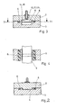
- a device 1 corresponding to the exemplary embodiment shown in FIGS. 1 to 4 consists of an upper part 2 and a lower part 3, between which a slot-shaped channel 4 for impregnating fiber strands or fiber ribbons 5 arranged next to one another is left free. While the sliver 5 to be impregnated is also shown in FIGS. 1 and 3, the latter is omitted in FIG. 2 in order to show the channel 4 better.
- the upper part 2 protrudes into the lower part 3 to seal the channel 4, furthermore both parts are sealed against one another and against the external pressure by sealing strips 6, for example made of rigid foam.
- Upper and lower parts 2 and 3 are connected by means of screws.
- a roller 8 is attached to the upper part 2, which; the sliver 5 presses a sealing strip 10 with the aid of a spring 9.
- the roller 8 with [3ichtological 10 are expediently made of hard elastic material, such as hard rubber.
- the roller 8 is mounted in slots arranged on the upper part 2 in elongated holes 12.
- a sealing strip 13 is arranged a short distance behind the entry of the sliver 5 into the channel 4, by means of which the channel 4 is sealed in the longitudinal direction against the external pressure.
- a chamber 14 At a sufficient distance from the inlet end of the channel 4 there is a chamber 14 which extends into both the upper part 2 and the lower part 3 and into which leads into a bore 15.
- Hose nipples 18 are screwed into both bores 15 and 17, to which hoses (not shown) can be attached.
- a vacuum pump is connected to the chamber 14 and synthetic resin under pressure is introduced into the chamber 16. Between the vacuum chamber 14 and the synthetic resin chamber 16 there is another chamber 21 into which a bore 22 leads. Gaseous reactive diluent is introduced through the bore 22 under pressure.
- the thinner thus serves as a barrier between the negative pressure in the chamber 14 and the pressurized resin in the chamber 16. Because the residual air quantity is flushed out through the gaseous thinner, a complete ventilation and impregnation of the sliver 5 is achieved.
- polyester resin for example, vaporous styrene serves as a reactive thinner.
- a sliver 5 is placed on the lower part in such a way that a little more extends beyond the lower part. Then the upper part 2 is put on with the roller 8 and tightened with the screws. If the hose nipples 18 are provided with the associated hoses, the sliver 5 can be impregnated by pulling in the direction of the arrow 18. The sliver 5 is vented in the chamber 14, then rinsed with reactive diluent in the chamber 21 and then soaked in the chamber 16 with synthetic resin.
- the negative pressure through the bore 15, the medium supply through the bores 17, 22 and the drawing speed in the direction of the arrow 18 can be controlled so that the resin film is always between the two chambers 16 and 21.
- the sliver 5 is always uniformly impregnated and at the same time prevents resin from entering the chambers 21 and 14.
- the resin film can be observed through a viewing window in the upper part 2 and the height of the negative pressure, the thinner and resin pressure and the drawing speed can accordingly be set manually.
- a light-optical regulation of the process parameters can thus take place, in which a light beam is passed through the viewing window, the refractive index of which indicates the impregnation state of the fiber sliver 5 and thus the boundary line of the resin return.
- the device 1 can also be used in a simpler form, e.g. for impregnating round fiber strands, be made from one piece, 4 round fiber openings being drilled into the device instead of the channel and the chambers being produced by lateral bores to be sealed.
- a simpler form e.g. for impregnating round fiber strands, be made from one piece, 4 round fiber openings being drilled into the device instead of the channel and the chambers being produced by lateral bores to be sealed.
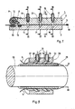
- FIGS. 5 to 7 show a tubular impregnation device 24, which consists of an inner tube 25 and an outer tube 26, which are pushed onto one another in a sealing manner and are connected to one another and sealed in a manner not shown.
- a number of slots or open bores 27 are arranged inside the tube 26, which expand to form chambers 28 and 29, which are connected to bores 30 and 31 which open into hose nipples 18.
- the chamber 28 is subjected to a negative pressure and the chamber 29 is filled with resin under pressure.
- the two fiber strands 5 shown are drawn through the slots 27 in the direction of the arrows 32 and can be wound onto a mandrel 33 immediately after impregnation.
- the representation of the further chamber arranged between the two chambers 28, 29 for supplying a reactive solvent according to FIG. 1 has been omitted. Sealing rings or other measures for sealing arranged between the two pipes 25 and 26 are also not shown. Of course there is also the possibility to provide viewing windows.
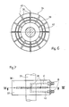
- the impregnation device 34 shown in FIGS. 6 and 7 permits the impregnation of a large number of rovings which are wound onto a winding mandrel 35.
- the impregnation device 34 which is pushed over the winding mandrel 35 and fastened in a manner not shown on a winding machine, consists of two assembled round plates 36 and 37, into which radial bores 38 are made for performing rovings, not shown. Between the outer and the inner diameter of the plates 36 and 37 channels 39 and 40 are screwed in, which are connected via holes 41 and 42 with hose nipples 18.
- the channel 39 is again subjected to a negative pressure and resin under pressure is passed into the channel 40, while the intermediate channel (also not shown) is charged with the reactive diluent.
- the rovings are introduced into the bores 38 in the direction of arrows 43, their fibers being vented in the channel 39 in the manner already described above, impregnated with resin in the channel 40 and in the intermediate position Not shown channel can be rinsed with reactive thinner.
Landscapes
- Engineering & Computer Science (AREA)
- Mechanical Engineering (AREA)
- Textile Engineering (AREA)
- Chemical & Material Sciences (AREA)
- Materials Engineering (AREA)
- Composite Materials (AREA)
- Treatment Of Fiber Materials (AREA)
- Moulding By Coating Moulds (AREA)
- Reinforced Plastic Materials (AREA)
Applications Claiming Priority (2)
| Application Number | Priority Date | Filing Date | Title |
|---|---|---|---|
| DE2949435 | 1979-12-08 | ||
| DE2949435 | 1979-12-08 |
Publications (2)
| Publication Number | Publication Date |
|---|---|
| EP0030264A1 EP0030264A1 (de) | 1981-06-17 |
| EP0030264B1 true EP0030264B1 (de) | 1984-06-13 |
Family
ID=6087929
Family Applications (1)
| Application Number | Title | Priority Date | Filing Date |
|---|---|---|---|
| EP80106428A Expired EP0030264B1 (de) | 1979-12-08 | 1980-10-22 | Verfahren zum Imprägnieren von Fasersträngen und Faserbändern |
Country Status (2)
| Country | Link |
|---|---|
| EP (1) | EP0030264B1 (OSRAM) |
| JP (1) | JPS5685458A (OSRAM) |
Families Citing this family (2)
| Publication number | Priority date | Publication date | Assignee | Title |
|---|---|---|---|---|
| JPH05220745A (ja) * | 1991-11-13 | 1993-08-31 | Monsanto Co | 繊維に樹脂を含浸させた複合材料の製造方法、その装置及び製造された複合材料 |
| EP2405047A1 (en) * | 2010-07-09 | 2012-01-11 | Siemens Aktiengesellschaft | Arrangement and method for wetting fibers with a fluid |
Family Cites Families (8)
| Publication number | Priority date | Publication date | Assignee | Title |
|---|---|---|---|---|
| US2348289A (en) * | 1943-01-19 | 1944-05-09 | Us Rubber Co | Application of liquid treating material to strip material |
| NL263041A (OSRAM) * | 1960-03-31 | 1900-01-01 | ||
| US3241343A (en) * | 1962-08-28 | 1966-03-22 | Yazawa Masahide | Apparatus for continuous high speed and uniform processing of fiber material |
| IL40966A (en) * | 1972-11-29 | 1976-07-30 | Klier S | A process for continuous treatment of textile materials |
| FR2214249A5 (OSRAM) * | 1973-01-15 | 1974-08-09 | Omnium Prospective Ind | |
| DE2320488A1 (de) * | 1973-04-21 | 1974-11-07 | Lutz & Ulmer | Vorrichtung zum behandeln von im wesentlichen eindimensionalem fasergut mit einer fluessigkeit |
| US4073974A (en) * | 1975-07-31 | 1978-02-14 | Bell Telephone Laboratories, Incorporated | Coating continuous filaments |
| GB1604620A (en) * | 1977-11-10 | 1981-12-09 | Britton A | Application of liquid material to webs |
-
1980
- 1980-10-22 EP EP80106428A patent/EP0030264B1/de not_active Expired
- 1980-11-04 JP JP15508680A patent/JPS5685458A/ja active Granted
Also Published As
| Publication number | Publication date |
|---|---|
| JPS5685458A (en) | 1981-07-11 |
| JPS6347820B2 (OSRAM) | 1988-09-26 |
| EP0030264A1 (de) | 1981-06-17 |
Similar Documents
| Publication | Publication Date | Title |
|---|---|---|
| DE69404708T2 (de) | Verfahren und Vorrichtung zur Herstellung eines Verbundgarnes | |
| DE3840035C2 (de) | Spleiss-Vorrichtung zum Verbinden von textilen Fäden bzw. Garnen mittels Druckluft, der eine Flüssigkeit beigemischt ist | |
| EP0255686B1 (de) | Verfahren zur Herstellung eines gefüllten optischen Übertragungselementes und Einrichtungen zur Durchführung des Verfahrens | |
| DE3521228A1 (de) | Verfahren und vorrichtung zur kontinuierlichen herstellung von halbzeug aus faserverstaerkten kunststoffen | |
| DD202189A5 (de) | Verfahren fuer die zufuehrung von fasern fuer die effektgarnherstellung und einrichtung fuer dessen verwirklichung | |
| DE4008640A1 (de) | Spleissvorrichtung zum verbinden von faeden | |
| DE3240485A1 (de) | Verfahren und vorrichtung zum spleissen eines gesponnenen fadens | |
| DE69321890T2 (de) | Verfahren zur Herstellung einer optischen Faser und Vorrichtung zur Durchführung dieses Verfahrens | |
| DE2817487A1 (de) | Verfahren zum einziehen eines fadens in eine texturierduese und vorrichtung zur durchfuehrung des verfahrens | |
| EP0030264B1 (de) | Verfahren zum Imprägnieren von Fasersträngen und Faserbändern | |
| EP0834392A2 (de) | Verfahren und Vorrichtung zum Herstellen eines Schlauchs zum Auskleiden von Rohrleitungen und Kanalsystemen | |
| EP0112934A1 (de) | Vorrichtung zum Herstellen von konischen Hohlmasten aus faserarmiertem Kunstharz | |
| DE69117526T2 (de) | Verfahren und vorrichtung zur herstellung von lichtpanelen | |
| DE2320642C3 (de) | Verfahren zur Behandlung eines Kabels aus Fasermaterial | |
| DE3305479A1 (de) | Verfahren und vorrichtung zum pneumatischen spleissen gesponnener faeden | |
| DE7934580U1 (de) | Vorrichtung zum impraegnieren von faserstraengen und faserbaendern | |
| DD284737A5 (de) | Verfahren und vorrichtung zum verlegen von kunststoffrohren | |
| DE102016219556A1 (de) | Vakuumeinrichtung für ein Pultrusionsverfahren, Verfahren zum Betrieb einer Vakuumeinrichtung in einem Pultrusionsverfahren und Verwendung der Vakuumeinrichtung | |
| EP0534895B1 (de) | Streckkammeranordnung | |
| DE2060261B2 (de) | Verfahren zum Herstellen eines Rohres aus faserverstärktem Kunststoff sowie Verfahren zur Durch führung des Verfahrens | |
| DE1504036A1 (de) | Verfahren zur Herstellung mindestens laengsgerichtete Verstaerkungseinlagen aufweisender Werkstuecke aus Kunststoffen | |
| DE19542096A1 (de) | Verfahren zum Anwickeln des vorlaufenden Endes einer quergetrennten Werkstoffbahn, insbes. einer quergetrennten Kunststoffbahn, auf eine Wickelhülse | |
| DE102023101604A1 (de) | Verfahren zum Verbinden von Towpregs und Wickelmaschine mit Verbindungsstation | |
| DE102020115541B4 (de) | Vorrichtung zur Herstellung von mit Matrixmaterial imprägnierten Faserrovingen | |
| DE2151430A1 (de) | Verfahren und Vorrichtung zum Beschichten von verstaerkten Schlaeuchen |
Legal Events
| Date | Code | Title | Description |
|---|---|---|---|
| PUAI | Public reference made under article 153(3) epc to a published international application that has entered the european phase |
Free format text: ORIGINAL CODE: 0009012 |
|
| AK | Designated contracting states |
Kind code of ref document: A1 Designated state(s): FR GB IT Designated state(s): FR GB IT |
|
| 17P | Request for examination filed |
Effective date: 19810417 |
|
| ITF | It: translation for a ep patent filed | ||
| GRAA | (expected) grant |
Free format text: ORIGINAL CODE: 0009210 |
|
| AK | Designated contracting states |
Kind code of ref document: B1 Designated state(s): FR GB IT Designated state(s): FR GB IT |
|
| ET | Fr: translation filed | ||
| PGFP | Annual fee paid to national office [announced via postgrant information from national office to epo] |
Ref country code: FR Payment date: 19840928 Year of fee payment: 5 |
|
| PLBE | No opposition filed within time limit |
Free format text: ORIGINAL CODE: 0009261 |
|
| STAA | Information on the status of an ep patent application or granted ep patent |
Free format text: STATUS: NO OPPOSITION FILED WITHIN TIME LIMIT |
|
| 26N | No opposition filed | ||
| GBPC | Gb: european patent ceased through non-payment of renewal fee | ||
| PG25 | Lapsed in a contracting state [announced via postgrant information from national office to epo] |
Ref country code: FR Free format text: LAPSE BECAUSE OF NON-PAYMENT OF DUE FEES Effective date: 19880630 |
|
| REG | Reference to a national code |
Ref country code: FR Ref legal event code: ST |
|
| PG25 | Lapsed in a contracting state [announced via postgrant information from national office to epo] |
Ref country code: GB Effective date: 19881118 |