EP0030264B1 - Method of impregnating rovings and slivers - Google Patents
Method of impregnating rovings and slivers Download PDFInfo
- Publication number
- EP0030264B1 EP0030264B1 EP80106428A EP80106428A EP0030264B1 EP 0030264 B1 EP0030264 B1 EP 0030264B1 EP 80106428 A EP80106428 A EP 80106428A EP 80106428 A EP80106428 A EP 80106428A EP 0030264 B1 EP0030264 B1 EP 0030264B1
- Authority
- EP
- European Patent Office
- Prior art keywords
- chamber
- fibre
- resin
- conducted
- bands
- Prior art date
- Legal status (The legal status is an assumption and is not a legal conclusion. Google has not performed a legal analysis and makes no representation as to the accuracy of the status listed.)
- Expired
Links
Images
Classifications
-
- B—PERFORMING OPERATIONS; TRANSPORTING
- B29—WORKING OF PLASTICS; WORKING OF SUBSTANCES IN A PLASTIC STATE IN GENERAL
- B29C—SHAPING OR JOINING OF PLASTICS; SHAPING OF MATERIAL IN A PLASTIC STATE, NOT OTHERWISE PROVIDED FOR; AFTER-TREATMENT OF THE SHAPED PRODUCTS, e.g. REPAIRING
- B29C70/00—Shaping composites, i.e. plastics material comprising reinforcements, fillers or preformed parts, e.g. inserts
- B29C70/04—Shaping composites, i.e. plastics material comprising reinforcements, fillers or preformed parts, e.g. inserts comprising reinforcements only, e.g. self-reinforcing plastics
- B29C70/28—Shaping operations therefor
- B29C70/40—Shaping or impregnating by compression not applied
- B29C70/50—Shaping or impregnating by compression not applied for producing articles of indefinite length, e.g. prepregs, sheet moulding compounds [SMC] or cross moulding compounds [XMC]
- B29C70/52—Pultrusion, i.e. forming and compressing by continuously pulling through a die
- B29C70/523—Pultrusion, i.e. forming and compressing by continuously pulling through a die and impregnating the reinforcement in the die
-
- B—PERFORMING OPERATIONS; TRANSPORTING
- B29—WORKING OF PLASTICS; WORKING OF SUBSTANCES IN A PLASTIC STATE IN GENERAL
- B29B—PREPARATION OR PRETREATMENT OF THE MATERIAL TO BE SHAPED; MAKING GRANULES OR PREFORMS; RECOVERY OF PLASTICS OR OTHER CONSTITUENTS OF WASTE MATERIAL CONTAINING PLASTICS
- B29B15/00—Pretreatment of the material to be shaped, not covered by groups B29B7/00 - B29B13/00
- B29B15/08—Pretreatment of the material to be shaped, not covered by groups B29B7/00 - B29B13/00 of reinforcements or fillers
- B29B15/10—Coating or impregnating independently of the moulding or shaping step
- B29B15/12—Coating or impregnating independently of the moulding or shaping step of reinforcements of indefinite length
- B29B15/122—Coating or impregnating independently of the moulding or shaping step of reinforcements of indefinite length with a matrix in liquid form, e.g. as melt, solution or latex
-
- D—TEXTILES; PAPER
- D06—TREATMENT OF TEXTILES OR THE LIKE; LAUNDERING; FLEXIBLE MATERIALS NOT OTHERWISE PROVIDED FOR
- D06B—TREATING TEXTILE MATERIALS USING LIQUIDS, GASES OR VAPOURS
- D06B21/00—Successive treatments of textile materials by liquids, gases or vapours
-
- D—TEXTILES; PAPER
- D06—TREATMENT OF TEXTILES OR THE LIKE; LAUNDERING; FLEXIBLE MATERIALS NOT OTHERWISE PROVIDED FOR
- D06B—TREATING TEXTILE MATERIALS USING LIQUIDS, GASES OR VAPOURS
- D06B3/00—Passing of textile materials through liquids, gases or vapours to effect treatment, e.g. washing, dyeing, bleaching, sizing, impregnating
- D06B3/04—Passing of textile materials through liquids, gases or vapours to effect treatment, e.g. washing, dyeing, bleaching, sizing, impregnating of yarns, threads or filaments
- D06B3/045—Passing of textile materials through liquids, gases or vapours to effect treatment, e.g. washing, dyeing, bleaching, sizing, impregnating of yarns, threads or filaments in a tube or a groove
Definitions
- the invention relates to a method according to the preamble of claim 1.
- the invention is therefore based on the object of carrying out a method according to the preamble of claim 1 in such a way that the air is removed from the fiber strands or ribbons with certainty and the impregnation process is technically perfectly controllable.
- the invention provides a method with which, depending on the negative pressure applied to the first chamber, an air-bubble-free fiber strand can be impregnated with the synthetic resin in the last chamber.
- the gaseous, reactive thinner in the third, middle chamber flushes out the residual air remaining from the vacuum chamber and the fiber strand is made absolutely air-free before soaking. In the last chamber, only a slight overpressure of a few bar is required to soak the fibers.
- the process parameters negative pressure, thinner and resin pressure and drawing speed of the fibers can be set so that the backflow rate consisting of the excess pressure of the resin is approximately the same as the rate at which the impregnated material is drawn off.
- light-optical control of the above-mentioned process parameters can be carried out with the aid of viewing windows arranged in front of the synthetic resin chamber. By means of the refractive index of a light beam guided through the viewing window, the boundary line of the resin return can be controlled properly.
- the method according to the invention can be used both for flat impregnation devices with fiber channels arranged next to one another for laminating essentially flat components and for round impregnation devices with radial fiber openings which are integrated directly with a winding machine.
- Both fiber strands and fiber tapes for immediate use for components made of fiber-reinforced plastic and prepregs for later use can be produced with the method according to the invention.
- the resin / fiber content can be adjusted according to the intended use with a previously unattainable accuracy.
- a device 1 corresponding to the exemplary embodiment shown in FIGS. 1 to 4 consists of an upper part 2 and a lower part 3, between which a slot-shaped channel 4 for impregnating fiber strands or fiber ribbons 5 arranged next to one another is left free. While the sliver 5 to be impregnated is also shown in FIGS. 1 and 3, the latter is omitted in FIG. 2 in order to show the channel 4 better.
- the upper part 2 protrudes into the lower part 3 to seal the channel 4, furthermore both parts are sealed against one another and against the external pressure by sealing strips 6, for example made of rigid foam.
- Upper and lower parts 2 and 3 are connected by means of screws.
- a roller 8 is attached to the upper part 2, which; the sliver 5 presses a sealing strip 10 with the aid of a spring 9.
- the roller 8 with [3ichtological 10 are expediently made of hard elastic material, such as hard rubber.
- the roller 8 is mounted in slots arranged on the upper part 2 in elongated holes 12.
- a sealing strip 13 is arranged a short distance behind the entry of the sliver 5 into the channel 4, by means of which the channel 4 is sealed in the longitudinal direction against the external pressure.
- a chamber 14 At a sufficient distance from the inlet end of the channel 4 there is a chamber 14 which extends into both the upper part 2 and the lower part 3 and into which leads into a bore 15.
- Hose nipples 18 are screwed into both bores 15 and 17, to which hoses (not shown) can be attached.
- a vacuum pump is connected to the chamber 14 and synthetic resin under pressure is introduced into the chamber 16. Between the vacuum chamber 14 and the synthetic resin chamber 16 there is another chamber 21 into which a bore 22 leads. Gaseous reactive diluent is introduced through the bore 22 under pressure.
- the thinner thus serves as a barrier between the negative pressure in the chamber 14 and the pressurized resin in the chamber 16. Because the residual air quantity is flushed out through the gaseous thinner, a complete ventilation and impregnation of the sliver 5 is achieved.
- polyester resin for example, vaporous styrene serves as a reactive thinner.
- a sliver 5 is placed on the lower part in such a way that a little more extends beyond the lower part. Then the upper part 2 is put on with the roller 8 and tightened with the screws. If the hose nipples 18 are provided with the associated hoses, the sliver 5 can be impregnated by pulling in the direction of the arrow 18. The sliver 5 is vented in the chamber 14, then rinsed with reactive diluent in the chamber 21 and then soaked in the chamber 16 with synthetic resin.
- the negative pressure through the bore 15, the medium supply through the bores 17, 22 and the drawing speed in the direction of the arrow 18 can be controlled so that the resin film is always between the two chambers 16 and 21.
- the sliver 5 is always uniformly impregnated and at the same time prevents resin from entering the chambers 21 and 14.
- the resin film can be observed through a viewing window in the upper part 2 and the height of the negative pressure, the thinner and resin pressure and the drawing speed can accordingly be set manually.
- a light-optical regulation of the process parameters can thus take place, in which a light beam is passed through the viewing window, the refractive index of which indicates the impregnation state of the fiber sliver 5 and thus the boundary line of the resin return.
- the device 1 can also be used in a simpler form, e.g. for impregnating round fiber strands, be made from one piece, 4 round fiber openings being drilled into the device instead of the channel and the chambers being produced by lateral bores to be sealed.
- a simpler form e.g. for impregnating round fiber strands, be made from one piece, 4 round fiber openings being drilled into the device instead of the channel and the chambers being produced by lateral bores to be sealed.
- FIGS. 5 to 7 show a tubular impregnation device 24, which consists of an inner tube 25 and an outer tube 26, which are pushed onto one another in a sealing manner and are connected to one another and sealed in a manner not shown.
- a number of slots or open bores 27 are arranged inside the tube 26, which expand to form chambers 28 and 29, which are connected to bores 30 and 31 which open into hose nipples 18.
- the chamber 28 is subjected to a negative pressure and the chamber 29 is filled with resin under pressure.
- the two fiber strands 5 shown are drawn through the slots 27 in the direction of the arrows 32 and can be wound onto a mandrel 33 immediately after impregnation.
- the representation of the further chamber arranged between the two chambers 28, 29 for supplying a reactive solvent according to FIG. 1 has been omitted. Sealing rings or other measures for sealing arranged between the two pipes 25 and 26 are also not shown. Of course there is also the possibility to provide viewing windows.
- the impregnation device 34 shown in FIGS. 6 and 7 permits the impregnation of a large number of rovings which are wound onto a winding mandrel 35.
- the impregnation device 34 which is pushed over the winding mandrel 35 and fastened in a manner not shown on a winding machine, consists of two assembled round plates 36 and 37, into which radial bores 38 are made for performing rovings, not shown. Between the outer and the inner diameter of the plates 36 and 37 channels 39 and 40 are screwed in, which are connected via holes 41 and 42 with hose nipples 18.
- the channel 39 is again subjected to a negative pressure and resin under pressure is passed into the channel 40, while the intermediate channel (also not shown) is charged with the reactive diluent.
- the rovings are introduced into the bores 38 in the direction of arrows 43, their fibers being vented in the channel 39 in the manner already described above, impregnated with resin in the channel 40 and in the intermediate position Not shown channel can be rinsed with reactive thinner.
Description
Die Erfindung bezieht sich auf ein Verfahren nach dem Oberbegriff des Anspruchs 1.The invention relates to a method according to the preamble of claim 1.
Ein solches Verfahren ist bereits durch die US-A-3 905 327 bekannt. Bei diesem Verfahren werden die Faserstränge zunächst durch eine Unterdruckzone geführt und dann in einer anschließenden Kunstharzkammer mit unter Druck stehendem Kunstharz getränkt. Dieses Verfahren weist den Nachteil auf, daß die Fasern beim Durchlaufen der Unterdruckzone nicht völlig von Lufteinschlüssen befreit werden können und diese dann unter der Druckeinwirkung des Kunstharzes in der Kunstharzkammer als Luftbläschen in den Fasern verbleiben und verdichtet werden. Beim Druchgang durch eine weitere, an die Kunstharzkammer anschließende Unterdruckzone ist es dann nicht möglich, die in den getränkten Fasern verbliebenen Luftbläschen zu entfernen.Such a method is already known from US-A-3 905 327. In this method, the fiber strands are first passed through a vacuum zone and then soaked in a subsequent resin chamber with resin under pressure. This method has the disadvantage that the fibers cannot be completely freed of air inclusions when passing through the vacuum zone and these then remain under the pressure of the synthetic resin in the synthetic resin chamber as air bubbles in the fibers and are compressed. When passing through a further vacuum zone adjoining the synthetic resin chamber, it is then not possible to remove the air bubbles remaining in the impregnated fibers.
Der Erfindung liegt deshalb die Aufgabe zugrunde, ein Verfahren nach dem Oberbegriff des Anspruchs 1 so auszuführen, daß mit Sicherheit die Luft aus den Fasersträngen oderbändern entfernt wird und der Imprägniervorgang technisch einwandfrei beherrschbar ist.The invention is therefore based on the object of carrying out a method according to the preamble of claim 1 in such a way that the air is removed from the fiber strands or ribbons with certainty and the impregnation process is technically perfectly controllable.
Die Lösung dieser Aufgabe erfolgt mit einem Verfahren entsprechend den Merkmalen des kennzeichnenden Teils des Anspruchs 1.This object is achieved with a method according to the features of the characterizing part of claim 1.
Vorteilhafte Ausbildungen der Erfindung sind in den Unteransprüchen wiedergegeben.Advantageous embodiments of the invention are given in the subclaims.
Die Erfindung schafft ein Verfahren, mit dem mit Sicherheit je nach dem an die erste Kammer angelegten Unterdruck ein luftblasenfreier Faserstrang in der letzten Kammer mit dem Kunstharz getränkt werden kann. Dabei wird durch den gasförmigen, reaktiven Verdünner in der dritten, mittleren Kammer die von der Unterdruckkammer verbliebene Restluftmenge herausgespült und der Faserstrang vor dem Tränken absolut luftfrei gemacht. In der letzten Kammer ist dann nur ein geringer Überdruck von wenigen bar zum Tränken der Fasern erforderlich.The invention provides a method with which, depending on the negative pressure applied to the first chamber, an air-bubble-free fiber strand can be impregnated with the synthetic resin in the last chamber. The gaseous, reactive thinner in the third, middle chamber flushes out the residual air remaining from the vacuum chamber and the fiber strand is made absolutely air-free before soaking. In the last chamber, only a slight overpressure of a few bar is required to soak the fibers.
Beim erfindungsgemäßen Imprägnieren können die Verfahrens-parameter Unterdruck, Verdünner-und Harzdruck und Ziehgeschwindigkeit der Fasern so eingestellt werden, daß die aus dem Überdruck des Harzes bestehende Rückstromgeschwindig-in etwa gleich ist der Abzugsgeschwindigkeit des Tränkgutes. Zur Unterst ützung einer kontinuierlichen und einwandfreien Tränkung kann mit Hilfe von vor der Kunstharzkammer angeordneten Sichtfenstern eine lichtoptische Regelung der oben angeführten Verfahrensparameter erfolgen. Mittels des Brechungsindexes eines durch die Sichtfenster geführten Lichtstrahles ist die Grenzlinie des Harzrücklaufes einwandfrei zu steuern.In the impregnation according to the invention, the process parameters negative pressure, thinner and resin pressure and drawing speed of the fibers can be set so that the backflow rate consisting of the excess pressure of the resin is approximately the same as the rate at which the impregnated material is drawn off. In order to support continuous and perfect impregnation, light-optical control of the above-mentioned process parameters can be carried out with the aid of viewing windows arranged in front of the synthetic resin chamber. By means of the refractive index of a light beam guided through the viewing window, the boundary line of the resin return can be controlled properly.
Das erfindungsgemäße Verfahren ist anwendbar sowohl für flache Imprägniervorrichtungen mit nebeneinander angeordneten Faserkanälen zum Laminieren von im wesentlichen flachen Bauteilen als auch für runde Imprägniervorrichtungen mit radialen Faseröffnungen, die direkt mit einer Wickelmaschine integriert werden.The method according to the invention can be used both for flat impregnation devices with fiber channels arranged next to one another for laminating essentially flat components and for round impregnation devices with radial fiber openings which are integrated directly with a winding machine.
Es können mit dem erfindungsgemäßen Verfahren sowohl Faserstränge und Faserbänder zur sofortigen Verwendung für Bauteile aus faserverstärktem Kunststoff als auch Prepregs zur späteren Verwendung hergestellt werden. Durch die Einstellung der Verfahrensparameter kann der Harz/Faseranteil in bisher kaum erreichbarer Genauigkeit dem Verwendungszweck entsprechend eingestellt werden.Both fiber strands and fiber tapes for immediate use for components made of fiber-reinforced plastic and prepregs for later use can be produced with the method according to the invention. By setting the process parameters, the resin / fiber content can be adjusted according to the intended use with a previously unattainable accuracy.
Weitere Vorteile der Erfindung ergeben sich aus der nachfolgenden Beschreibung von Ausführungsbeispielen der Erfindung anhand der Zeichnung. Es zeigen:
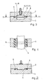
- Fig. 1 einen Schnitt durch eine erste Ausführungsform einer Imprägniervorrichtung;
- Fig. 2 einen Schnitt quer durch die Vorrichtung längs der Linie 11-11 der Fig. 1;
- Fig. 3 einen Schnitt quer durch in der Vorrichtung befindliche Kammern entsprechend den Linien 111-111 der Fig. 1;
- Fig. 4 einen Schnitt längs der Linie IV-IV der Fig. 3 mit der Draufsicht auf eine Kammer;
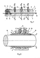
- Fig. 5 einen Schnitt durch eine Ausführungsform einer Imprägniervorrichtung, die um eine Welle herumgeführt ist, und
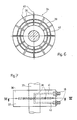
- Fign. 6 und 7 im Querschnitt bzw. in der Draufsicht eine weitere Ausführungsform einer um eine Welle herumgeführten Imprägniervorrichtung.
- 1 shows a section through a first embodiment of an impregnation device.
- 2 shows a section across the device along the line 11-11 of Fig. 1.
- 3 shows a section transversely through chambers located in the device according to lines 111-111 of FIG. 1;
- Fig. 4 is a section along the line IV-IV of Figure 3 with a plan view of a chamber.
- 5 shows a section through an embodiment of an impregnation device which is guided around a shaft, and
- Fig. 6 and 7 in cross section and in plan view a further embodiment of an impregnation device guided around a shaft.
Eine Vorrichtung 1 entsprechend dem in den Fig. 1 bis 4 gezeigten Ausführungsbeispiel besteht aus einem Oberteil 2 und einem Unterteil 3, zwischen denen ein schlitzförmiger Kanal 4 zum Imprägnieren von nebeneinander angeordneten Fasersträngen oder Faserbändern 5 freigelassen ist. Während in den Fig. 1 und 3 das zu tränkende Faserband 5 mit dargestellt ist, ist letzteres in der Fig. 2 fortgelassen, um den Kanal 4 besser zu zeigen. Das Oberteil 2 ragt zur Abdichtung des Kanals 4 in das Unterteil 3 hinein, weiterhin sind beide Teile durch Dichtleisten 6, z.B. aus Hartschaum, gegeneinander und gegen den Außendruck abgedichtet. Ober-und Unterteil 2 und 3 sind mittels Schrauben verbunden. Zur Glättung des Faserbandes 5 vor dem Einführen in den Kanal 4 ist am Oberteil 2 eine Walze 8 angesetzt, welche; das Faserband 5 mit Hilfe einer Feder 9 auf eine Dichtleiste 10 drückt. Die Walze 8 mit [3ichtleiste 10 sind zweckmäßig aus hartelastischem Material, z.B. Hartgummi. Die Walze 8 ist in am Oberteil 2 angeordneten Laschen in Langlöchern 12 gelagert. Im Unterteil 3 ist ein kurzes Stück hinter dem Eintritt des Faserbandes 5 in den Kanal 4 eine Dichtleiste 13 angeordnet, durch die der Kanal 4 in der Längsrichtung gegenüber dem Außendruck abgedichtet ist. In einem ausreichenden Abstand vom Eintrittsende des Kanals 4 befindet sich eine Kammer 14, die sich sowohl in das Oberteil 2 als auch in das Unterteil 3 erstreckt und in die eine Bohrung 15 hineinführt. In einiger Entfernung von der Kammer 14 ist eine weitere Kammer 16 angeordnet, in die ebenfalls eine Bohrung 17 hineinführt. In beide Bohrungen 15 und 17 sind Schlauchnippel 18 eingeschraubt, an die nicht dargestellte Schläuche angesetzt werden können. An die Kammer wird 14 wird eine Vakuumpumpe angeschlossen und in die Kammer 16 wird unter Druck stehendes Kunstharz eingeleitet. Zwischen der Unterdruckkammer 14 und der Kunstharzkammer 16 befindet sich eine weitere Kammer 21, in die eine Bohrung 22 hineinführt. Durch die Bohrung 22 wird gasförmiger reaktiver Verdünner unter Druck eingebracht. Der Verdünner dient dadurch als Sperre zwischen dem Unterdruck in der Kammer 14 und dem unter Druck stehenden Harz in der Kammer 16. Dadurch, daß die Restluftmenge durch den gasförmigen Verdünner ausgespült wird, wird eine vollständige Entlüftung und Durchtränkung des Faserbandes 5 erzielt. Bei der Verwendung von z.B. Polyesterharz dient dampfförmiges Styrol als reaktiver Verdünner.A device 1 corresponding to the exemplary embodiment shown in FIGS. 1 to 4 consists of an
Nachfolgend soll die Funktionsweise der Vorrichtung 1 beschrieben werden. Ein Faserband 5 wird bei abgenommenem Oberteil 2 auf das Unterteil so aufgelegt, daß noch ein Stück das Unterteil überragt. Dann wird das Oberteil 2 mit der Walze 8 aufgesetzt und mit den Schrauben festgezogen. Wenn die Schlauchnippel 18 mit den zugehörigen Schläuchen versehen sind, kann das Faserband 5 durch Ziehen in Richtung des Pfeiles 18 imprägniert werden. Dabei wird das Faserband 5 in der Kammer 14 entlüftet, dann mit reaktivem Verdünner in der Kammer 21 durchspült und nachher in der Kammer 16 mit Kunstharz getränkt. Der Unterdruck durch die Bohrung 15, die Mediumzufuhr durch die Bohrungen 17, 22 und die Ziehgeschwindigkeit in Richtung des Pfeiles 18 können so geregelt werden, daß sich der Harzfilm stets zwischen den beiden Kammern 16 und 21 befindet. Dadurch wird eine stets gleichmäßige Tränkung des Faserbandes 5 erreicht und gleichzeitig vermieden, daß Harz in die Kammern 21 und 14 eintritt. Die Beobachtung des Harzfilmes kann durch ein Sichtfenster im Oberteil 2 erfolgen und dementsprechend die Höhe des Unterdruckes, des Verdünner-und Harzdruckes und der Ziehgeschwindigkeit manuell eingestellt werden. Es ist jedoch zur Erzielung einer hohen Imprägniergeschwindigkeit rationeller, auch im Unterteil ein Sichtfenster einzubauen. Damit kann eine lichtoptische Regelung der Verfahrensparameter erfolgen, bei der durch die Sichtfenster ein Lichtstrahl hindurchgeleitet wird, dessen Brechungsindex den Tränkungszustand des Faserbandes 5 und damit die Grenzlinie des Harzrücklaufes anzeigt.The mode of operation of the device 1 will be described below. When the
Die Vorrichtung 1 kann auch in einfacherer Form, z.B. zum Tränken von runden Fasersträngen, aus einem Stück hergestellt werden, wobei anstelle des Kanals 4 runde Faseröffnungen in die Vorrichtung eingebohrt werden und die Kammern durch seitlich abzudichtende Querbohrungen erzeugt werden. Andererseits besteht auch die Möglichkeit, mehrere Kanäle oder Öffnungen in einer einzigen Vorrichtung anzuordnen, um dadurch verschiedenartige Faserstränge oder Faserbänder gleichzeitig imprägnieren zu können.The device 1 can also be used in a simpler form, e.g. for impregnating round fiber strands, be made from one piece, 4 round fiber openings being drilled into the device instead of the channel and the chambers being produced by lateral bores to be sealed. On the other hand, there is also the possibility of arranging several channels or openings in a single device in order to be able to simultaneously impregnate different types of fiber strands or fiber tapes.
Andere Ausführungsformen der Imprägniervorrichtung sind in den Fign. 5 bis 7 schematisch dargestellt. In der Fig. 5 ist eine rohrförmige Imprägniervorrichtung 24 gezeigt, die aus einem inneren Rohr 25 und einem aüßeren Rohr 26 besteht, die dichtend aufeinander geschoben werden und in nicht dargestellter Weise miteinander verbunden und abgedichtet sind. Innerhalb des Rohres 26 sind am Umfang verteilt eine Anzahl von Schlitzen oder offenen Bohrungen 27 angeordnet, die sich zu Kammern 28 und 29 erweitern, die mit Bohrungen 30 und 31 verbunden sind, welche in Schlauchnippel 18 einmünden. Entsprechend dem vorstehend gezeigten Ausführungsbeispiel ist die Kammer 28 einem Unterdruck ausgesetzt, und die Kammer 29 ist mit unter Druck stehendem Harz gefüllt. Die beiden dargestellten Faserstränge 5 werden in Richtung der Pfeile 32 durch die Schlitze 27 gezogen und können unmittelbar nach dem Imprägnieren auf einen Wickeldorn 33 gewickelt werden. Bei dieser Figur wurde auf die Darstellung der zwischen den beiden Kammern 28, 29 angeordneten, weiteren Kammer zur Zuführung eines reaktiven Lösungsmittels entsprechend Fig. 1 verzichtet. Zwischen den beiden Rohren 25 und 26 angeordnete Dichtungsringe oder sonstige Maßnahmen zur Abdichtung sind ebenfalls nicht dargestellt. Es besteht selbstverständlich auch die Möglichkeit, Sichtfenster vorzusehen.Other embodiments of the impregnation device are shown in FIGS. 5 to 7 shown schematically. 5 shows a
Die in den Fign. 6 und 7 dargestellte Imprägniervorrichtung 34 gestattet das Imprägnieren von einer großen Anzahl von Rovings, die auf einen Wickeldorn 35 aufgewickelt werden. Die Imprägniervorrichtung 34, die über den Wickeldorn 35 geschoben und in nicht dargestellter Weise auf einer Wickelmaschine befestigt wird, besteht aus zwei zusammengesetzten runden Platten 36 und 37, in die radiale Bohrungen 38 zum Durchführen von nicht dargestellten Rovings eingebracht sind. Zwischen dem äußeren und dem inneren Durchmesser der Platten 36 und 37 sind Kanäle 39 und 40 eingedreht, die über Bohrungen 41 und 42 mit Schlauchnippeln 18 verbunden sind. Der Kanal 39 ist wiederum einem Unterdruck ausgesetzt und in den Kanal 40 wird unter Druck stehendes Harz geleitet, während der dazwischen liegende Kanal (ebenfalls nicht dargestellt) mit dem reaktiven Verdünner beschickt wird. Die Rovings werden in Richtung von Pfeilen 43 in die Bohrungen 38 eingeführt, wobei ihre Fasern in bereits vorstehend beschriebener Weise im Kanal 39 entlüftet, im Kanal 40 mit Harz getränkt und in dem dazwischen liegenden, nicht dargestellten Kanal mit reaktivem Verdünner bespült werden.The in Figs. The
Claims (7)
Applications Claiming Priority (2)
| Application Number | Priority Date | Filing Date | Title |
|---|---|---|---|
| DE2949435 | 1979-12-08 | ||
| DE2949435 | 1979-12-08 |
Publications (2)
| Publication Number | Publication Date |
|---|---|
| EP0030264A1 EP0030264A1 (en) | 1981-06-17 |
| EP0030264B1 true EP0030264B1 (en) | 1984-06-13 |
Family
ID=6087929
Family Applications (1)
| Application Number | Title | Priority Date | Filing Date |
|---|---|---|---|
| EP80106428A Expired EP0030264B1 (en) | 1979-12-08 | 1980-10-22 | Method of impregnating rovings and slivers |
Country Status (2)
| Country | Link |
|---|---|
| EP (1) | EP0030264B1 (en) |
| JP (1) | JPS5685458A (en) |
Families Citing this family (2)
| Publication number | Priority date | Publication date | Assignee | Title |
|---|---|---|---|---|
| EP0542709A1 (en) * | 1991-11-13 | 1993-05-19 | Monsanto Company | Method and apparatus for making composite materials |
| EP2405047A1 (en) * | 2010-07-09 | 2012-01-11 | Siemens Aktiengesellschaft | Arrangement and method for wetting fibers with a fluid |
Family Cites Families (8)
| Publication number | Priority date | Publication date | Assignee | Title |
|---|---|---|---|---|
| US2348289A (en) * | 1943-01-19 | 1944-05-09 | Us Rubber Co | Application of liquid treating material to strip material |
| NL263041A (en) * | 1960-03-31 | 1900-01-01 | ||
| US3241343A (en) * | 1962-08-28 | 1966-03-22 | Yazawa Masahide | Apparatus for continuous high speed and uniform processing of fiber material |
| IL40966A (en) * | 1972-11-29 | 1976-07-30 | Klier S | Process for continuous treatment of textile materials |
| FR2214249A5 (en) * | 1973-01-15 | 1974-08-09 | Omnium Prospective Ind | |
| DE2320488A1 (en) * | 1973-04-21 | 1974-11-07 | Lutz & Ulmer | DEVICE FOR TREATMENT OF SUBSTANTIALLY ONE-DIMENSIONAL FIBER MATERIAL WITH A LIQUID |
| US4073974A (en) * | 1975-07-31 | 1978-02-14 | Bell Telephone Laboratories, Incorporated | Coating continuous filaments |
| GB1604620A (en) * | 1977-11-10 | 1981-12-09 | Britton A | Application of liquid material to webs |
-
1980
- 1980-10-22 EP EP80106428A patent/EP0030264B1/en not_active Expired
- 1980-11-04 JP JP15508680A patent/JPS5685458A/en active Granted
Also Published As
| Publication number | Publication date |
|---|---|
| JPS6347820B2 (en) | 1988-09-26 |
| JPS5685458A (en) | 1981-07-11 |
| EP0030264A1 (en) | 1981-06-17 |
Similar Documents
| Publication | Publication Date | Title |
|---|---|---|
| EP0206134B1 (en) | Method and apparatus for continuously producing fibre-reinforced plastic semi-products | |
| DE3835575A1 (en) | COMPOSITES | |
| DE3840035C2 (en) | Splicing device for connecting textile threads or yarns using compressed air to which a liquid is added | |
| EP0255686B1 (en) | Method for producing a filled optical transmission element, and device for performing said method | |
| WO2018036790A1 (en) | Device and method for impregnating fiber structures | |
| DD202189A5 (en) | PROCESS FOR THE FEEDING OF FIBERS FOR EFFECTIVE YARN MANUFACTURE AND ESTABLISHMENT FOR THEIR IMPROVEMENT | |
| DE4008640A1 (en) | SPLITTING DEVICE FOR CONNECTING THREADS | |
| DE1704710A1 (en) | Method and device for the production of objects consisting of wound threads | |
| DE3240485A1 (en) | METHOD AND DEVICE FOR SPLITING A SPUNNED THREAD | |
| DE2817487A1 (en) | METHOD FOR DRAWING A THREAD INTO A TEXTURING NOZZLE AND DEVICE FOR CARRYING OUT THE METHOD | |
| EP0030264B1 (en) | Method of impregnating rovings and slivers | |
| EP0834392A2 (en) | Method and apparatus for manufacturing a hose for lining of pipelines and channel systems | |
| EP0112934A1 (en) | Apparatus for making tapered hollow poles of fibre-reinforced resin | |
| DE3305479A1 (en) | METHOD AND DEVICE FOR PNEUMATIC SPLICING OF SPONNED THREADS | |
| DE2320642C3 (en) | Method for treating a cable made of fiber material | |
| DE7934580U1 (en) | DEVICE FOR IMPREGNATING FIBER STRINGS AND TAPES | |
| DD284737A5 (en) | METHOD AND DEVICE FOR LAYING PLASTIC PIPES | |
| EP0344650B1 (en) | Method for making an inorganic multifilament yarn | |
| EP0534895B1 (en) | Stretching chamber | |
| DE2060261B2 (en) | Process for producing a pipe made of fiber-reinforced plastic and process for carrying out the process | |
| DE1504036A1 (en) | Process for the production of workpieces made of plastics with at least longitudinal reinforcement inserts | |
| DE602004005032T2 (en) | METHOD AND ARRANGEMENT IN COATING STRIP FOR FIBER-FORMED PRODUCT OR FIBER-MOLDED PRODUCTS | |
| DE19542096A1 (en) | Continuous winding of film web material | |
| DE102020115541B4 (en) | Device for producing fiber rovings impregnated with matrix material | |
| DE3344990A1 (en) | Device for winding components |
Legal Events
| Date | Code | Title | Description |
|---|---|---|---|
| PUAI | Public reference made under article 153(3) epc to a published international application that has entered the european phase |
Free format text: ORIGINAL CODE: 0009012 |
|
| AK | Designated contracting states |
Kind code of ref document: A1 Designated state(s): FR GB IT Designated state(s): FR GB IT |
|
| 17P | Request for examination filed |
Effective date: 19810417 |
|
| ITF | It: translation for a ep patent filed |
Owner name: STUDIO JAUMANN |
|
| GRAA | (expected) grant |
Free format text: ORIGINAL CODE: 0009210 |
|
| AK | Designated contracting states |
Kind code of ref document: B1 Designated state(s): FR GB IT Designated state(s): FR GB IT |
|
| ET | Fr: translation filed | ||
| PGFP | Annual fee paid to national office [announced via postgrant information from national office to epo] |
Ref country code: FR Payment date: 19840928 Year of fee payment: 5 |
|
| PLBE | No opposition filed within time limit |
Free format text: ORIGINAL CODE: 0009261 |
|
| STAA | Information on the status of an ep patent application or granted ep patent |
Free format text: STATUS: NO OPPOSITION FILED WITHIN TIME LIMIT |
|
| 26N | No opposition filed | ||
| GBPC | Gb: european patent ceased through non-payment of renewal fee | ||
| PG25 | Lapsed in a contracting state [announced via postgrant information from national office to epo] |
Ref country code: FR Free format text: LAPSE BECAUSE OF NON-PAYMENT OF DUE FEES Effective date: 19880630 |
|
| REG | Reference to a national code |
Ref country code: FR Ref legal event code: ST |
|
| PG25 | Lapsed in a contracting state [announced via postgrant information from national office to epo] |
Ref country code: GB Effective date: 19881118 |