EP0028733B1 - Rolladen, Verfahren zur Herstellung desselben und Hohlprofilstab für Rolladen - Google Patents
Rolladen, Verfahren zur Herstellung desselben und Hohlprofilstab für Rolladen Download PDFInfo
- Publication number
- EP0028733B1 EP0028733B1 EP19800106425 EP80106425A EP0028733B1 EP 0028733 B1 EP0028733 B1 EP 0028733B1 EP 19800106425 EP19800106425 EP 19800106425 EP 80106425 A EP80106425 A EP 80106425A EP 0028733 B1 EP0028733 B1 EP 0028733B1
- Authority
- EP
- European Patent Office
- Prior art keywords
- hollow profile
- apertures
- hook
- rod
- rods
- Prior art date
- Legal status (The legal status is an assumption and is not a legal conclusion. Google has not performed a legal analysis and makes no representation as to the accuracy of the status listed.)
- Expired
Links
- 238000004519 manufacturing process Methods 0.000 title claims description 7
- 238000000034 method Methods 0.000 title claims description 6
- 230000005489 elastic deformation Effects 0.000 claims description 4
- 230000035515 penetration Effects 0.000 claims 1
- 238000013459 approach Methods 0.000 description 3
- 238000005452 bending Methods 0.000 description 3
- 238000004873 anchoring Methods 0.000 description 2
- 238000006073 displacement reaction Methods 0.000 description 2
- 238000003780 insertion Methods 0.000 description 2
- 230000037431 insertion Effects 0.000 description 2
- 230000001154 acute effect Effects 0.000 description 1
- 238000005520 cutting process Methods 0.000 description 1
- 238000001125 extrusion Methods 0.000 description 1
- 238000005304 joining Methods 0.000 description 1
- 238000003801 milling Methods 0.000 description 1
- 230000008439 repair process Effects 0.000 description 1
- 230000000284 resting effect Effects 0.000 description 1
Images

Classifications
-
- E—FIXED CONSTRUCTIONS
- E06—DOORS, WINDOWS, SHUTTERS, OR ROLLER BLINDS IN GENERAL; LADDERS
- E06B—FIXED OR MOVABLE CLOSURES FOR OPENINGS IN BUILDINGS, VEHICLES, FENCES OR LIKE ENCLOSURES IN GENERAL, e.g. DOORS, WINDOWS, BLINDS, GATES
- E06B9/00—Screening or protective devices for wall or similar openings, with or without operating or securing mechanisms; Closures of similar construction
- E06B9/02—Shutters, movable grilles, or other safety closing devices, e.g. against burglary
- E06B9/08—Roll-type closures
- E06B9/11—Roller shutters
- E06B9/15—Roller shutters with closing members formed of slats or the like
- E06B9/165—Roller shutters with closing members formed of slats or the like with slats disappearing in each other; with slats the distance between which can be altered
Definitions
- the invention relates to a roller shutter according to the preamble of claim 1. Furthermore, the invention relates to a method for producing the same and a hollow profile bar for roller shutters.
- a roller shutter, a method for its production and a hollow profile rod for roller shutters of the type specified in the preamble of claims 1, 5 and 8 have been proposed in DE-B-1 253 897, first to facilitate the assembly of the roller shutter hollow profile rods and to solve the problems secondly, to prevent mutual displacement of the rods without the need for frontal transverse plates covering the articulation points to be attached to every second hollow profile rod of the roller shutter after the rods have been joined together.
- this document proposes to provide a longitudinal gap instead of the longitudinal gap which is common in the prior art at the time and which is continuous from one rod end to the other and is open at both ends and is closed at its ends by transverse webs which cause a displacement prevent the connecting tab protruding through this gap.
- the object is achieved to create a roller shutter of this type, the hollow profile bars can be assembled faster and move safely with a less complex procedure.
- the hollow profile bars of the roller shutter according to the invention can be attached to one another in a simple, non-displaceable manner. You can place all the hollow profile bars for a roller shutter to be manufactured side by side and simply collide them all at the same time. Their production is no more complex than that of the hollow profile bars of the known roller shutter. Taking advantage of the resilient flexibility of the wider profile walls, they can also be detached from each other more easily and quickly, and can therefore be replaced on site in the event of repairs.
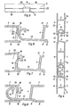
- the part of a roller shutter shown in FIGS. 1, 2, 4 and 5 comprises five hollow profile bars 1a to 1e, of which the bar 1b hangs on the bar 1a and stands on the bars lc, 1d and 1e standing one above the other.
- the rods are identical to one another and, as shown in FIGS. 2 and 4, have a flat, square cavity profile with two narrow longitudinal sides 4 and 5, two wider longitudinal sides 6 and 7 and two webs 2 and 3 used for stiffening.
- the upper and the lower the narrower longitudinal sides 4 and 5 run at an oblique angle to the wider longitudinal sides 6 and 7.
- the side 5 has two elongated holes 9 and the side 6 a projection 10 projecting beyond the side 5.
- This projection 10 is assigned a step 11 on the adjacent edge 12 of the adjacent rod.
- the projection 10 engages in this step 11 when the rods abut one another in an aligned position (rods 1b and 1c in FIGS. 2 and 4).
- the bars are in the direction of their thickness through the Approach 10, the level 11 and due to the inclination of pages 4 and 5 with respect to each other.
- each rod has two lugs 13, 14, 15 protruding on the side 4.
- Each lug 13, 14, 15 engages through one of the elongated holes 9 on the adjacent side 5 of the adjacent rod and has a hook shape in the plane of the rod cross section curved end 14 with an inward projection 15, which is supported in the acute-angled corner 16 between the side 7 and the side 5 on the latter when the rods hang together (rods 1a and 1b in Fig. 2 and 4).
- the lugs 13, 14, 15 are adapted to the elongated holes 9 in the longitudinal direction of the rods, as a result of which the rods are fixed in relation to one another in the direction of their length.
- the lugs 13, 14, 15 are shaped, as described below with reference to FIG. 3, in such a way that their hook-shaped curved ends 14, 15 can only be hooked into the elongated holes 9 if the rods form an angle with one another, which is smaller than the smallest angle that occurs when the roller shutter is rolled up, and that the hook-shaped curved ends 14, 15 cannot unhook if the bars enclose a larger angle.
- the sides 7 of the adjacent bars enclose an acute angle a.
- the circular arc 19 touching the inner end of the projection 15 with the edge 18 as the center runs in the elongated hole 9 closely next to its (closer) longitudinal edge 20.
- the circular arc 21 with the edge 18 as the center touches the hook-shaped attachment end 14 on the outside in front of the surface 22 of the projection 10 facing the slot 9.
- the outer width (the semicircular diameter) of the hook-shaped extension 14, 15 is greater than the width of the elongated hole 9, so that the extension 13, 14, 15 cannot unhook from the elongated hole 9, unless the rods are in the in Fig 3 shown mutual situation that they never take in use.
- the possibility of detaching the rods from one another in this position in a corresponding manner saves time when the roller shutter is dismantled.
- the hook-shaped attachment end is semicircular, its outer radius can also be dimensioned slightly smaller than the slot width, in which case the hook-shaped attachment end can be pushed into the slot and pulled out when the rods are approximately at right angles to one another.
- the slot width is approximately half the width of side 5.
- each rod provided with the elongated holes 9 is immediately slotted continuously along the elongated holes 9, i. H. slots 25 extend from one elongated hole 9 to the other and from the outer elongated holes to the rod ends, so that the side 5 consists of two parts which are not connected but are separated from one another by the elongated holes 9 and the slots 25.
- the width of the slots 25 is substantially smaller than the width of the elongated holes 9.
- the slots 25 open into the elongated holes 9 at their (closer) longitudinal edge 20 facing the side 7. This ensures that the lugs 13 are attached to each other and with bars standing one on top of the other, have the greatest possible distance from the slots 25 and can in no way get into them. This must be avoided so that adjacent bars cannot move against each other in their longitudinal direction. This is additionally prevented by the fact that the slot width is much smaller than the thickness of the lugs.
- predetermined breaking points 25a can be provided which, as explained further below, are broken or cut through before the rods are joined together or broken when the rods collide (FIGS. 5 to 8).
- the wall thickness of one or both sides 6 and 7, preferably the side 7, is dimensioned in the area between the web 2 and the side 5 such that these wall parts give way (spread) when the hook-shaped attachment ends 14 are pushed into the elongated holes 9, 6 to 8 show.
- those in the rod cross-sectional plane are tapered in the direction away from the side 4 in the area in which they slide on the longitudinal edges of the elongated holes 9 during insertion.
- the taper is formed by the circular arc sections located in this area.
- the approach ends can also have another shape that is tapered in this sense, e.g. B. be approximately V-shaped.
- the rods can be arranged between two plates or between several strips, lateral guide strips for the rod ends also being able to be provided.
- the rods can also be held displaceably at their ends in two U-shaped strips.
- the distance between the plates or strips or the distance between the two U-legs of each of the two profile strips is to be selected such that the profile rod wall parts between the web 2 and the side 5 yield elastically as mentioned when the hook-shaped attachment ends 14 are inserted into the elongated holes 25 ( spread).
- the joint is exerted by means of a bar extending over the entire length of the rod or of such a jaw.
- the abutment and the butt cheek suitably have recesses for receiving the lugs 13, 14 and a recess for receiving the projection 10, so that the impact is exerted on the narrower long side 4 or 5 at one end of the row or on this narrower long side on other end of the row is taken up by the abutment.
- the rods may have two lugs, as shown in Fig. 1, or more than two lugs, or only a single lug that extends close to the bar ends, with the slits 25 or predetermined breaking points 25a between the ends of the elongated hole and the Extend rod ends.
- the dimension of the lugs in the longitudinal direction of the bar can, as in FIGS. 1 and 5, be smaller but also equal to or greater than the slot length.
- the rods are cut to the desired length from hollow profile rod material extruded in greater length.
- the elongated holes 9 are milled and the part of the profile formed during extrusion along the entire length of the strand, which has the cross section of the extension 13, 14, 15, is removed (milled away) outside the approaches to be formed.
- the bar profile can be extruded with a continuous slot or a continuous predetermined breaking point.
- the embodiment with predetermined breaking points has the advantage that the elongated holes form a whole, ie. H. not be milled through a continuous slot divided hollow bar wall, which facilitates the milling work.
- this advantage can be achieved in that the hollow profile is extruded without the continuous slot and the slots are milled after the elongated holes have been milled.
- the elongated holes and the slots can also be formed in that the hollow bar profile is produced (extruded) with a continuous longitudinal opening which is narrowed by at least one point on the bar by a piece attached (e.g. glued or welded on) by one to achieve slot-like narrowing of the longitudinal opening, the longitudinal opening forming elongated holes on both sides of the narrowing.
- the circumference of elongated holes that directly adjoin a face of the rod is interrupted at this.
- the slots can also be obtained by extruding the hollow rod profile with a longitudinal opening which has an inwardly curved edge on at least one of its longitudinal edges, which is bent into the hole plane at the relevant points to narrow the longitudinal opening.
- a tool attached to the extruder nozzle is expediently actuated periodically in order to bend the extruded, still plastic material at intervals corresponding to the elongated hole lengths at a point corresponding to the slot length.
- a tool bending pliers
- an independent, heated bending tool can also be used.
- the hollow profile bars can have all the features of the hollow profile strips known from CH-A-539190.
Landscapes
- Engineering & Computer Science (AREA)
- Structural Engineering (AREA)
- Architecture (AREA)
- Civil Engineering (AREA)
- Operating, Guiding And Securing Of Roll- Type Closing Members (AREA)
Priority Applications (1)
| Application Number | Priority Date | Filing Date | Title |
|---|---|---|---|
| AT80106425T ATE8689T1 (de) | 1979-10-31 | 1980-10-22 | Rolladen, verfahren zur herstellung desselben und hohlprofilstab fuer rolladen. |
Applications Claiming Priority (4)
| Application Number | Priority Date | Filing Date | Title |
|---|---|---|---|
| CH9746/79 | 1979-10-31 | ||
| CH974679 | 1979-10-31 | ||
| CH11298/79 | 1979-12-20 | ||
| CH1129879 | 1979-12-20 |
Publications (2)
| Publication Number | Publication Date |
|---|---|
| EP0028733A1 EP0028733A1 (de) | 1981-05-20 |
| EP0028733B1 true EP0028733B1 (de) | 1984-07-25 |
Family
ID=25705263
Family Applications (1)
| Application Number | Title | Priority Date | Filing Date |
|---|---|---|---|
| EP19800106425 Expired EP0028733B1 (de) | 1979-10-31 | 1980-10-22 | Rolladen, Verfahren zur Herstellung desselben und Hohlprofilstab für Rolladen |
Country Status (4)
| Country | Link |
|---|---|
| EP (1) | EP0028733B1 (ref) |
| DE (1) | DE3068708D1 (ref) |
| ES (1) | ES253986Y (ref) |
| GR (1) | GR69905B (ref) |
Families Citing this family (3)
| Publication number | Priority date | Publication date | Assignee | Title |
|---|---|---|---|---|
| DE3840601C1 (en) * | 1988-12-02 | 1990-04-26 | Hcr-Heinrich Cremer Gmbh, 4050 Moenchengladbach, De | Covering device which can be shortened and lengthened and is intended for machine beds |
| GB9408072D0 (en) * | 1994-04-22 | 1994-06-15 | Ra Extrusions Ltd | Closure arrangement |
| ES2217900B1 (es) * | 2001-07-25 | 2006-02-01 | Jose Antonio Muñoz Escribano | Persiana de lamas perfeccionada. |
Family Cites Families (6)
| Publication number | Priority date | Publication date | Assignee | Title |
|---|---|---|---|---|
| DE1253897B (de) * | 1961-03-29 | 1967-11-09 | Xilos Societa Per L Ind Genera | Rolladenleiste mit Laengsspalt und Verankerungsprofil |
| DE1942707U (de) * | 1966-05-11 | 1966-07-21 | Gerhardi & Cie | Rolladenpanzer. |
| CH539190A (de) * | 1971-08-16 | 1973-07-15 | Profex Ag Kunststoffwerk | Rollvorhang oder aufrollbare Unterlage aus Hohlprofilleisten |
| DE2524404C3 (de) * | 1975-06-03 | 1979-05-03 | Kufa Gmbh, 7257 Ditzingen | Vorrichtung zur Herstellung eines Rolladenpanzers |
| DE7517475U (de) * | 1975-06-03 | 1977-10-06 | Kufa Gmbh, 7257 Ditzingen | Rolladenpanzer |
| DE7719916U1 (de) * | 1975-06-03 | 1977-10-06 | Kufa Gmbh, 7257 Ditzingen | Vorrichtung zur herstellung eines rolladenpanzers |
-
1980
- 1980-10-20 GR GR63197A patent/GR69905B/el unknown
- 1980-10-22 DE DE8080106425T patent/DE3068708D1/de not_active Expired
- 1980-10-22 EP EP19800106425 patent/EP0028733B1/de not_active Expired
- 1980-10-30 ES ES1980253986U patent/ES253986Y/es not_active Expired
Also Published As
| Publication number | Publication date |
|---|---|
| ES253986U (es) | 1981-02-16 |
| EP0028733A1 (de) | 1981-05-20 |
| ES253986Y (es) | 1981-08-16 |
| GR69905B (ref) | 1982-07-20 |
| DE3068708D1 (en) | 1984-08-30 |
Similar Documents
| Publication | Publication Date | Title |
|---|---|---|
| DE2940522C2 (de) | Anordnung von aus Metall bestehenden Riemenverbindern | |
| DE69201864T2 (de) | Methode zum verbinden von bauteilen, profil und baueinheit mit einer vielzahl von profilen. | |
| DE3208749C2 (de) | Scheibenwischer | |
| AT396156B (de) | Metallrohrgeruest | |
| DE3144736A1 (de) | Streckmetallwerkstueck und verfahren zu seiner herstellung | |
| DE3405986C2 (ref) | ||
| EP3303731B1 (de) | Gerüstbodenelement, insbesondere für ein baugerüst | |
| CH691616A5 (de) | Kunststoff-Fenster und Verfahren zu dessen Herstellung. | |
| EP0028733B1 (de) | Rolladen, Verfahren zur Herstellung desselben und Hohlprofilstab für Rolladen | |
| EP0016958B1 (de) | Rahmenprofil für ein Fenster, eine Tür od. dgl. | |
| EP0032408A2 (de) | Wärmeisolierender Profilkörper | |
| DE69313213T2 (de) | Klammer zur Verbindung von Modulplatten | |
| DE69200349T2 (de) | Werkzeug zur herstellung von fertigbauteilen aus beton. | |
| EP0681083B1 (de) | Geradverbinder aus Kunststoff zur Verbindung von hohlen Abstandsprofilen und hohlen Sprossenprofilen eines Mehrscheibenisolierglases | |
| DE3120897A1 (de) | "presse zum herstellen von holmen oder platten aus verleimten staeben" | |
| EP0172575B1 (de) | Verbindungsanordnung | |
| CH652565A5 (en) | Element which can be coupled to other similar elements for forming a delimitation of a lawn area from an adjacent open-land area | |
| DE9411672U1 (de) | Profil aus Metall für die Zusammensetzung zu flächigen Gegenständen | |
| DE3512206A1 (de) | Paneele zum verkleiden von fassaden oder dergleichen | |
| CH539190A (de) | Rollvorhang oder aufrollbare Unterlage aus Hohlprofilleisten | |
| DE3638969A1 (de) | Panzer fuer rolltore | |
| DE3809748C2 (de) | Knebelverbindung für die Anbauteile von Förderrinnen | |
| DE3535834A1 (de) | Lamellenprofil fuer rollaeden | |
| DE2951393A1 (de) | Rolladenpanzer, verfahren zu dessen herstellung und rolladenleiste fuer den rolladenpanzer | |
| DE9217883U1 (de) | Klotzteil zum Festsetzen von Glasscheiben o.dgl. in Nuten von Tür- oder Fensterrahmen |
Legal Events
| Date | Code | Title | Description |
|---|---|---|---|
| PUAI | Public reference made under article 153(3) epc to a published international application that has entered the european phase |
Free format text: ORIGINAL CODE: 0009012 |
|
| AK | Designated contracting states |
Designated state(s): AT BE CH DE FR GB IT |
|
| 17P | Request for examination filed |
Effective date: 19811026 |
|
| ITF | It: translation for a ep patent filed | ||
| GRAA | (expected) grant |
Free format text: ORIGINAL CODE: 0009210 |
|
| AK | Designated contracting states |
Designated state(s): AT BE CH DE FR GB IT LI |
|
| REF | Corresponds to: |
Ref document number: 8689 Country of ref document: AT Date of ref document: 19840815 Kind code of ref document: T |
|
| REF | Corresponds to: |
Ref document number: 3068708 Country of ref document: DE Date of ref document: 19840830 |
|
| PG25 | Lapsed in a contracting state [announced via postgrant information from national office to epo] |
Ref country code: AT Effective date: 19841022 |
|
| ET | Fr: translation filed | ||
| PLBE | No opposition filed within time limit |
Free format text: ORIGINAL CODE: 0009261 |
|
| STAA | Information on the status of an ep patent application or granted ep patent |
Free format text: STATUS: NO OPPOSITION FILED WITHIN TIME LIMIT |
|
| 26N | No opposition filed | ||
| PG25 | Lapsed in a contracting state [announced via postgrant information from national office to epo] |
Ref country code: BE Effective date: 19851031 |
|
| GBPC | Gb: european patent ceased through non-payment of renewal fee | ||
| BERE | Be: lapsed |
Owner name: STEINEBERG KURT Effective date: 19851031 |
|
| PG25 | Lapsed in a contracting state [announced via postgrant information from national office to epo] |
Ref country code: FR Free format text: LAPSE BECAUSE OF NON-PAYMENT OF DUE FEES Effective date: 19870630 |
|
| REG | Reference to a national code |
Ref country code: FR Ref legal event code: ST |
|
| PGFP | Annual fee paid to national office [announced via postgrant information from national office to epo] |
Ref country code: DE Payment date: 19880926 Year of fee payment: 9 |
|
| PG25 | Lapsed in a contracting state [announced via postgrant information from national office to epo] |
Ref country code: GB Free format text: LAPSE BECAUSE OF NON-PAYMENT OF DUE FEES Effective date: 19881118 |
|
| PG25 | Lapsed in a contracting state [announced via postgrant information from national office to epo] |
Ref country code: LI Effective date: 19891031 Ref country code: CH Effective date: 19891031 |
|
| REG | Reference to a national code |
Ref country code: CH Ref legal event code: PL |
|
| PG25 | Lapsed in a contracting state [announced via postgrant information from national office to epo] |
Ref country code: DE Effective date: 19900703 |