EP0028733B1 - Roller shutter, process for manufacturing same and hollow slat for roller shutters - Google Patents
Roller shutter, process for manufacturing same and hollow slat for roller shutters Download PDFInfo
- Publication number
- EP0028733B1 EP0028733B1 EP19800106425 EP80106425A EP0028733B1 EP 0028733 B1 EP0028733 B1 EP 0028733B1 EP 19800106425 EP19800106425 EP 19800106425 EP 80106425 A EP80106425 A EP 80106425A EP 0028733 B1 EP0028733 B1 EP 0028733B1
- Authority
- EP
- European Patent Office
- Prior art keywords
- hollow profile
- apertures
- hook
- rod
- rods
- Prior art date
- Legal status (The legal status is an assumption and is not a legal conclusion. Google has not performed a legal analysis and makes no representation as to the accuracy of the status listed.)
- Expired
Links
Images

Classifications
-
- E—FIXED CONSTRUCTIONS
- E06—DOORS, WINDOWS, SHUTTERS, OR ROLLER BLINDS IN GENERAL; LADDERS
- E06B—FIXED OR MOVABLE CLOSURES FOR OPENINGS IN BUILDINGS, VEHICLES, FENCES OR LIKE ENCLOSURES IN GENERAL, e.g. DOORS, WINDOWS, BLINDS, GATES
- E06B9/00—Screening or protective devices for wall or similar openings, with or without operating or securing mechanisms; Closures of similar construction
- E06B9/02—Shutters, movable grilles, or other safety closing devices, e.g. against burglary
- E06B9/08—Roll-type closures
- E06B9/11—Roller shutters
- E06B9/15—Roller shutters with closing members formed of slats or the like
- E06B9/165—Roller shutters with closing members formed of slats or the like with slats disappearing in each other; with slats the distance between which can be altered
Definitions
- the invention relates to a roller shutter according to the preamble of claim 1. Furthermore, the invention relates to a method for producing the same and a hollow profile bar for roller shutters.
- a roller shutter, a method for its production and a hollow profile rod for roller shutters of the type specified in the preamble of claims 1, 5 and 8 have been proposed in DE-B-1 253 897, first to facilitate the assembly of the roller shutter hollow profile rods and to solve the problems secondly, to prevent mutual displacement of the rods without the need for frontal transverse plates covering the articulation points to be attached to every second hollow profile rod of the roller shutter after the rods have been joined together.
- this document proposes to provide a longitudinal gap instead of the longitudinal gap which is common in the prior art at the time and which is continuous from one rod end to the other and is open at both ends and is closed at its ends by transverse webs which cause a displacement prevent the connecting tab protruding through this gap.
- the object is achieved to create a roller shutter of this type, the hollow profile bars can be assembled faster and move safely with a less complex procedure.
- the hollow profile bars of the roller shutter according to the invention can be attached to one another in a simple, non-displaceable manner. You can place all the hollow profile bars for a roller shutter to be manufactured side by side and simply collide them all at the same time. Their production is no more complex than that of the hollow profile bars of the known roller shutter. Taking advantage of the resilient flexibility of the wider profile walls, they can also be detached from each other more easily and quickly, and can therefore be replaced on site in the event of repairs.
- the part of a roller shutter shown in FIGS. 1, 2, 4 and 5 comprises five hollow profile bars 1a to 1e, of which the bar 1b hangs on the bar 1a and stands on the bars lc, 1d and 1e standing one above the other.
- the rods are identical to one another and, as shown in FIGS. 2 and 4, have a flat, square cavity profile with two narrow longitudinal sides 4 and 5, two wider longitudinal sides 6 and 7 and two webs 2 and 3 used for stiffening.
- the upper and the lower the narrower longitudinal sides 4 and 5 run at an oblique angle to the wider longitudinal sides 6 and 7.
- the side 5 has two elongated holes 9 and the side 6 a projection 10 projecting beyond the side 5.
- This projection 10 is assigned a step 11 on the adjacent edge 12 of the adjacent rod.
- the projection 10 engages in this step 11 when the rods abut one another in an aligned position (rods 1b and 1c in FIGS. 2 and 4).
- the bars are in the direction of their thickness through the Approach 10, the level 11 and due to the inclination of pages 4 and 5 with respect to each other.
- each rod has two lugs 13, 14, 15 protruding on the side 4.
- Each lug 13, 14, 15 engages through one of the elongated holes 9 on the adjacent side 5 of the adjacent rod and has a hook shape in the plane of the rod cross section curved end 14 with an inward projection 15, which is supported in the acute-angled corner 16 between the side 7 and the side 5 on the latter when the rods hang together (rods 1a and 1b in Fig. 2 and 4).
- the lugs 13, 14, 15 are adapted to the elongated holes 9 in the longitudinal direction of the rods, as a result of which the rods are fixed in relation to one another in the direction of their length.
- the lugs 13, 14, 15 are shaped, as described below with reference to FIG. 3, in such a way that their hook-shaped curved ends 14, 15 can only be hooked into the elongated holes 9 if the rods form an angle with one another, which is smaller than the smallest angle that occurs when the roller shutter is rolled up, and that the hook-shaped curved ends 14, 15 cannot unhook if the bars enclose a larger angle.
- the sides 7 of the adjacent bars enclose an acute angle a.
- the circular arc 19 touching the inner end of the projection 15 with the edge 18 as the center runs in the elongated hole 9 closely next to its (closer) longitudinal edge 20.
- the circular arc 21 with the edge 18 as the center touches the hook-shaped attachment end 14 on the outside in front of the surface 22 of the projection 10 facing the slot 9.
- the outer width (the semicircular diameter) of the hook-shaped extension 14, 15 is greater than the width of the elongated hole 9, so that the extension 13, 14, 15 cannot unhook from the elongated hole 9, unless the rods are in the in Fig 3 shown mutual situation that they never take in use.
- the possibility of detaching the rods from one another in this position in a corresponding manner saves time when the roller shutter is dismantled.
- the hook-shaped attachment end is semicircular, its outer radius can also be dimensioned slightly smaller than the slot width, in which case the hook-shaped attachment end can be pushed into the slot and pulled out when the rods are approximately at right angles to one another.
- the slot width is approximately half the width of side 5.
- each rod provided with the elongated holes 9 is immediately slotted continuously along the elongated holes 9, i. H. slots 25 extend from one elongated hole 9 to the other and from the outer elongated holes to the rod ends, so that the side 5 consists of two parts which are not connected but are separated from one another by the elongated holes 9 and the slots 25.
- the width of the slots 25 is substantially smaller than the width of the elongated holes 9.
- the slots 25 open into the elongated holes 9 at their (closer) longitudinal edge 20 facing the side 7. This ensures that the lugs 13 are attached to each other and with bars standing one on top of the other, have the greatest possible distance from the slots 25 and can in no way get into them. This must be avoided so that adjacent bars cannot move against each other in their longitudinal direction. This is additionally prevented by the fact that the slot width is much smaller than the thickness of the lugs.
- predetermined breaking points 25a can be provided which, as explained further below, are broken or cut through before the rods are joined together or broken when the rods collide (FIGS. 5 to 8).
- the wall thickness of one or both sides 6 and 7, preferably the side 7, is dimensioned in the area between the web 2 and the side 5 such that these wall parts give way (spread) when the hook-shaped attachment ends 14 are pushed into the elongated holes 9, 6 to 8 show.
- those in the rod cross-sectional plane are tapered in the direction away from the side 4 in the area in which they slide on the longitudinal edges of the elongated holes 9 during insertion.
- the taper is formed by the circular arc sections located in this area.
- the approach ends can also have another shape that is tapered in this sense, e.g. B. be approximately V-shaped.
- the rods can be arranged between two plates or between several strips, lateral guide strips for the rod ends also being able to be provided.
- the rods can also be held displaceably at their ends in two U-shaped strips.
- the distance between the plates or strips or the distance between the two U-legs of each of the two profile strips is to be selected such that the profile rod wall parts between the web 2 and the side 5 yield elastically as mentioned when the hook-shaped attachment ends 14 are inserted into the elongated holes 25 ( spread).
- the joint is exerted by means of a bar extending over the entire length of the rod or of such a jaw.
- the abutment and the butt cheek suitably have recesses for receiving the lugs 13, 14 and a recess for receiving the projection 10, so that the impact is exerted on the narrower long side 4 or 5 at one end of the row or on this narrower long side on other end of the row is taken up by the abutment.
- the rods may have two lugs, as shown in Fig. 1, or more than two lugs, or only a single lug that extends close to the bar ends, with the slits 25 or predetermined breaking points 25a between the ends of the elongated hole and the Extend rod ends.
- the dimension of the lugs in the longitudinal direction of the bar can, as in FIGS. 1 and 5, be smaller but also equal to or greater than the slot length.
- the rods are cut to the desired length from hollow profile rod material extruded in greater length.
- the elongated holes 9 are milled and the part of the profile formed during extrusion along the entire length of the strand, which has the cross section of the extension 13, 14, 15, is removed (milled away) outside the approaches to be formed.
- the bar profile can be extruded with a continuous slot or a continuous predetermined breaking point.
- the embodiment with predetermined breaking points has the advantage that the elongated holes form a whole, ie. H. not be milled through a continuous slot divided hollow bar wall, which facilitates the milling work.
- this advantage can be achieved in that the hollow profile is extruded without the continuous slot and the slots are milled after the elongated holes have been milled.
- the elongated holes and the slots can also be formed in that the hollow bar profile is produced (extruded) with a continuous longitudinal opening which is narrowed by at least one point on the bar by a piece attached (e.g. glued or welded on) by one to achieve slot-like narrowing of the longitudinal opening, the longitudinal opening forming elongated holes on both sides of the narrowing.
- the circumference of elongated holes that directly adjoin a face of the rod is interrupted at this.
- the slots can also be obtained by extruding the hollow rod profile with a longitudinal opening which has an inwardly curved edge on at least one of its longitudinal edges, which is bent into the hole plane at the relevant points to narrow the longitudinal opening.
- a tool attached to the extruder nozzle is expediently actuated periodically in order to bend the extruded, still plastic material at intervals corresponding to the elongated hole lengths at a point corresponding to the slot length.
- a tool bending pliers
- an independent, heated bending tool can also be used.
- the hollow profile bars can have all the features of the hollow profile strips known from CH-A-539190.
Description
Die Erfindung betrifft einen Rolladen nach dem Oberbegriff des Anspruchs 1. Ferner betrifft die Erfindung ein Verfahren zur Herstellung desselben und einen Hohlprofilstab für Rolladen.The invention relates to a roller shutter according to the preamble of claim 1. Furthermore, the invention relates to a method for producing the same and a hollow profile bar for roller shutters.
Ein Rolladen, ein Verfahren zu dessen Herstellung und ein Hohlprofilstab für Rolladen der im Oberbegriff der Ansprüche 1, 5 und 8 angegebenen Art sind in der DE-B-1 253 897 vorgeschlagen worden, zur Lösung der Aufgaben erstens das Zusammenfügen der Rolladenhohlprofilstäbe zu erleichtern und zweitens ein gegenseitiges Verschieben der Stäbe zu verhindern, ohne dass dazu an jedem zweiten Hohlprofilstab des Rolladens stirnseitige, die Gelenkstellen abdeckende Querplatten nach dem Zusammenfügen der Stäbe angebracht werden müssen.A roller shutter, a method for its production and a hollow profile rod for roller shutters of the type specified in the preamble of
Zur Lösung der letzteren dieser beiden Aufgaben schlägt diese Druckschrift vor, an Stelle des beim damaligen Stand der Technik üblichen, von einem Stabende zum anderen durchgehenden, an beiden Enden offenen Längsspaltes einen Längsspalt vorzusehen, der an seinen Enden durch Querstege geschlossen ist, welche eine Verschiebung der durch diesen Spalt hindurchragenden Verbindungslasche verhindern.To solve the latter of these two tasks, this document proposes to provide a longitudinal gap instead of the longitudinal gap which is common in the prior art at the time and which is continuous from one rod end to the other and is open at both ends and is closed at its ends by transverse webs which cause a displacement prevent the connecting tab protruding through this gap.
Da die Verbindungslasche eines Stabes dabei nicht mehr in der herkömmlichen Art an einer Stirnseite eines anderen in dessen durchgehenden Längsspalt geschoben werden konnte, sollte ihr Verankerungsprofil nach diesem Vorschlag durch den Längsspalt unter elastischer Aufweitung desselben bzw. elastischer Verformung des Verankerungsprofils hindurchgezwängt und damit die erstgenannte Aufgabe dadurch gelöst werden, dass benachbarte Stäbe einfach senkrecht zu ihrer Längsrichtung zusammengestossen werden. Der an beiden Enden durch Querstege begrenzte Längsspalt ist jedoch bestenfalls in einem mittleren Bereich, keinesfalls aber an den Enden aufweitbar.Since the connecting flap of a rod could no longer be pushed in the conventional manner on one end face of another in its continuous longitudinal gap, its anchoring profile should be forced through the longitudinal gap according to this proposal, with the same widening or elastic deformation of the anchoring profile, and thus the first-mentioned task can be solved by simply colliding adjacent bars perpendicular to their longitudinal direction. The longitudinal gap delimited at both ends by transverse webs is, however, at best in a central area, but in no case can it be widened at the ends.
Zur Vermeidung dieses Nachteils wird gemäß der DE-U-7 517 475 vorgeschlagen, im Bereiche des « Hakens elastisch verformbares Material zu verwenden. Dabei wird eingeräumt, dass auch mit diesem weiteren Vorschlag die Schlitze etwas länger als die Haken sein müssen, das heisst, dass eine gewisse Verschiebbarkeit unvermeidbar ist. Soll diese klein sein, müssen die Ansätze leicht verformbar sein, und dies ist nachteilig für die Zugfestigkeit des Rolladens, die dem diesen belastenden Gewicht der Einlage in der untersten Abschlussleiste (Einlage 10 in der Leiste C in Fig. 2 der DE-B-1 253 897) und den Reibungskräften in den Rolladenführungen, besonders bei Verschmutzung derselben, widerstehen muss.To avoid this disadvantage, according to DE-U-7 517 475 it is proposed to use elastically deformable material in the area of the hook. It is conceded that with this further proposal the slots must also be somewhat longer than the hooks, which means that a certain displaceability is inevitable. If this is to be small, the shoulders must be easily deformable, and this is disadvantageous for the tensile strength of the roller shutter, which is the weight of the insert in the bottom end strip (insert 10 in the strip C in FIG. 2 of DE-B-1 253 897) and the frictional forces in the roller shutter guides, especially if they are dirty.
Durch die Erfindung, wie sie in den Ansprüchen gekennzeichnet ist, wird die Aufgabe gelöst, einen Rolladen dieser Art zu schaffen, dessen Hohlprofilstäbe schneller und verschiebe sicher mit einer weniger aufwendigen Verfahrensweise zusammenfügbar sind.By the invention, as characterized in the claims, the object is achieved to create a roller shutter of this type, the hollow profile bars can be assembled faster and move safely with a less complex procedure.
Die Hohlprofilstäbe des erfindungsgemässen Rolladens können auf einfache Art unverschiebbar aneinandergefügt werden. Man kann alle Hohlprofilstäbe für einen herzustellenden Rolladen nebeneinander legen und alle gleichzeitig einfach zusammenstossen. Dabei ist ihre Herstellung nicht aufwendiger als die der Hohlprofilstäbe des bekannten Rolladens. Sie können unter Ausnutzung der federnden Nachgiebigkeit der breiteren Profilwände auch leichter und schneller voneinander gelöst und somit bei Reparaturen an Ort und Stelle ausgewechselt werden.The hollow profile bars of the roller shutter according to the invention can be attached to one another in a simple, non-displaceable manner. You can place all the hollow profile bars for a roller shutter to be manufactured side by side and simply collide them all at the same time. Their production is no more complex than that of the hollow profile bars of the known roller shutter. Taking advantage of the resilient flexibility of the wider profile walls, they can also be detached from each other more easily and quickly, and can therefore be replaced on site in the event of repairs.
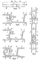
Der Rolladen, das Verfahren zu einer Herstellung und der Hohlprofilstab für Rolladen werden im folgenden anhand der beiliegenden nur schematischen Zeichnungen beispielsweise näher beschrieben. Es zeigen :
- Figur 1 eine Ansicht eines Teiles eines Rolladens,
Figur 2 einen Querschnitt nach der Linie 11-11 in Fig. 1, in grösserem Massstab,Figur 3 einen teilweisen Querschnitt zweier Hohlprofilstäbe in einer zum voneinander Lösen dienenden und auch zum Zusammenfügen geeigneten, gegenseitigen Lage, in noch grösserem Massstab,Figur 4 einen Querschnitt nach der Linie IV-IV in Fig. 1 im Massstab der Fig. 2,Figur 5 eine Teilweise Ansicht in Richtung des Pfeiles V in Fig. 1, im Massstab der Fig. 2 und 4,Figur 6 bis 8 je einen teilweisen Querschnitt zweier nebeneinanderliegender Hohlprofilstäbe in verschiedenen aufeinanderfolgenden Phasen eines Vorgangs, bei dem die Stäbe durch Zusammenstossen miteinander verbunden werden, im Massstab der Fig. 3,Figur 9 eine Variante einer Einzelheit eines Hohlprofilstabes, im Massstab der Fig. 3 und 6 bis 8.
- FIG. 1 shows a view of part of a roller shutter,
- 2 shows a cross section along the line 11-11 in FIG. 1, on a larger scale,
- FIG. 3 shows a partial cross section of two hollow profile bars in a mutual position, which serves to detach from one another and is also suitable for joining, on an even larger scale,
- FIG. 4 shows a cross section along the line IV-IV in FIG. 1 on the scale of FIG. 2,
- 5 shows a partial view in the direction of arrow V in FIG. 1, on the scale of FIGS. 2 and 4,
- 6 to 8 each show a partial cross section of two adjacent hollow profile bars in different successive phases of a process in which the bars are connected to one another by colliding, on the scale of FIG. 3,
- 9 shows a variant of a detail of a hollow profile rod, on the scale of FIGS. 3 and 6 to 8.
Der in Fig. 1, 2, 4 und 5 gezeigte Teil eines Rolladens umfasst fünf Hohlprofilstäbe 1a bis 1e, von denen der Stab 1 b am Stab 1a hängt und auf den übereinander stehenden Stäben lc, 1d und 1e steht. Die Stäbe sind einander gleich und haben, wie Fig. 2 und 4 zeigen, ein flaches, viereckiges Hohlraumprofil mit zwei schmaleren Längsseiten 4 und 5, zwei breiteren Längsseiten 6 und 7 und zwei zur Versteifung dienenden Stegen 2 und 3. Die obere und die untere der schmaleren Längsseiten 4 und 5 verlaufen schiefwinklig zu den breiteren Längsseiten 6 und 7. An dem Rand 8 der Seite 5, an welcher der Winkel zwischen dieser Seite 5 und der angrenzenden Seite 6 stumpf ist, weisen die Seite 5 zwei Langlöcher 9 und die Seite 6 einen die Seite 5 überragenden Vorsprung 10 auf. Diesem Vorsprung 10 ist eine Stufe 11 an der benachbarten Kante 12 des benachbarten Stabes zugeordnet. In diese Stufe 11 greift der Vorsprung 10 hinein, wenn die Stäbe in miteinander fluchtender Lage aneinander anstossen (Stäbe 1b und 1c in Fig. 2 und 4). Dabei sind die Stäbe in Richtung ihrer Dicke durch den Ansatz 10, die Stufe 11 und infolge der Neigung der Seiten 4 und 5 in bezug aufeinander fixiert.The part of a roller shutter shown in FIGS. 1, 2, 4 and 5 comprises five
Unmittelbar an der Stufe 11 hat jeder Stab zwei an der Seite 4 vorstehende Ansätze 13, 14, 15. Jeder Ansatz 13, 14, 15 greift durch eines der Langlöcher 9 an der benachbarten Seite 5 des benachbarten Stabes ein und hat ein in der Stabquerschnittsebene hakenförmig gekrümmtes Ende 14 mit einem nach innen gerichteten Vorsprung 15, der sich in der spitzwinkligen Ecke 16 zwischen der Seite 7 und der Seite 5 auf der letzteren abstützt, wenn die Stäbe aneinander hängen (Stäbe 1a und 1b in Fig. 2 und 4).Immediately at
Die Ansätze 13, 14, 15 sind in Längsrichtung der Stäbe den Langlöchern 9 angepasst, wodurch die Stäbe in Richtung ihrer Länge in bezug aufeinander fixiert sind. In der Stabquerschnittsebene sind die Ansätze 13, 14, 15 wie im folgenden anhand der Fig. 3 beschrieben, derart geformt, dass ihre hakenförmig gekrümmten Enden 14, 15 nur dann in die Langlöcher 9 eingehängt werden können, wenn die Stäbe einen Winkel miteinander einschliessen, der kleiner ist, als der kleinste, beim Aufrollen des Rolladens vorkommende Winkel, und dass die hakenförmig gekrümmten Enden 14, 15 nicht aushaken können, wenn die Stäbe einen grösseren Winkel einschliessen.The
In der in Fig. 3 gezeigten gegenseitigen Lage schliessen die Seiten 7 der nebeneinander liegenden, mit A und B bezeichneten Stäbe einen spitzen Winkel a ein. Die Kante 17, an welcher die Seiten 7 und 4 des Stabes B zusammentreffen, liegt an der Seite 7 des Stabes A, und der Ansatz 13 des Stabes B liegt an der Kante 18, an welcher die Seiten 5 und 7 des Stabes A zusammentreffen. Der das innere Ende des Vorsprungs 15 berührende Kreisbogen 19 mit der Kante 18 als Zentrum verläuft im Langloch 9 dicht neben dessen der Kante 18 zugewandten (näheren) Längsrand 20. Der das hakenförmige Ansatzende 14 aussen berührende Kreisbogen 21 mit der Kante 18 als Zentrum verläuft dicht vor der dem Langloch 9 zugewandten Fläche 22 des Vorsprungs 10. Dies ermöglicht es, das hakenförmige Ansatzende 14, 15 durch das Langloch 9 in den Hohlraum 24 des Stabes A einzuführen, indem der Stab B in Richtung des Pfeiles 23 um die Kante 18 geschwenkt wird. Wird der Stab B danach weiter geschwenkt bis die Stäbe A und B miteinander fluchten (wobei sich sein Ansatz 13 von der Kante 18 des Stabes A löst) oder einfach losgelassen, dann hängt der Stab B am Stab A sowie in Fig. 1, 2 und 4 der Stab 1 am Stab 1a a hängt, wobei der Vorsprung 15 des Ansatzes 13, 14, 15 des unteren Stabes in der spitzwinkligen Ecke 16 zwischen der Seite 7 und der Seite 5 des oberen Stabes auf dessen Seite 5 ruht. Die äussere Weite (der Halbkreisdurchmesser) des Hakenförmigen Ansatzendes 14, 15 ist grösser als die Breite des Langloches 9, so dass der Ansatz 13, 14, 15 nicht aus dem Langloch 9 aushaken kann, es sei denn, die Stäbe würden in die in Fig. 3 dargestellte gegenseitige Lage gebracht, die sie im Gebrauch niemals einnehmen. Jedoch ist die Möglichkeit, die Stäbe in dieser Lage auf entsprechende Weise wieder voneinander zu lösen, bei einer Demontage des Rolladens zeitsparend.In the mutual position shown in FIG. 3, the
Wenn das hakenförmige Ansatzende, wie gezeichnet, halbkreisförmig ist, kann sein äusserer Radius auch wenig kleiner als die Langlochbreite bemessen werden, in welchem Falle das hakenförmige Ansatzende in das Langloch geschoben und herausgezogen werden kann, wenn die Stäbe etwa rechtwinklig zueinander stehen. Im allgemeinen entspricht die Langlochbreite ungefähr der halben Breite der Seite 5.If the hook-shaped attachment end, as drawn, is semicircular, its outer radius can also be dimensioned slightly smaller than the slot width, in which case the hook-shaped attachment end can be pushed into the slot and pulled out when the rods are approximately at right angles to one another. In general, the slot width is approximately half the width of
Die mit den Langlöchern 9 versehene Seite 5 jedes Stabes ist unmittelbar an die Langlöcher 9 anschliessend durchgehend längs geschlitzt, d. h. es erstrecken sich Schlitze 25 von einem Langloch 9 zum anderen und von den äusseren Langlöchern bis an die Stabenden, so dass die Seite 5 aus zwei nicht zusammenhängenden sondern durch die Langlöcher 9 und die Schlitze 25 voneinander getrennten Teilen besteht. Die Weite der Schlitze 25 ist wesentlich kleiner als die Breite der Langlöcher 9. Im dargestellten Beispiel münden die Schlitze 25 in die Langlöcher 9 an deren der Seite 7 zugewandten (näheren) Längsrand 20. Dadurch wird erreicht, dass die Ansätze 13 bei aneinander hängenden und bei aufeinander stehenden Stäben den grösstmöglichen Abstand von den Schlitzen 25 haben und keinesfalls in diese gelangen können. Dies muss vermieden werden, damit benachbarte Stäbe sich nicht in ihrer Längsrichtung gegeneinander verschieben können. Dies wird zusätzlich noch dadurch verhindert, dass die Schlitzweite viel kleiner ist als die Dicke der Ansätze.The
An Stelle der Schlitze 25 können, wie Fig. 9 zeigt, Sollbruchstellen 25a vorgesehen sein, die, wie weiter unten erläutert, vor dem Zusammenfügen der Stäbe gebrochen oder durchgeschnitten oder beim Zusammenstossen der Stäbe (Fig. 5 bis 8) gebrochen werden.Instead of the
Die Wandstärke einer oder beider Seiten 6 und 7, vorzugsweise der Seite 7, ist im Bereich zwischen dem Steg 2 und der Seite 5 so bemessen, dass diese Wandteile federnd nachgeben (spreizen), wenn die hakenförmigen Ansatzenden 14 in die Langlöcher 9 gestossen werden, wie Fig. 6 bis 8 zeigen.The wall thickness of one or both
Um das Einführen der hakenförmigen Ansatzenden 14 in die Langlöcher 9 zu ermöglichen oder zu erleichtern, sind jene in der Stabquerschnittsebene aussen in dem Bereich, in dem sie beim Einführen an den Längsrändern der Langlöcher 9 gleiten, in der von der Seite 4 wegweisenden Richtung verjüngt. Bei der dargestellten, halbkreisförmigen Hakenform ist die Verjüngung durch die in diesem Bereich liegenden Kreisbogenabschnitte gebildet. Die Ansatzenden können aber auch eine andere in diesem Sinne verjüngte Form haben, z. B. etwa V-förmig sein.In order to enable or facilitate the insertion of the hook-shaped attachment ends 14 into the
Durch den in Fig. 6 bis 8 dargestellten Vorgang können mehrere oder alle Stäbe für einen Rolladen auf einmal zusammengefügt werden. Sie werden dazu in Querrichtung ihrer breiteren Längsseiten 6 und 7 verschiebbar so aneinander gereiht, dass die hakenförmigen Ansatzenden 14 des einen von zwei benachbarten Stäben vor den Langlöchern 9 des anderen liegen. Diese Reihe der Stäbe wird an einem Ende an einem Widerlager abgestützt. Die Stäbe werden dann in einem einzigen Arbeitsgang miteinander verbunden, indem auf das andere Ende der Reihe so lange gestossen wird, bis die Ansätze 13, 14 durch die Langlöcher 9 hindurch in den Hohlraum 24 eindringen, und die einander benachbarten schmaleren Längsseiten 4 und 5 aller Stäbe zusammenstossen. Bei der Ausführung mit Sollbruchstellen 25a (Fig. 9) werden diese zur Bildung der Schlitze 25 entweder vor dem Zusammenstossen der Profilstäbe durch einen auf die schmalere Längsseite 5 ausgeübten Schlag oder Druck gebrochen oder mit einem Messer durchgeschnitten oder dadurch gebrochen, dass die hakenförmigen Ansatzenden die Oeffnungen 9 erweitern, wenn sie durch diese hindurchgetrieben werden.6 to 8, several or all of the bars for a roller shutter can be put together at once. For this purpose, they are displaceably lined up in the transverse direction of their wider
Zum Zusammenstossen können die Stäbe zwischen zwei Platten oder zwischen mehreren Leisten angeordnet werden, wobei zusätzlich seitliche Führungsleisten für die Stabenden vorgesehen werden können. Auch können die Stäbe lediglich an ihren Enden in zwei U-Profilleisten verschiebbar gehalten werden. Der Abstand der Platten oder Leisten bzw. der Abstand der beiden U-Schenkel jeder der beiden Profilleisten ist so zu wählen, dass die Profilstabwandteile zwischen dem Steg 2 und der Seite 5 beim Einführen der hakenförmigen Ansatzenden 14 in die Langlöcher 25 wie erwähnt elastisch nachgeben (spreizen) können.To collide, the rods can be arranged between two plates or between several strips, lateral guide strips for the rod ends also being able to be provided. The rods can also be held displaceably at their ends in two U-shaped strips. The distance between the plates or strips or the distance between the two U-legs of each of the two profile strips is to be selected such that the profile rod wall parts between the
Zur gleichmässigen Verteilung des Stosses über die Stablänge wird der Stoss mittels einer sich über die ganze Stablänge erstreckenden Leiste oder einer derartigen Stossbacke ausgeübt. Das Widerlager und die Stossbacke haben zweckmässig Vertiefungen zur Aufnahme der Ansätze 13, 14 bzw. eine Vertiefung zur Aufnahme des Vorsprungs 10, so dass der Stoss auf die schmalere Längsseite 4 bzw. 5 an einem Ende der Reihe ausgeübt bzw. an dieser schmaleren Längsseite am anderen Ende der Reihe vom Widerlager aufgenommen wird.To evenly distribute the joint over the length of the rod, the joint is exerted by means of a bar extending over the entire length of the rod or of such a jaw. The abutment and the butt cheek suitably have recesses for receiving the
Die Stäbe können zwei Ansätze, wie in Fig. 1 gezeigt, oder mehr als zwei Ansätze oder nur einen einzigen Ansatz haben, der sich bis nahe an die Stabenden erstreckt, wobei sich die Schlitze 25 bzw. Sollbruchstellen 25a zwischen den Enden des Langlochs und den Stabenden erstrecken. Die in Stablängsrichtung liegende Abmessung der Ansätze kann, wie in Fig. 1 und 5, kleiner aber auch gleich oder grösser als die Schlitzlänge sein.The rods may have two lugs, as shown in Fig. 1, or more than two lugs, or only a single lug that extends close to the bar ends, with the
Die Stäbe werden von in grösserer Länge extrudiertem Hohlprofilstabmaterial in der gewünschten Länge abgeschnitten. Vor oder nach dem Abschneiden werden die Langlöcher 9 gefräst und der beim Extrudieren auf der ganzen Länge des Stranges gebildete Teil des Profils, der den Querschnitt des Ansatzes 13, 14, 15 hat, ausserhalb der zu bildenden Ansätze entfernt (weggefräst). Zur Bildung der Schlitze bzw. Sollbruchstellen kann das Stabprofil mit einem fortlaufenden Schlitz oder einer fortlaufenden Sollbruchstelle extrudiert werden. In diesem Fall hat die Ausführungsform mit Sollbruchstellen den Vorteil, dass die Langlöcher in die ein Ganzes bildende, d. h. nicht durch einen fortlaufenden Schlitz geteilte Hohlstabwand gefräst werden, was die Fräsarbeit erleichtert. Bei der Ausführungsform mit Schlitzen kann dieser Vorteil dadurch erreicht werden, dass das Hohlprofil ohne den fortlaufenden Schlitz extrudiert und die Schlitze nach dem Fräsen der Langlöcher gefräst werden.The rods are cut to the desired length from hollow profile rod material extruded in greater length. Before or after cutting, the
Die Langlöcher und die Schlitze können auch dadurch gebildet werden, dass das Hohlstabprofil mit einer durchgehenden Längsöffnung hergestellt (extrudiert) ist, die an wenigstens einer Stelle des Stabes durch ein dort angebrachtes (z. B. angeklebtes oder angeschweisstes) Stück verengt ist, um eine schlitzartige Verengung der Längsöffnung zu erzielen, wobei die Längsöffnung beiderseits der Verengung Langlöcher bildet. Dabei ist der Umfang von Langlöchern, die unmittelbar an eine Stabstirnseite angrenzen, an dieser unterbrochen. Die Schlitze können statt durch Anbringen solcher Stücke auch dadurch erhalten werden, dass das Hohlstabprofil mit einer Längsöffnung extrudiert wird, die an wenigstens einem ihrer Längsränder einen nach innen gebogenen Rand hat, der an den betreffenden Stellen zur Verengung der Längsöffnung in die Lochebene gebogen wird. Dazu wird zweckmässig ein an der Extruderdüse angebrachtes Werkzeug (Biegezange) periodisch betätigt, um das extrudierte, noch plastische Material in Zeitabständen, die den Langlochlängen entsprechen, an einer der Schlitzlänge entsprechenden Stelle zu biegen. Selbstverständlich kann dazu auch ein selbständiges, geheiztes Biegewerkzeug (Biegezange) dienen.The elongated holes and the slots can also be formed in that the hollow bar profile is produced (extruded) with a continuous longitudinal opening which is narrowed by at least one point on the bar by a piece attached (e.g. glued or welded on) by one to achieve slot-like narrowing of the longitudinal opening, the longitudinal opening forming elongated holes on both sides of the narrowing. The circumference of elongated holes that directly adjoin a face of the rod is interrupted at this. Instead of attaching such pieces, the slots can also be obtained by extruding the hollow rod profile with a longitudinal opening which has an inwardly curved edge on at least one of its longitudinal edges, which is bent into the hole plane at the relevant points to narrow the longitudinal opening. For this purpose, a tool (bending pliers) attached to the extruder nozzle is expediently actuated periodically in order to bend the extruded, still plastic material at intervals corresponding to the elongated hole lengths at a point corresponding to the slot length. Of course, an independent, heated bending tool (bending pliers) can also be used.
Die Hohlprofilstäbe können im übrigen alle Merkmale der aus der CH-A-539190 bekannten Hohlprofilleisten haben.The hollow profile bars can have all the features of the hollow profile strips known from CH-A-539190.
Claims (12)
Priority Applications (1)
| Application Number | Priority Date | Filing Date | Title |
|---|---|---|---|
| AT80106425T ATE8689T1 (en) | 1979-10-31 | 1980-10-22 | ROLLER SHUTTER, METHOD OF MANUFACTURE THE SAME AND HOLLOW BAR FOR ROLLER SHUTTER. |
Applications Claiming Priority (4)
| Application Number | Priority Date | Filing Date | Title |
|---|---|---|---|
| CH974679 | 1979-10-31 | ||
| CH9746/79 | 1979-10-31 | ||
| CH11298/79 | 1979-12-20 | ||
| CH1129879 | 1979-12-20 |
Publications (2)
| Publication Number | Publication Date |
|---|---|
| EP0028733A1 EP0028733A1 (en) | 1981-05-20 |
| EP0028733B1 true EP0028733B1 (en) | 1984-07-25 |
Family
ID=25705263
Family Applications (1)
| Application Number | Title | Priority Date | Filing Date |
|---|---|---|---|
| EP19800106425 Expired EP0028733B1 (en) | 1979-10-31 | 1980-10-22 | Roller shutter, process for manufacturing same and hollow slat for roller shutters |
Country Status (4)
| Country | Link |
|---|---|
| EP (1) | EP0028733B1 (en) |
| DE (1) | DE3068708D1 (en) |
| ES (1) | ES253986Y (en) |
| GR (1) | GR69905B (en) |
Families Citing this family (3)
| Publication number | Priority date | Publication date | Assignee | Title |
|---|---|---|---|---|
| DE3840601C1 (en) * | 1988-12-02 | 1990-04-26 | Hcr-Heinrich Cremer Gmbh, 4050 Moenchengladbach, De | Covering device which can be shortened and lengthened and is intended for machine beds |
| GB9408072D0 (en) * | 1994-04-22 | 1994-06-15 | Ra Extrusions Ltd | Closure arrangement |
| ES2217900B1 (en) * | 2001-07-25 | 2006-02-01 | Jose Antonio Muñoz Escribano | PERFECTED BLIND SHEET. |
Family Cites Families (6)
| Publication number | Priority date | Publication date | Assignee | Title |
|---|---|---|---|---|
| DE1253897B (en) * | 1961-03-29 | 1967-11-09 | Xilos Societa Per L Ind Genera | Roller shutter strip with longitudinal gap and anchoring profile |
| DE1942707U (en) * | 1966-05-11 | 1966-07-21 | Gerhardi & Cie | ROLLER SHUTTERS. |
| CH539190A (en) * | 1971-08-16 | 1973-07-15 | Profex Ag Kunststoffwerk | Roll-up curtain or roll-up base made of hollow profile strips |
| DE7517475U (en) * | 1975-06-03 | 1977-10-06 | Kufa Gmbh, 7257 Ditzingen | ROLLER SHUTTERS |
| DE2524404C3 (en) * | 1975-06-03 | 1979-05-03 | Kufa Gmbh, 7257 Ditzingen | Device for the production of a roller shutter curtain |
| DE7719916U1 (en) * | 1975-06-03 | 1977-10-06 | Kufa Gmbh, 7257 Ditzingen | DEVICE FOR MANUFACTURING A ROLLER SHUTTER |
-
1980
- 1980-10-20 GR GR63197A patent/GR69905B/el unknown
- 1980-10-22 EP EP19800106425 patent/EP0028733B1/en not_active Expired
- 1980-10-22 DE DE8080106425T patent/DE3068708D1/en not_active Expired
- 1980-10-30 ES ES1980253986U patent/ES253986Y/en not_active Expired
Also Published As
| Publication number | Publication date |
|---|---|
| GR69905B (en) | 1982-07-20 |
| EP0028733A1 (en) | 1981-05-20 |
| ES253986U (en) | 1981-02-16 |
| ES253986Y (en) | 1981-08-16 |
| DE3068708D1 (en) | 1984-08-30 |
Similar Documents
| Publication | Publication Date | Title |
|---|---|---|
| DE2940522C2 (en) | Arrangement of belt connectors made of metal | |
| DE3208749C2 (en) | windshield wipers | |
| AT396156B (en) | METAL PIPE FRAME | |
| DE3144736A1 (en) | STRETCHMETAL WORKPIECE AND METHOD FOR PRODUCING THE SAME | |
| EP3303731B1 (en) | Framework platform element, in particular for scaffolding | |
| DE3405986C2 (en) | ||
| CH691616A5 (en) | Plastic window and method for its production. | |
| EP0028733B1 (en) | Roller shutter, process for manufacturing same and hollow slat for roller shutters | |
| EP0016958B1 (en) | Frame section for a window, a door or the like | |
| EP0032408A2 (en) | Thermally insulating profile member | |
| EP0681083B1 (en) | Plastic straight connector for hollow spacer and transom profiles in multi-pane insulating glazing | |
| DE3120897A1 (en) | Press for producing beams or sheets from glued rods | |
| EP0172575B1 (en) | Connecting arrangement | |
| CH652565A5 (en) | Element which can be coupled to other similar elements for forming a delimitation of a lawn area from an adjacent open-land area | |
| DE3512206A1 (en) | Panels for cladding facades or the like | |
| CH539190A (en) | Roll-up curtain or roll-up base made of hollow profile strips | |
| DE2903107C2 (en) | Spacers for sprinkler plates of atmospheric cooling devices | |
| DE3809748C2 (en) | Toggle connection for the add-on parts of conveyor troughs | |
| DE3535834A1 (en) | Lamella profile for roller blinds | |
| DE2951393A1 (en) | Interlocking hollow roller shutter slats - has narrow slits between cut=outs for hooks on adjacent slats | |
| EP3179026B1 (en) | Corner connector for door or window hollow profiles | |
| DE3638969A1 (en) | Shutter for rolling shutter doors | |
| DE3117817C2 (en) | ||
| DE2308451C3 (en) | Energy chain made of plastic | |
| DE1434087C (en) | Plate-shaped component |
Legal Events
| Date | Code | Title | Description |
|---|---|---|---|
| PUAI | Public reference made under article 153(3) epc to a published international application that has entered the european phase |
Free format text: ORIGINAL CODE: 0009012 |
|
| AK | Designated contracting states |
Designated state(s): AT BE CH DE FR GB IT |
|
| 17P | Request for examination filed |
Effective date: 19811026 |
|
| ITF | It: translation for a ep patent filed |
Owner name: STUDIO APRA' BREVETTI |
|
| GRAA | (expected) grant |
Free format text: ORIGINAL CODE: 0009210 |
|
| AK | Designated contracting states |
Designated state(s): AT BE CH DE FR GB IT LI |
|
| REF | Corresponds to: |
Ref document number: 8689 Country of ref document: AT Date of ref document: 19840815 Kind code of ref document: T |
|
| REF | Corresponds to: |
Ref document number: 3068708 Country of ref document: DE Date of ref document: 19840830 |
|
| PG25 | Lapsed in a contracting state [announced via postgrant information from national office to epo] |
Ref country code: AT Effective date: 19841022 |
|
| ET | Fr: translation filed | ||
| PLBE | No opposition filed within time limit |
Free format text: ORIGINAL CODE: 0009261 |
|
| STAA | Information on the status of an ep patent application or granted ep patent |
Free format text: STATUS: NO OPPOSITION FILED WITHIN TIME LIMIT |
|
| 26N | No opposition filed | ||
| PG25 | Lapsed in a contracting state [announced via postgrant information from national office to epo] |
Ref country code: BE Effective date: 19851031 |
|
| GBPC | Gb: european patent ceased through non-payment of renewal fee | ||
| BERE | Be: lapsed |
Owner name: STEINEBERG KURT Effective date: 19851031 |
|
| PG25 | Lapsed in a contracting state [announced via postgrant information from national office to epo] |
Ref country code: FR Free format text: LAPSE BECAUSE OF NON-PAYMENT OF DUE FEES Effective date: 19870630 |
|
| REG | Reference to a national code |
Ref country code: FR Ref legal event code: ST |
|
| PGFP | Annual fee paid to national office [announced via postgrant information from national office to epo] |
Ref country code: DE Payment date: 19880926 Year of fee payment: 9 |
|
| PG25 | Lapsed in a contracting state [announced via postgrant information from national office to epo] |
Ref country code: GB Free format text: LAPSE BECAUSE OF NON-PAYMENT OF DUE FEES Effective date: 19881118 |
|
| PG25 | Lapsed in a contracting state [announced via postgrant information from national office to epo] |
Ref country code: LI Effective date: 19891031 Ref country code: CH Effective date: 19891031 |
|
| REG | Reference to a national code |
Ref country code: CH Ref legal event code: PL |
|
| PG25 | Lapsed in a contracting state [announced via postgrant information from national office to epo] |
Ref country code: DE Effective date: 19900703 |