EP0025556B1 - An impact absorbing bumper unit for a vehicle - Google Patents
An impact absorbing bumper unit for a vehicle Download PDFInfo
- Publication number
- EP0025556B1 EP0025556B1 EP19800105255 EP80105255A EP0025556B1 EP 0025556 B1 EP0025556 B1 EP 0025556B1 EP 19800105255 EP19800105255 EP 19800105255 EP 80105255 A EP80105255 A EP 80105255A EP 0025556 B1 EP0025556 B1 EP 0025556B1
- Authority
- EP
- European Patent Office
- Prior art keywords
- bumper
- reinforcing member
- impact absorbing
- cover
- vehicle
- Prior art date
- Legal status (The legal status is an assumption and is not a legal conclusion. Google has not performed a legal analysis and makes no representation as to the accuracy of the status listed.)
- Expired
Links
- 230000003014 reinforcing effect Effects 0.000 claims description 49
- 238000006073 displacement reaction Methods 0.000 claims description 2
- 238000010276 construction Methods 0.000 description 7
- 239000000463 material Substances 0.000 description 6
- 239000011248 coating agent Substances 0.000 description 4
- 238000000576 coating method Methods 0.000 description 4
- 239000011358 absorbing material Substances 0.000 description 2
- 238000010521 absorption reaction Methods 0.000 description 2
- 238000009434 installation Methods 0.000 description 2
- 239000013013 elastic material Substances 0.000 description 1
- JEIPFZHSYJVQDO-UHFFFAOYSA-N iron(III) oxide Inorganic materials O=[Fe]O[Fe]=O JEIPFZHSYJVQDO-UHFFFAOYSA-N 0.000 description 1
- 238000000034 method Methods 0.000 description 1
- 239000004033 plastic Substances 0.000 description 1
- 239000002984 plastic foam Substances 0.000 description 1
- 230000002265 prevention Effects 0.000 description 1
Images

Classifications
-
- B—PERFORMING OPERATIONS; TRANSPORTING
- B60—VEHICLES IN GENERAL
- B60R—VEHICLES, VEHICLE FITTINGS, OR VEHICLE PARTS, NOT OTHERWISE PROVIDED FOR
- B60R19/00—Wheel guards; Radiator guards, e.g. grilles; Obstruction removers; Fittings damping bouncing force in collisions
- B60R19/02—Bumpers, i.e. impact receiving or absorbing members for protecting vehicles or fending off blows from other vehicles or objects
- B60R19/18—Bumpers, i.e. impact receiving or absorbing members for protecting vehicles or fending off blows from other vehicles or objects characterised by the cross-section; Means within the bumper to absorb impact
-
- B—PERFORMING OPERATIONS; TRANSPORTING
- B60—VEHICLES IN GENERAL
- B60R—VEHICLES, VEHICLE FITTINGS, OR VEHICLE PARTS, NOT OTHERWISE PROVIDED FOR
- B60R19/00—Wheel guards; Radiator guards, e.g. grilles; Obstruction removers; Fittings damping bouncing force in collisions
- B60R19/02—Bumpers, i.e. impact receiving or absorbing members for protecting vehicles or fending off blows from other vehicles or objects
- B60R19/18—Bumpers, i.e. impact receiving or absorbing members for protecting vehicles or fending off blows from other vehicles or objects characterised by the cross-section; Means within the bumper to absorb impact
- B60R2019/186—Additional energy absorbing means supported on bumber beams, e.g. cellular structures or material
-
- B—PERFORMING OPERATIONS; TRANSPORTING
- B60—VEHICLES IN GENERAL
- B60R—VEHICLES, VEHICLE FITTINGS, OR VEHICLE PARTS, NOT OTHERWISE PROVIDED FOR
- B60R19/00—Wheel guards; Radiator guards, e.g. grilles; Obstruction removers; Fittings damping bouncing force in collisions
- B60R19/02—Bumpers, i.e. impact receiving or absorbing members for protecting vehicles or fending off blows from other vehicles or objects
- B60R19/18—Bumpers, i.e. impact receiving or absorbing members for protecting vehicles or fending off blows from other vehicles or objects characterised by the cross-section; Means within the bumper to absorb impact
- B60R2019/1886—Bumper fascias and fastening means therefor
Definitions
- the invention is related to an impact absorbing bumper unit for a vehicle, said bumper unit having a bumper reinforcing member secured to a vehicle body, an impact absorbing member disposed between said bumper reinforcing member and a bumper cover, which bumper cover is arranged to cover said impact absorbing member and is held by mounting means on said bumper reinforcing member, which mounting means is arranged to allow a portion of said bumper cover a displacement in the longitudinal direction of the vehicle toward said bumper reinforcing member when an external force caused by a collision of the vehicle is applied to said bumper unit.
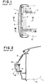
- a front bumper unit generally denoted by reference numeral 1 comprises a bumper reinforcing member 2, an impact absorbing member 3 and a bumper cover 4.
- the bumper reinforcing member 2 is secured by means of bolts to bumper stays 6 which is fixed to side members 7 of a vehicle body.
- Upper and lower flange sections 4a and 4b of the bumper cover 4 are fastened by means of bolts to upper and lower sections 2a and 2b of the bumper reinforcing member 2, respectively.
- the upper and lower flange sections 4a and 4b of the bumper cover 4 are integrally and rigidly fastened to the upper and lower sections 2a and 2b of the bumper reinforcing member 2.
- the bumper cover 4 and the impact absorbing member 3 are deformed largely in the vertical direction when the bumper unit 1 absorbs impact energy in a light collision of the vehicle, so that the bumper cover 4 and the impact absorbing member 3 come into contact with a radiator grille 9 or other vehicle body members, thus to cause damage to these vehicle body members.
- the bumper cover 4 and the impact absorbing member 3 come into contact with a radiator grille 9 or other vehicle body members, thus to cause damage to these vehicle body members.
- the bumper cover must be renewed always after a light collision.
- the bumper reinforcing member 2 must be installed on the vehicle body from the inside of a wheel housing portion 11 of a front fender 10, and therefore the installation of the bumper unit is very troublesome.
- An impact absorbing bumper unit for a vehicle as described at the beginning of this description is known from the DE-A1-2751 077.
- the impact absorbing member disposed between the bumper reinforcing member and a bumper cover has to be disposed such that it fills completely the space between these two parts. Since this space has to be completely filled, quite a large amount of impact absorbing material is necessary.
- Such an impact absorbing material is normally made of some plastic or plastic foam material and is therefore relatively expensive.
- special fastening means are necessary for fastening the end portions of the bumper cover to the vehicle. Since these fastening means are not sufficient for the bumper cover, additional means are provided to hold the bumper cover on the reinforcing member, to achieve the stability required.
- the impact absorbing properties of this known bumper unit are determined by the material and the shape of the bumper cover, and by the characteristics of the elastic material and the shape and material of the bumper reinforcing member. Therefore, it is difficult to control the impact absorption properties.
- the object of the invention consists therefore in improving an impact absorbing bumper unit according to the generic portion of claim 1 such that it has a simple construction and that the impact absorption properties may be better controlled.
- the impact absorbing bumper unit according to the invention has an extremely simple construction.
- the impact absorbing characteristics of the bumper unit according to the invention are determined by the shape and the characteristics of the material of the bumer cover and by the shape and the characteristics of the material of the bumper reinforcing member. A further parameter of the impact absorbing characteristics depends on the material and the shape of the impact absorbing member disposed between the bumper cover and the bumper reinforcing member.
- the bumper unit according to the invention has an additional parameter determining the overall impact absorbing characteristics of the bumper unit.
- This additional parameter is the possibility of a sliding movement between the bumper cover and the bumper reinforcing member.
- the bumper cover moves toward the bumper reinforcing member absorbing thereby a certain amount of impact energy.
- the mounting means for the bumper cover are not only used to fasten the bumper cover but also to provide impact energy absorbing properties.
- the bumper cover disclosed in the aforementioned DE-A1-2751077 is fixedly mounted by special mounting means to the vehicle.
- the holding means in the form of a bolt and a screw are not used to fasten the cover but rather to hold it for a slidable movement in the direction of the vehicle.
- the impact absorbing bumper unit according to the invention is arranged not to be deformed in the vertical direction in a collision of the vehicle so that damages to a radiator grille or other vehicle body members are prevented. Furthermore, the occurrence of cracks in fastening portions between the bumper cover and the bumper reinforcing member of such a bumper unit is prevented.
- a further development of the invention is characterized in that said bumper cover is fastened to said bumper reinforcing member in such a manner that there is provided a clearance between said impact absorbing member and the outer face of said bumper reinforcing member for allowing said bumper cover and said impact absorbing member to slightly move toward said bumper reinforcing member when an external force caused by a collision of the vehicle is applied to said bumper unit.
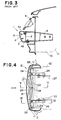
- a front bumper unit according to the present invention is generally denoted by reference numeral 21, and the front bumper unit 21 comprises a bumper reinforcing member 22 which is fixed by means of bolts to bumper stays 26 which are in turn fixed to front side members 27 of a vehicle body, an impact absorbing member 23 disposed in front of the bumper reinforcing member 22, and a bumper cover 24 covering the surface of the impact absorbing member 23.
- the bumper cover 24 generally has upper and lower plate sections 24a and 24b extending longitudinally of the vehicle.
- the bumper reinforcing member 22 generally has upper and lower sections 22a and 22b.
- the upper and lower plate sections 24a and 24b of the bumper cover 24 are fastened by means of bolts 28 to the upper and lower sections 22a and 22b of the bumper reinforcing member 22.
- elongate holes or slots 29 elongated longitudinally of the vehicle and the length L of the elongate holes is made slightly longer than a distance for movement D which is formed between the impact absorbing member 23 of the bumper cover 24 and the front side of the bumper reinforcing member 22.
- This distance for movement D allows the bumper cover 24 to move rearwards through the distance D when the bumper cover 24 and the impact absorbing member 23 absorb and dissipate impact energy in a light collision, and thus serves to prevent a large deformation in the vertical direction of the bumper cover 24 and the impact absorbing member 23 as well as to prevent occurrence of cracks in the surface of the bumper cover 24.
- the bumper unit of the present invention is assembled as follows: Before vehicle body coating operation, the bumper reinforcing member 22 of the bumper unit 21 is fastened by means of bolts to the bumper stays 26 which are fixed to the front side members 27 of the vehicle body. Then after the body coating operation, the impact absorbing member 23 and the bumper cover 24 are fastened to the bumper reinforcing member 22 by means of bolts.
- the bumper cover 24 is fastened to the bumper reinforcing member 22 in such a manner that the fastening bolts therebetween are positioned at the rear end of the elongate hole elongated longitudinally of the vehicle and therefore there is formed between the front surface of the bumper reinforcing member 22 and the impact absorbing member 23 a distance D slightly shorter than the length L of the elongate holes.
- the bumper unit 21 When an external force as shown in Fig. 4 is applied to the front bumper unit 21 arranged in this way, the bumper unit 21 is deformed as shown by phantom lines in Fig. 4. That is, the portion of the front bumper unit near the center of the vehicle width slides along the elongate holes toward the vehicle. However the front bumper unit of the present invention is not deformed in the vertical direction.
- a front bumper is taken as an example
- the present invention is, of course, applicable also to a rear bumper.
- the elongate holes 29 are formed on the side of the bumper cover 24 but these elongate holes may be formed in the upper and lower sections of the bumper reinforcing member 22.
- the bumper cover 24 and the impact absorbing member 23 are formed integrally or separately is not important to the present invention.
- the bumper unit of the present invention is not deformed in the vertical direction and does not cause damages to a radiator or other vehicle body members.
- the bumper unit of the present invention is free from cracks after deformed in a collision and therefore the deformed bumper unit is easily restored to the original state.
- the bumper cover is mounted on the bumper reinforcing member by fastening them by means of bolts at the upper and lower sections of the bumper reinforcing member. Therefore the bumper reinforcing member can be installed before a body coating operation and then, after the body coating operation, the bumper cover and the impact absorbing member can be installed. As a result, a rust prevention process for the bumper reinforcing member becomes unnecessary and the mounting operation is made very easy because the bumper reinforcing member can be installed on the bumper stays before the installation of the front fender.
Landscapes
- Engineering & Computer Science (AREA)
- Mechanical Engineering (AREA)
- Body Structure For Vehicles (AREA)
- Vibration Dampers (AREA)
Applications Claiming Priority (2)
| Application Number | Priority Date | Filing Date | Title |
|---|---|---|---|
| JP125048/79U | 1979-09-12 | ||
| JP12504879U JPS598912Y2 (ja) | 1979-09-12 | 1979-09-12 | 衝撃吸収バンパ構造 |
Publications (2)
| Publication Number | Publication Date |
|---|---|
| EP0025556A1 EP0025556A1 (en) | 1981-03-25 |
| EP0025556B1 true EP0025556B1 (en) | 1984-03-21 |
Family
ID=14900537
Family Applications (1)
| Application Number | Title | Priority Date | Filing Date |
|---|---|---|---|
| EP19800105255 Expired EP0025556B1 (en) | 1979-09-12 | 1980-09-03 | An impact absorbing bumper unit for a vehicle |
Country Status (3)
| Country | Link |
|---|---|
| EP (1) | EP0025556B1 (enExample) |
| JP (1) | JPS598912Y2 (enExample) |
| DE (1) | DE3067153D1 (enExample) |
Cited By (1)
| Publication number | Priority date | Publication date | Assignee | Title |
|---|---|---|---|---|
| DE102009057835A1 (de) * | 2009-12-10 | 2011-06-16 | Audi Ag | Stoßfänger für ein Kraftfahrzeug |
Families Citing this family (10)
| Publication number | Priority date | Publication date | Assignee | Title |
|---|---|---|---|---|
| JPS58165284U (ja) * | 1982-04-30 | 1983-11-02 | 株式会社安永鉄工所 | ダイヤフラムブロワに係わる振動子 |
| JPS61247883A (ja) * | 1985-04-24 | 1986-11-05 | Matsushita Electric Works Ltd | ダイアフラムポンプの駆動部 |
| JPH063190B2 (ja) * | 1985-09-25 | 1994-01-12 | 松下電工株式会社 | 電磁式ポンプ駆動装置 |
| JPS62113873A (ja) * | 1985-11-13 | 1987-05-25 | Sanee Denki Kk | 電磁ポンプの磁気回路 |
| JPS62193553A (ja) * | 1986-02-18 | 1987-08-25 | Yaskawa Electric Mfg Co Ltd | 永久磁石形リニア電磁アクチユエ−タ |
| US4877279A (en) * | 1987-09-03 | 1989-10-31 | General Motors Corp. | Stroking fascia for vehicle energy absorbing bumper systems |
| GB2322602A (en) * | 1997-02-17 | 1998-09-02 | Lin Pac Mouldings | Bumper assemblies for motor vehicles |
| FR2804390B1 (fr) * | 2000-01-27 | 2002-04-26 | Renault | Dispositif d'absorption de choc pour vehicule automobile |
| WO2007129959A1 (en) * | 2006-05-05 | 2007-11-15 | Volvo Lastvagnar Ab | Arrangement for underrun protection for a vehicle. |
| GB2486253A (en) * | 2010-12-09 | 2012-06-13 | Sandeep Kumar Anand | Safety bumper |
Family Cites Families (2)
| Publication number | Priority date | Publication date | Assignee | Title |
|---|---|---|---|---|
| IT1072001B (it) * | 1976-11-15 | 1985-04-10 | Stars Spa | Paraurti ad assorbimento di energia particolarmente per autovetture |
| FR2402551A2 (fr) * | 1977-09-12 | 1979-04-06 | Citroen Sa | Perfectionnements apportes aux pare-chocs de vehicules |
-
1979
- 1979-09-12 JP JP12504879U patent/JPS598912Y2/ja not_active Expired
-
1980
- 1980-09-03 DE DE8080105255T patent/DE3067153D1/de not_active Expired
- 1980-09-03 EP EP19800105255 patent/EP0025556B1/en not_active Expired
Cited By (2)
| Publication number | Priority date | Publication date | Assignee | Title |
|---|---|---|---|---|
| DE102009057835A1 (de) * | 2009-12-10 | 2011-06-16 | Audi Ag | Stoßfänger für ein Kraftfahrzeug |
| DE102009057835B4 (de) * | 2009-12-10 | 2014-07-24 | Audi Ag | Stoßfänger für ein Kraftfahrzeug |
Also Published As
| Publication number | Publication date |
|---|---|
| JPS5642448U (enExample) | 1981-04-18 |
| EP0025556A1 (en) | 1981-03-25 |
| DE3067153D1 (en) | 1984-04-26 |
| JPS598912Y2 (ja) | 1984-03-21 |
Similar Documents
| Publication | Publication Date | Title |
|---|---|---|
| EP0025556A1 (en) | An impact absorbing bumper unit for a vehicle | |
| KR100297292B1 (ko) | 차량용 범퍼 | |
| KR19980043327A (ko) | 자동차용 범퍼의 충격 흡수장치 | |
| JPS5846920Y2 (ja) | 自動車用バンパ−サイドの取付構造 | |
| KR200141615Y1 (ko) | 충격흡수를 위한 차량의 시트 마운팅구조 | |
| KR970000438B1 (ko) | 차량범퍼의 강화구조 | |
| KR100236211B1 (ko) | 자동차의 정면충돌 에너지 흡수부재 | |
| KR200144493Y1 (ko) | 자동차의 범퍼 스테이 충격 완화 구조 | |
| KR200161593Y1 (ko) | 충격 흡수용 겹판 스프링이 내장된 자동차 범퍼 | |
| KR0115989Y1 (ko) | 차량의 충격홉스빔과 범퍼페셔 체결구조 | |
| KR0119204Y1 (ko) | 자동차의 충격흡수빔과 페시아사이의 보강판 장착구조 | |
| KR0123501Y1 (ko) | 차량의 전면 라디에이터 써포트용 프레임 구조 | |
| KR100231534B1 (ko) | 범퍼 리인포스먼트구조 | |
| KR100334278B1 (ko) | 자동차의 전면 범퍼가드 고정장치 | |
| KR200152676Y1 (ko) | 프론트 범퍼페시아 변형방지용 브라켓 | |
| JPH061493Y2 (ja) | 車両における樹脂製バンパの取付構造 | |
| KR200189169Y1 (ko) | 차량용 센터필러 구조 | |
| KR100325262B1 (ko) | 차량용 범퍼 고정구조 | |
| KR100231579B1 (ko) | 자동차의 도어 사이드 프로텍터 | |
| KR0121954B1 (ko) | 자동차의 후방 충돌에 의한 충격 흡수 구조 | |
| KR0160029B1 (ko) | 자동차의 범퍼지지 차체 완충구조 | |
| KR0131508B1 (ko) | 도어의 보강구조 | |
| KR200144097Y1 (ko) | 자동차 전면프로텍터의 취부구조 | |
| KR0115977Y1 (ko) | 차량의 범퍼스테이구조 | |
| KR200154664Y1 (ko) | 범퍼 |
Legal Events
| Date | Code | Title | Description |
|---|---|---|---|
| PUAI | Public reference made under article 153(3) epc to a published international application that has entered the european phase |
Free format text: ORIGINAL CODE: 0009012 |
|
| AK | Designated contracting states |
Designated state(s): DE FR GB |
|
| 17P | Request for examination filed |
Effective date: 19810616 |
|
| GRAA | (expected) grant |
Free format text: ORIGINAL CODE: 0009210 |
|
| AK | Designated contracting states |
Designated state(s): DE FR GB |
|
| REF | Corresponds to: |
Ref document number: 3067153 Country of ref document: DE Date of ref document: 19840426 |
|
| ET | Fr: translation filed | ||
| PGFP | Annual fee paid to national office [announced via postgrant information from national office to epo] |
Ref country code: FR Payment date: 19841022 Year of fee payment: 5 |
|
| PGFP | Annual fee paid to national office [announced via postgrant information from national office to epo] |
Ref country code: DE Payment date: 19841030 Year of fee payment: 5 |
|
| PLBE | No opposition filed within time limit |
Free format text: ORIGINAL CODE: 0009261 |
|
| STAA | Information on the status of an ep patent application or granted ep patent |
Free format text: STATUS: NO OPPOSITION FILED WITHIN TIME LIMIT |
|
| 26N | No opposition filed | ||
| PG25 | Lapsed in a contracting state [announced via postgrant information from national office to epo] |
Ref country code: FR Free format text: LAPSE BECAUSE OF NON-PAYMENT OF DUE FEES Effective date: 19880531 |
|
| PG25 | Lapsed in a contracting state [announced via postgrant information from national office to epo] |
Ref country code: DE Effective date: 19880601 |
|
| GBPC | Gb: european patent ceased through non-payment of renewal fee | ||
| REG | Reference to a national code |
Ref country code: FR Ref legal event code: ST |
|
| PG25 | Lapsed in a contracting state [announced via postgrant information from national office to epo] |
Ref country code: GB Free format text: LAPSE BECAUSE OF NON-PAYMENT OF DUE FEES Effective date: 19881118 |