EP0025488B1 - Notbremszugkasten - Google Patents
Notbremszugkasten Download PDFInfo
- Publication number
- EP0025488B1 EP0025488B1 EP80104126A EP80104126A EP0025488B1 EP 0025488 B1 EP0025488 B1 EP 0025488B1 EP 80104126 A EP80104126 A EP 80104126A EP 80104126 A EP80104126 A EP 80104126A EP 0025488 B1 EP0025488 B1 EP 0025488B1
- Authority
- EP
- European Patent Office
- Prior art keywords
- slider
- valve
- handle
- emergency brake
- opening
- Prior art date
- Legal status (The legal status is an assumption and is not a legal conclusion. Google has not performed a legal analysis and makes no representation as to the accuracy of the status listed.)
- Expired
Links
Images
Classifications
-
- B—PERFORMING OPERATIONS; TRANSPORTING
- B60—VEHICLES IN GENERAL
- B60T—VEHICLE BRAKE CONTROL SYSTEMS OR PARTS THEREOF; BRAKE CONTROL SYSTEMS OR PARTS THEREOF, IN GENERAL; ARRANGEMENT OF BRAKING ELEMENTS ON VEHICLES IN GENERAL; PORTABLE DEVICES FOR PREVENTING UNWANTED MOVEMENT OF VEHICLES; VEHICLE MODIFICATIONS TO FACILITATE COOLING OF BRAKES
- B60T17/00—Component parts, details, or accessories of power brake systems not covered by groups B60T8/00, B60T13/00 or B60T15/00, or presenting other characteristic features
- B60T17/18—Safety devices; Monitoring
- B60T17/20—Safety devices operable by passengers other than the driver, e.g. for railway vehicles
Definitions
- the invention relates to an emergency brake cable box for pneumatic brakes of rail vehicles with a valve and a locking mechanism on a displaceable handle, with a handle attached to it, and on a slide which can be displaced by the pretensioning force of a spring, for forcibly opening the valve by manually actuating the handle.
- Such emergency brake cable boxes serve as a triggering element for the emergency brake. They are installed in the required number in the rail vehicles and are connected to an emergency brake valve via a control line. By pulling an emergency brake handle of the emergency brake cable box, the control line is vented via the valve in the emergency brake cable box and the main line is in turn quickly emptied via the emergency brake valve, so that rapid braking occurs. After applying the emergency brake, the handle remains locked in the pulled position and can only be reset with a suitable square key.
- the object of the present invention is to design an emergency brake cable box in such a way that improper initiation of emergency braking is prevented without the corresponding cable box being identified.
- a rail vehicle for example, three emergency brake train boxes 1 and an emergency brake valve 8 are connected to a control line 7 and the emergency brake valve 8 to a main air line 9.
- the control line 7 is vented by pulling a handle 2 on one of the emergency brake cable boxes 1.
- the emergency brake valve 8 which serves as a relay valve, vents the main line 9 and thus initiates emergency braking.
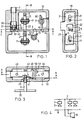
- the emergency brake cable box contains a housing 10, each with a handle 2 and slide 4 arranged displaceably therein, a valve 3 connected to the external control line 7 and a slide device with spring 5 and lever acting on the slide 4 50 and reset device with reset spring 6 and reset pin 60.
- the handle 2 has two slots 21, a recess or link 22, a recess 23 in which one end of the spring 5 is mounted and, according to FIG. 3, one at the outer end attached handle 20 on.
- the valve 3 with the opening 33 is pressed onto the slide 4 by a spring 30, two sealing rings 31 and 32 ensuring the sealing of the control line 7 in the closed state of the valve 3.
- the slide 4 is guided displaceably in the housing 10 according to FIGS. 1 and 3 and passes through the handle 2 in the link 22.
- a lug 42 in cooperation with the link 22 of the handle 2, prevents the slide 4 from moving to the left in the position shown in FIG 1 and 3.
- the slide 4 each has a shoulder 40 and 41 and a bore 43 and 44.
- the spring 5 is designed as a prestressed ring spring. It is mounted on a shaft and, as mentioned above, engages in the recess 23 on the handle 2 and on a cam 51 of the lever 50 such that a displacement force to the left results from the lever 50 on the extension 40 on the slide 4.
- the return spring 6 is also designed as a pretensioned ring spring and is mounted on the shaft of a square key reset device, not shown, in which the reset pin 60, which engages in the bore 44 of the slide 4, is fastened.
- the mode of operation of the emergency brake cable box is as follows: The position shown in FIGS. 1 to 3 shows the state before the emergency braking was triggered.
- the nose 42 of the slide 4 is in contact with the handle 2, thereby preventing a displacement of the slide 4, which is under the force of the spring 5, to the left.
- the bore 43 on the slide 4 is therefore not in register with the valve opening 33.
- the control line 7 is thus closed via the valve 3.
- the slide 4 is moved to the left under the force of the prestressed spring 5 in the link 22 until the shoulder 41 is in contact with the handle 2 .
- the bore 43 is brought into alignment with the valve opening 33 and the control line 7 and, in the sequence, via the emergency brake valve 8, the main line 9 are vented, so that rapid braking starts.
- the handle 2 remains in the lower position as a result of the locking of the nose 42 in the link 22, or the emergency braking can therefore only be triggered after the cooperating nose 42 and link 22 have been locked.
- the actuated Emergency brake cable box can be clearly identified.
- the reset takes place by moving the slide 4 to the right with a special square key via the reset device or via the reset pin 60 engaging in the bore 44.
- claim 1 does not remain limited to this one exemplary embodiment, but also encompasses other designs with interacting backdrops and lugs on the handle and / or slide or vice versa, for example a backdrop in or on slide 4 and a nose on handle 2.
Landscapes
- Engineering & Computer Science (AREA)
- Transportation (AREA)
- Mechanical Engineering (AREA)
- Valves And Accessory Devices For Braking Systems (AREA)
- Regulating Braking Force (AREA)
- Braking Systems And Boosters (AREA)
- Braking Elements And Transmission Devices (AREA)
- Control Of Presses (AREA)
- Braking Arrangements (AREA)
Priority Applications (1)
| Application Number | Priority Date | Filing Date | Title |
|---|---|---|---|
| AT80104126T ATE2779T1 (de) | 1979-09-13 | 1980-07-16 | Notbremszugkasten. |
Applications Claiming Priority (2)
| Application Number | Priority Date | Filing Date | Title |
|---|---|---|---|
| CH8282/79 | 1979-09-13 | ||
| CH828279 | 1979-09-13 |
Publications (2)
| Publication Number | Publication Date |
|---|---|
| EP0025488A1 EP0025488A1 (de) | 1981-03-25 |
| EP0025488B1 true EP0025488B1 (de) | 1983-03-16 |
Family
ID=4337927
Family Applications (1)
| Application Number | Title | Priority Date | Filing Date |
|---|---|---|---|
| EP80104126A Expired EP0025488B1 (de) | 1979-09-13 | 1980-07-16 | Notbremszugkasten |
Country Status (6)
| Country | Link |
|---|---|
| EP (1) | EP0025488B1 (enExample) |
| AT (1) | ATE2779T1 (enExample) |
| DE (1) | DE3062345D1 (enExample) |
| FI (1) | FI69793C (enExample) |
| NO (1) | NO802711L (enExample) |
| PL (1) | PL122806B1 (enExample) |
Families Citing this family (1)
| Publication number | Priority date | Publication date | Assignee | Title |
|---|---|---|---|---|
| DE4310739A1 (de) * | 1993-04-01 | 1994-10-06 | Knorr Bremse Ag | Vorrichtung zum Be- bzw. Entlüften einer Steuerleitung |
Family Cites Families (5)
| Publication number | Priority date | Publication date | Assignee | Title |
|---|---|---|---|---|
| FR619908A (fr) * | 1926-07-12 | 1927-04-12 | Dispositif de blocage pour signaux d'alarme des vagons de chemins de fer, empêchantla remise en place par le voyageur de la poignée de manoeuvre, après sa mise en action | |
| FR880274A (fr) * | 1942-03-17 | 1943-03-22 | Westinghouse Bremsen Gmbh | Boîte pour dispositif de signal d'alarme |
| CH248675A (de) * | 1946-02-22 | 1947-05-15 | Schweiz Wagons Aufzuegefab | Notbremsen-Auslöseinrichtung für Fahrzeuge mit Druckluftbremse. |
| DE1274158B (de) * | 1966-09-30 | 1968-08-01 | Knorr Bremse Gmbh | Notbremsventil fuer Schienenfahrzeuge |
| GB1312223A (en) * | 1971-03-11 | 1973-04-04 | Westinghouse Brake & Signal | Braking systems |
-
1980
- 1980-07-16 EP EP80104126A patent/EP0025488B1/de not_active Expired
- 1980-07-16 DE DE8080104126T patent/DE3062345D1/de not_active Expired
- 1980-07-16 AT AT80104126T patent/ATE2779T1/de active
- 1980-08-26 PL PL1980226421A patent/PL122806B1/pl unknown
- 1980-09-10 FI FI802830A patent/FI69793C/fi not_active IP Right Cessation
- 1980-09-12 NO NO802711A patent/NO802711L/no unknown
Also Published As
| Publication number | Publication date |
|---|---|
| PL122806B1 (en) | 1982-08-31 |
| PL226421A1 (enExample) | 1981-05-22 |
| EP0025488A1 (de) | 1981-03-25 |
| DE3062345D1 (en) | 1983-04-21 |
| FI69793C (fi) | 1986-05-26 |
| ATE2779T1 (de) | 1983-04-15 |
| FI802830A7 (fi) | 1981-03-14 |
| NO802711L (no) | 1981-03-16 |
| FI69793B (fi) | 1985-12-31 |
Similar Documents
| Publication | Publication Date | Title |
|---|---|---|
| DE102006017890A1 (de) | Schaltventil für Anlagen zum Heben und Senken eines Fahrzeugaufbaus | |
| DE202016103804U1 (de) | Kraftfahrzeugschlossanordnung | |
| EP0025488B1 (de) | Notbremszugkasten | |
| DE102011108438A1 (de) | Kraftfahrzeugschloss | |
| EP0300256B1 (de) | Einrichtung zum Fernbetätigen einer automatischen Anhängekupplung | |
| DE3005703C2 (enExample) | ||
| DE2251663A1 (de) | Handsteuerventil fuer bremsanordnungen | |
| DE3607063C2 (enExample) | ||
| DE4222569C2 (de) | Mittelpufferkupplung der Bauart Scharfenberg für Schienenfahrzeuge mit indirekt wirkender Druckluftbremse | |
| EP0491172A1 (de) | Notbremseinrichtung für Druckluftbremsen von Schienenfahrzeugen | |
| DE19705418C2 (de) | Pneumatikschaltung mit Kindersicherung für ein Türschloß eines Kraftfahrzeugs | |
| DE2208453C3 (de) | Antriebseinrichtung zur Betätigung eines Absperrventils | |
| DE962894C (de) | Druckluftbremseinrichtung fuer Schienentriebfahrzeuge mit zwei Fuehrerstaenden | |
| DE4143296C2 (enExample) | ||
| DE688595C (de) | Schloss fuer Verschlussplatten, insbesondere an Luftfahrzeugen | |
| DE69806080T2 (de) | Türschloss für Kraftfahrzeuge | |
| DE572364C (de) | Durch Druckluft oder von Hand betaetigte Rohrleitungskupplung | |
| EP0058990B1 (de) | Verschluss für Aufbauten von Nutzfahrzeugen | |
| CH656847A5 (de) | Mechanische mittelpufferkupplung. | |
| AT229358B (de) | Auslöseeinrichtung für indirekte Druckluftbremsen von Schienenfahrzeugen | |
| DE1925169C3 (de) | Kupplung zum Anschließen eines Einfüllkopfes mit Zuleitung an den Stutzen eines Behälters eines Fahrzeuges, insbesondere eines Tankwagens | |
| DE2309320A1 (de) | Starres schiebedach fuer fahrzeuge mit in schieberichtung beweglichen bremsstangen | |
| EP0082294B1 (de) | Türriegelanschlag, insbesondere für Schwenkschiebetüren von Fahrzeugen | |
| DE730513C (de) | Vorrichtung zum Steuern der Verschluesse an Wetterschleusen | |
| DE939729C (de) | Anhaengerkupplung fuer Fahrzeuge |
Legal Events
| Date | Code | Title | Description |
|---|---|---|---|
| PUAI | Public reference made under article 153(3) epc to a published international application that has entered the european phase |
Free format text: ORIGINAL CODE: 0009012 |
|
| AK | Designated contracting states |
Designated state(s): AT BE CH DE FR GB IT NL SE |
|
| 17P | Request for examination filed |
Effective date: 19810511 |
|
| ITF | It: translation for a ep patent filed | ||
| GRAA | (expected) grant |
Free format text: ORIGINAL CODE: 0009210 |
|
| AK | Designated contracting states |
Designated state(s): AT BE CH DE FR GB IT LI NL SE |
|
| REF | Corresponds to: |
Ref document number: 2779 Country of ref document: AT Date of ref document: 19830415 Kind code of ref document: T |
|
| ET | Fr: translation filed | ||
| REF | Corresponds to: |
Ref document number: 3062345 Country of ref document: DE Date of ref document: 19830421 |
|
| PGFP | Annual fee paid to national office [announced via postgrant information from national office to epo] |
Ref country code: SE Payment date: 19840630 Year of fee payment: 5 |
|
| PG25 | Lapsed in a contracting state [announced via postgrant information from national office to epo] |
Ref country code: SE Effective date: 19860717 |
|
| PGFP | Annual fee paid to national office [announced via postgrant information from national office to epo] |
Ref country code: DE Payment date: 19890630 Year of fee payment: 10 |
|
| PGFP | Annual fee paid to national office [announced via postgrant information from national office to epo] |
Ref country code: NL Payment date: 19890731 Year of fee payment: 10 |
|
| PG25 | Lapsed in a contracting state [announced via postgrant information from national office to epo] |
Ref country code: NL Effective date: 19910201 |
|
| NLV4 | Nl: lapsed or anulled due to non-payment of the annual fee | ||
| PG25 | Lapsed in a contracting state [announced via postgrant information from national office to epo] |
Ref country code: DE Effective date: 19910403 |
|
| PGFP | Annual fee paid to national office [announced via postgrant information from national office to epo] |
Ref country code: FR Payment date: 19910610 Year of fee payment: 12 Ref country code: AT Payment date: 19910610 Year of fee payment: 12 |
|
| PGFP | Annual fee paid to national office [announced via postgrant information from national office to epo] |
Ref country code: GB Payment date: 19910612 Year of fee payment: 12 |
|
| PGFP | Annual fee paid to national office [announced via postgrant information from national office to epo] |
Ref country code: CH Payment date: 19910619 Year of fee payment: 12 |
|
| PGFP | Annual fee paid to national office [announced via postgrant information from national office to epo] |
Ref country code: BE Payment date: 19910624 Year of fee payment: 12 |
|
| ITTA | It: last paid annual fee | ||
| PG25 | Lapsed in a contracting state [announced via postgrant information from national office to epo] |
Ref country code: GB Effective date: 19920716 Ref country code: AT Effective date: 19920716 |
|
| PG25 | Lapsed in a contracting state [announced via postgrant information from national office to epo] |
Ref country code: LI Effective date: 19920731 Ref country code: CH Effective date: 19920731 Ref country code: BE Effective date: 19920731 |
|
| BERE | Be: lapsed |
Owner name: WERKZEUGMASCHINENFABRIK OERLIKON-BUHRLE A.G. Effective date: 19920731 |
|
| GBPC | Gb: european patent ceased through non-payment of renewal fee |
Effective date: 19920716 |
|
| PG25 | Lapsed in a contracting state [announced via postgrant information from national office to epo] |
Ref country code: FR Effective date: 19930331 |
|
| REG | Reference to a national code |
Ref country code: CH Ref legal event code: PL |
|
| REG | Reference to a national code |
Ref country code: FR Ref legal event code: ST |
|
| EUG | Se: european patent has lapsed |
Ref document number: 80104126.0 Effective date: 19870518 |
|
| PLBE | No opposition filed within time limit |
Free format text: ORIGINAL CODE: 0009261 |
|
| STAA | Information on the status of an ep patent application or granted ep patent |
Free format text: STATUS: NO OPPOSITION FILED WITHIN TIME LIMIT |