EP0023565B1 - Anordnung zur Spurlageregelung bei der Aufzeichnung/Wiedergabe von Informationen auf einem scheibenförmigen Magnetaufzeichnungsträger, insbesondere einer flexiblen Magnetfolie, und scheibenförmiger Magnetaufzeichnungsträger dafür - Google Patents
Anordnung zur Spurlageregelung bei der Aufzeichnung/Wiedergabe von Informationen auf einem scheibenförmigen Magnetaufzeichnungsträger, insbesondere einer flexiblen Magnetfolie, und scheibenförmiger Magnetaufzeichnungsträger dafür Download PDFInfo
- Publication number
- EP0023565B1 EP0023565B1 EP80103508A EP80103508A EP0023565B1 EP 0023565 B1 EP0023565 B1 EP 0023565B1 EP 80103508 A EP80103508 A EP 80103508A EP 80103508 A EP80103508 A EP 80103508A EP 0023565 B1 EP0023565 B1 EP 0023565B1
- Authority
- EP
- European Patent Office
- Prior art keywords
- track
- arrangement
- servo
- magnetic
- signal pattern
- Prior art date
- Legal status (The legal status is an assumption and is not a legal conclusion. Google has not performed a legal analysis and makes no representation as to the accuracy of the status listed.)
- Expired
Links
- 230000001419 dependent effect Effects 0.000 title claims description 4
- 238000001208 nuclear magnetic resonance pulse sequence Methods 0.000 claims description 8
- 238000011156 evaluation Methods 0.000 claims description 6
- 230000003247 decreasing effect Effects 0.000 claims description 4
- 230000004907 flux Effects 0.000 claims description 4
- 230000001174 ascending effect Effects 0.000 claims 1
- 230000001788 irregular Effects 0.000 claims 1
- 239000003550 marker Substances 0.000 claims 1
- 238000012217 deletion Methods 0.000 description 7
- 230000037430 deletion Effects 0.000 description 7
- 239000011888 foil Substances 0.000 description 6
- 238000000034 method Methods 0.000 description 5
- 230000008859 change Effects 0.000 description 4
- 238000010586 diagram Methods 0.000 description 3
- 238000004519 manufacturing process Methods 0.000 description 3
- 230000035945 sensitivity Effects 0.000 description 3
- 108010076504 Protein Sorting Signals Proteins 0.000 description 2
- 238000006243 chemical reaction Methods 0.000 description 2
- 238000013500 data storage Methods 0.000 description 2
- 238000013461 design Methods 0.000 description 2
- 238000001514 detection method Methods 0.000 description 2
- 230000005415 magnetization Effects 0.000 description 2
- 230000008569 process Effects 0.000 description 2
- 230000007704 transition Effects 0.000 description 2
- 240000006829 Ficus sundaica Species 0.000 description 1
- 230000008901 benefit Effects 0.000 description 1
- 230000008033 biological extinction Effects 0.000 description 1
- 238000010276 construction Methods 0.000 description 1
- 238000012937 correction Methods 0.000 description 1
- 230000007547 defect Effects 0.000 description 1
- 230000004069 differentiation Effects 0.000 description 1
- 238000006073 displacement reaction Methods 0.000 description 1
- 230000006870 function Effects 0.000 description 1
- 239000000463 material Substances 0.000 description 1
- 230000009467 reduction Effects 0.000 description 1
- 238000007493 shaping process Methods 0.000 description 1
- 210000002023 somite Anatomy 0.000 description 1
- 230000001629 suppression Effects 0.000 description 1
- 230000001960 triggered effect Effects 0.000 description 1
- 238000004804 winding Methods 0.000 description 1
Images

Classifications
-
- G—PHYSICS
- G11—INFORMATION STORAGE
- G11B—INFORMATION STORAGE BASED ON RELATIVE MOVEMENT BETWEEN RECORD CARRIER AND TRANSDUCER
- G11B5/00—Recording by magnetisation or demagnetisation of a record carrier; Reproducing by magnetic means; Record carriers therefor
- G11B5/48—Disposition or mounting of heads or head supports relative to record carriers ; arrangements of heads, e.g. for scanning the record carrier to increase the relative speed
- G11B5/58—Disposition or mounting of heads or head supports relative to record carriers ; arrangements of heads, e.g. for scanning the record carrier to increase the relative speed with provision for moving the head for the purpose of maintaining alignment of the head relative to the record carrier during transducing operation, e.g. to compensate for surface irregularities of the latter or for track following
- G11B5/596—Disposition or mounting of heads or head supports relative to record carriers ; arrangements of heads, e.g. for scanning the record carrier to increase the relative speed with provision for moving the head for the purpose of maintaining alignment of the head relative to the record carrier during transducing operation, e.g. to compensate for surface irregularities of the latter or for track following for track following on disks
- G11B5/59633—Servo formatting
- G11B5/59655—Sector, sample or burst servo format
-
- G—PHYSICS
- G11—INFORMATION STORAGE
- G11B—INFORMATION STORAGE BASED ON RELATIVE MOVEMENT BETWEEN RECORD CARRIER AND TRANSDUCER
- G11B5/00—Recording by magnetisation or demagnetisation of a record carrier; Reproducing by magnetic means; Record carriers therefor
- G11B5/02—Recording, reproducing, or erasing methods; Read, write or erase circuits therefor
- G11B5/024—Erasing
Definitions
- the invention relates to an arrangement for tracking direction when recording / reproducing information on a disk-shaped magnetic recording medium, in particular a flexible magnetic film, by means of a magnetic head which can be adjusted in position across a magnetic adjustment device to the magnetic tracks of the recording medium, with at least one in the course of at least one magnetic track Servo signal pattern for setting the actual head position is recorded, which consists of two parts of the same size, which are arranged one behind the other in the recording direction and with respect to the center of the track in such a way that when the target head is in position, the same number of scanning signals can be evaluated for both parts by an evaluation circuit, but in the case of a track deviation opposing changes in the numbers of the scanning signals evaluable for both parts result, and wherein after scanning the servo signal pattern corresponding to the difference in the numbers of evaluable A for both parts btastsignalen a control signal for the head adjusting device is generated, by which the magnetic head can be reset to the desired head position, and a disk-shaped magnetic recording medium
- the servo signal patterns have two halves with positive / negative oriented servo markings. These servo signal patterns extend in a chain-like manner at an angle across all data tracks.
- a disk-shaped magnetic recording medium for the system according to the invention is specified in claim 8.
- the amplitude envelope of the scanning signals of the servo signal pattern parts can have a triangular shape. This enables very-e gives l hfach be detected waveform.
- the servo signal pattern can consist of a pulse pattern in the track with an at least partially oblique distance range to the track. This results in very simple manufacturing options for this.
- the spacing strip can also be formed from a pulse pattern between neighboring areas that are erased obliquely to the track.
- Such a spacing area or strip can also be produced by overwriting a pulse pattern or by removing the magnetic layer in strips.
- the servo signal pattern parts according to the invention can be generated once by means of amplitude changes generated by means of increasing or decreasing write current.
- servo signal pattern parts can also be formed very favorably by deleting a pulse pattern in the track at an angle to the central track axis.
- the Servo signal pattern parts are separated from each other by an erased security strip.
- a disk-shaped magnetic recording medium, in particular a flexible magnetic film, for the arrangement according to the invention for tracking control can have several, in particular 26, servo signal patterns distributed over the circumference of a magnetic track.
- the oblique, e.g. strip-shaped areas of the servo signal pattern are located on different transverse axes to the tracks of the recording medium.
- a data recording / playback system in which the tracking control according to the invention and the magnetic recording medium designed according to the invention can be used is described schematically below using the example of a magnetic foil memory (floppy disk drive).
- a circular magnetic foil also called FlexyDisk ® (trademark of BASF Aktiengesellschaft) carries data tracks, the formatting of which is standardized.
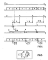
- a data track 27 has 26 sectors, each with a sector identification information (ID) consisting of 13 bytes, an IDG gap, consisting of 11 bytes and the data block (DB) with 137 bytes and the track gap (DG) These format blocks are shown in FIG.
- a servo signal pattern for the tracking control is provided in the track gap DG, whereby the data format is in no way disturbed.
- the initialization of a data track 27 can proceed, for example, as follows. Triggered by a track start signal ST (FIG. 4a), which can be generated by an index mark on the recording disk or by a defect on the magnetic film, continues as a sector identifier run 80xA bytes, 30xS bytes (servo bytes) and 78xB bytes with the read / write gap, for example an A / W header recorded in FIG. A, B and S bytes are easily distinguishable signals, each with a predetermined signal pattern. A bytes are written after the last B bytes until the next track start signal is recognized.
- the written data patterns are recognized and checked in reading mode with the reading channel according to FIG. 1.
- a delay time generator is started for a time period T1.
- an erase current for the erase duration T3 is then supplied to the erase head according to FIG. 5.
- T2 which, in conjunction with T1, controls the erasing current in such a way that it becomes effective only in the area of the S bytes.
- the S-byte areas (servo signal pattern parts) are partially erased by the oblique erasing gap arrangement according to FIG.
- the spatial distance between the sector reference line (SR), which runs approximately through the center of the track gap DG, and the start of the erased oblique strip SS, which represents an important signal characteristic of the servo information according to the invention, is designated by 11.
- the time period T1 can also be varied slightly from track to track, so that the length 11 can be maintained for all tracks - even with circular tracks of different lengths.
- the readability limit can be set to approximately 1/10 to 1/3 of the normal amplitude of the data signals.
- FIG. 4e shows the information content of a track which is obtained after the oblique deletion.
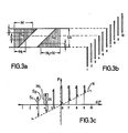
- FIG. 3a shows part of a track 27 according to FIG. 2a described with a servo signal pattern.
- 3b shows ten different positions of a read head gap 28 on the right.
- the minimum read track width of a signal that can still be recognized as a decodable data signal is b.
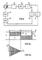
- Such a circuit is shown schematically in FIG. 6.
- the read head 21 is followed by the pulse shaping stage 26, a decoder (DEC) 29 for the S bytes, and a counting circuit, symbolized by a flip-flop arrangement 30, which should have a negative and positive output.
- a servo direct current motor (MOT) 33 is usually controlled via D / A converters (not shown) and the following separate amplifiers 31 and 32, which in turn e.g. controls a position setting device (POS) 34 for the read head 1 within 3 msec.
- POS position setting device
- the position of the read head 21 is adjusted by means of suitable devices, e.g. directly above the head positioner of the drive used.
- the decoder DEC 29 recognizes the information types A, B or S bytes and detects the information transitions. If an A or B signal pattern follows a first S signal pattern, there is no reaction because e.g. there may be misinformation. If a second S-signal pattern part follows a first S-signal pattern part, then the S-signals are switched until a predetermined pause or or when the signal readability limit is reached again, e.g. by means of the counter C, added and after the pause or when the readability of the signal is reached again, the counter is reset step by step by the following S signals, the following S signals (Z2) are thus subtracted.
- the production steps for servo initialization of a magnetic recording medium and the control of the head position of the read head up to the compensation of a possible head position error were described above.
- the servo signal pattern contains as a core an at least partially sloping area SS or SD with a different magnetization to the neighboring areas, which results in different electrical pulse patterns when scanned.
- the strip SS or the triangle SD can be a magnetically erased area within a predetermined fixed pulse pattern, but also a pulse area within an erased area.
- the strip SS can also be an area overwritten by means of a signal in the form of a strip, as well as an area on the magnetic recording medium whose magnetic layer has been removed in the form of a strip (SS) or in another geometric form (SD see FIG. 2b).
- the strip (SS) or the slant line (SD) can e.g. run at an angle of approx. 20 to 70 ° to the transverse axis of the track.
- the edges of the strip SS can run in a straight line, as shown in FIGS. 2a and 3a, but they can also be staircase-shaped (FIG. 2b) by production via gradual deletion with the read-write gap with different track positions (similar to FIG. 3b) of the head gap.
- this read / write head displacement relative to the track can be achieved by means of a head step device, the individual steps of which are fractions of the track width.
- FIG. 7a A servo signal pattern is shown in FIG. 7a.
- the magnetization areas R and P are asymmetrical to the center of the track, but are only consecutive, only separated by a narrow, deleted security strip n1.
- Such a magnetic recording produces a read signal according to FIG. 7b, the amplitudes of each signal range R and P continuously decreasing from their maximum to zero.
- Such a drop in amplitude can be generated during the initialization of a recording medium by a corresponding change in the size of the write current, by oblique extinction similar to the example above, or different flow change intervals by switching the write current on and off at different times.
- the areas Q and U are expediently magnetically dissolved.
- the further measures, recording the data signals, reading and evaluating the scanning signals and readjusting the head position can be carried out as already described above.
- the present track position control it is possible to detect the current actual head position deviating from the target head position and to set the target head position as often as desired within a magnetic track.
- magnetic foils, floppy disks or FlexyDisks it is possible to readjust the head position per circular track 26 times to compensate for an eccentricity of 50 am during one revolution of the foil.
- the necessary initialization of the film or the magnetic disk can be carried out either directly by the manufacturer or only by the user.
- an increase in track density e.g. at least 3 times possible with FlexyDisks.
Landscapes
- Moving Of The Head To Find And Align With The Track (AREA)
- Signal Processing For Digital Recording And Reproducing (AREA)
- Digital Magnetic Recording (AREA)
Applications Claiming Priority (2)
| Application Number | Priority Date | Filing Date | Title |
|---|---|---|---|
| DE19792928311 DE2928311A1 (de) | 1979-07-13 | 1979-07-13 | Spurlageregelung fuer ein system zur aufzeichnung/wiedergabe von informationen auf einem magnetaufzeichnungstraeger, insbesondere einem flexiblen magnetaufzeichnungstraeger |
| DE2928311 | 1979-07-13 |
Publications (2)
| Publication Number | Publication Date |
|---|---|
| EP0023565A1 EP0023565A1 (de) | 1981-02-11 |
| EP0023565B1 true EP0023565B1 (de) | 1984-01-18 |
Family
ID=6075616
Family Applications (1)
| Application Number | Title | Priority Date | Filing Date |
|---|---|---|---|
| EP80103508A Expired EP0023565B1 (de) | 1979-07-13 | 1980-06-23 | Anordnung zur Spurlageregelung bei der Aufzeichnung/Wiedergabe von Informationen auf einem scheibenförmigen Magnetaufzeichnungsträger, insbesondere einer flexiblen Magnetfolie, und scheibenförmiger Magnetaufzeichnungsträger dafür |
Country Status (4)
| Country | Link |
|---|---|
| US (1) | US4346413A (enExample) |
| EP (1) | EP0023565B1 (enExample) |
| JP (1) | JPS5616971A (enExample) |
| DE (2) | DE2928311A1 (enExample) |
Families Citing this family (20)
| Publication number | Priority date | Publication date | Assignee | Title |
|---|---|---|---|---|
| US4660106A (en) * | 1980-09-24 | 1987-04-21 | Quantum Corporation | Data transducer position control system for rotating disk data storage equipment |
| USRE32075E (en) * | 1980-09-24 | 1986-01-28 | Quantum Corporation | Data transducer position control system for rotating disk data storage equipment |
| US4495533A (en) * | 1982-06-28 | 1985-01-22 | Atasi Corporation | Disk memory indexing system |
| US4454549A (en) * | 1982-06-28 | 1984-06-12 | International Business Machines Corporation | Slant track sector servo |
| US4549232A (en) * | 1983-06-27 | 1985-10-22 | International Business Machines Corporation | Phase modulated servo system |
| US4530019A (en) * | 1984-06-04 | 1985-07-16 | Dma Systems | Servo pattern |
| US4530020A (en) * | 1984-06-06 | 1985-07-16 | Dma Systems | Self-timed runout correction pattern |
| US4589037A (en) * | 1985-03-18 | 1986-05-13 | International Business Machines Corporation | Servo control system using a varying frequency servo pattern for read/write head positioning in a magnetic recording disk file |
| US4652945A (en) * | 1985-05-03 | 1987-03-24 | Eastman Kodak Company | Flux sensitive tracking |
| US4611249A (en) * | 1985-05-03 | 1986-09-09 | Eastman Kodak Company | Flux sensitive tracking |
| US4670800A (en) * | 1985-05-03 | 1987-06-02 | Eastman Kodak Company | Edge guided magnetic tape tracking |
| US4598327A (en) * | 1985-06-28 | 1986-07-01 | International Business Machines Corporation | Servo control system using servo pattern time of flight for read/write head positioning in a magnetic recording system |
| US4823212A (en) * | 1986-11-26 | 1989-04-18 | Hewlett-Packard Company | Sampled servo code format and system for a disc drive |
| US5229895A (en) * | 1991-06-07 | 1993-07-20 | Minnesota Mining And Manufacturing Company | Multi-track servo recording head assembly |
| DE4224043A1 (de) * | 1992-07-21 | 1994-01-27 | Nec Deutschland | Vorrichtung und Verfahren zum Aufzeichnen und/oder Wiedergeben von Informationen auf bzw. von einem Trägermedium |
| US6483658B1 (en) * | 1994-01-28 | 2002-11-19 | Seagate Technology Llc | Method of measuring the read-to-write offset in a disc drive having separate read and write elements |
| US5689384A (en) * | 1994-06-30 | 1997-11-18 | International Business Machines Corporation | Timing based servo system for magnetic tape systems |
| JP2818129B2 (ja) * | 1995-03-27 | 1998-10-30 | 秋田県 | 情報記録再生方式及びその情報記録再生方式を適用したデータ記録再生装置 |
| SG115437A1 (en) * | 2000-12-27 | 2005-10-28 | Toshiba Kk | Disk drive including preamplifier for perpendicular magnetic recording system |
| US7119980B2 (en) * | 2004-09-27 | 2006-10-10 | Hitachi Global Storage Technologies Netherlands B.V. | System and method for writing secure data to disk |
Family Cites Families (12)
| Publication number | Priority date | Publication date | Assignee | Title |
|---|---|---|---|---|
| US3185972A (en) * | 1961-10-10 | 1965-05-25 | Ibm | Transducer positioning system utilizing record with interspersed data and positioning information |
| US3919697A (en) * | 1974-06-26 | 1975-11-11 | Battelle Development Corp | Data record tracking using track identifying information in the gaps between recorded data groups |
| US3947875A (en) * | 1974-08-06 | 1976-03-30 | International Business Machines Corporation | Magnetic recorder test article and methods |
| US4157576A (en) * | 1974-08-17 | 1979-06-05 | Basf Aktiengesellschaft | Track-dependent transducer position control in magneto-dynamic storage devices, and a magnetic recording medium to which this method is applicable |
| DE2439546A1 (de) * | 1974-08-17 | 1976-02-26 | Basf Ag | Spurlageregelung bei magnetodynamischen speichern sowie magnetogrammtraeger dafuer |
| GB1474892A (en) * | 1975-06-27 | 1977-05-25 | Burroughs Corp | Method and apparatus for recording and reproducing information on a plural-track record disc |
| US4084201A (en) * | 1975-12-02 | 1978-04-11 | Basf Aktiengesellschaft | Magnetic disc, especially a flexible magnetic disc, for track adjustment and amplitude control |
| JPS5276012A (en) * | 1975-12-22 | 1977-06-25 | Fujitsu Ltd | Automatic gain control system for information read-out servo-amplifier |
| US4052741A (en) * | 1975-12-23 | 1977-10-04 | International Business Machines Corporation | Track seeking and following |
| US4209810A (en) * | 1977-06-16 | 1980-06-24 | Burroughs Corporation | Di-gap, variable-frequency recording technique and associated system |
| US4148080A (en) * | 1977-06-16 | 1979-04-03 | Burroughs Corporation | Di-bit recording technique and associated system |
| US4157577A (en) * | 1977-11-14 | 1979-06-05 | International Business Machines Corporation | Rotatable storage apparatus with digitally responsive circuitry for track selection |
-
1979
- 1979-07-13 DE DE19792928311 patent/DE2928311A1/de not_active Withdrawn
-
1980
- 1980-06-17 US US06/160,219 patent/US4346413A/en not_active Expired - Lifetime
- 1980-06-23 DE DE8080103508T patent/DE3066157D1/de not_active Expired
- 1980-06-23 EP EP80103508A patent/EP0023565B1/de not_active Expired
- 1980-07-11 JP JP9407680A patent/JPS5616971A/ja active Granted
Also Published As
| Publication number | Publication date |
|---|---|
| JPS6327790B2 (enExample) | 1988-06-06 |
| DE3066157D1 (en) | 1984-02-23 |
| EP0023565A1 (de) | 1981-02-11 |
| JPS5616971A (en) | 1981-02-18 |
| US4346413A (en) | 1982-08-24 |
| DE2928311A1 (de) | 1981-02-05 |
Similar Documents
| Publication | Publication Date | Title |
|---|---|---|
| EP0023565B1 (de) | Anordnung zur Spurlageregelung bei der Aufzeichnung/Wiedergabe von Informationen auf einem scheibenförmigen Magnetaufzeichnungsträger, insbesondere einer flexiblen Magnetfolie, und scheibenförmiger Magnetaufzeichnungsträger dafür | |
| DE4027194C2 (de) | Verfahren und Anordnung zum Positionieren eines Magnetkopfes eines Magnetschichtspeichers | |
| DE19652888B4 (de) | Sektorformatierung eines Festplattenlaufwerks | |
| DE60305155T2 (de) | Zeitgebungsabhängiges servosignal mit festem abstand zwischen transaktionen | |
| DE69318610T2 (de) | Format zum eingebetteter Servo-Information und Verfahren Mehrspuraufzeichnen | |
| DE68920821T2 (de) | Magnetische Medien enthaltende Referenzeinrichtung und Verfahren zur Ermittlung einer Magnetkopflage hinsichtlich der Referenzeinrichtung. | |
| DE69030865T2 (de) | Aufzeichnungsmedium und Verfahren zur Wiedergabe dafür | |
| DE69219400T2 (de) | Plattengerät | |
| DE2813193C2 (de) | Magnetkopf für das Lesen/Beschreiben magnetischer Aufzeichnungsträger | |
| DE3020602A1 (de) | Magnetisches bandaufzeichnungsmedium und positionieranordnung fuer eine magnetband-speichereinheit | |
| DE60000453T2 (de) | Fehlerkorrektur für schrägspur-bandlaufwerk durch benützung der spurprofilabbildung | |
| DE60118570T2 (de) | Informationsaufzeichnungsmedium, informationsaufzeichnungs- und -wiedergabeverfahren, und informationsaufzeichnungs- und -wiedergabegerät | |
| DE69126082T2 (de) | Magnetischer Kopf | |
| DE19911469A1 (de) | Verfahren zur Wiedergewinnung der Daten von einer Platte mit einem dynamischen Irrungs-Offset-Daten-Wiedergewinnungsprotokolls mit einem Fehlerkorrekturcode | |
| DE3785309T2 (de) | Verfahren und geraet zur bestimmung der kante eines magnetbandes. | |
| DE69514431T2 (de) | Magnetoresistives herausnehmbares Festplattenmagazin und Plattenantrieb und eingebettete Quadraturservobursts | |
| DE3200150C2 (de) | Einrichtung zur selbsttätigen Positionierung eines Magnetbandes auf den Anfang des nächstliegenden, für eine bestimmte Betriebsart in Frage kommenden Bandabschnittes | |
| DE69622689T2 (de) | System,vorrichtung und verfahren zur aufnahme und wiedergabe von informationen | |
| DE69327934T2 (de) | Magnetbandaufnahme-/Wiedergabegerät | |
| DE3721193A1 (de) | Verfahren und vorrichtung zum erfassen von steuersignalen, die auf einem aufzeichnungsmedium aufgezeichnet sind | |
| DE4411872C2 (de) | Optisches Aufzeichnungsmedium sowie Vorrichtung und Verfahren zum Aufzeichnen und Wiedergeben von Information auf bzw. von demselben | |
| DE69220408T2 (de) | Editiergerät für bandförmigen Aufzeichnungsträger | |
| DE3941025C2 (enExample) | ||
| DE3218614C2 (de) | Adressensignal-Wiedergabesystem in einem Wiedergabegerät | |
| DE4015909C2 (de) | Aufnahme-/Wiedergabevorrichtung zum Positionieren eines entsprechenden Kopfes |
Legal Events
| Date | Code | Title | Description |
|---|---|---|---|
| PUAI | Public reference made under article 153(3) epc to a published international application that has entered the european phase |
Free format text: ORIGINAL CODE: 0009012 |
|
| AK | Designated contracting states |
Designated state(s): DE FR GB IT NL |
|
| 17P | Request for examination filed |
Effective date: 19810304 |
|
| ITF | It: translation for a ep patent filed | ||
| GRAA | (expected) grant |
Free format text: ORIGINAL CODE: 0009210 |
|
| AK | Designated contracting states |
Designated state(s): DE FR GB IT NL |
|
| REF | Corresponds to: |
Ref document number: 3066157 Country of ref document: DE Date of ref document: 19840223 |
|
| ET | Fr: translation filed | ||
| PLBE | No opposition filed within time limit |
Free format text: ORIGINAL CODE: 0009261 |
|
| STAA | Information on the status of an ep patent application or granted ep patent |
Free format text: STATUS: NO OPPOSITION FILED WITHIN TIME LIMIT |
|
| 26N | No opposition filed | ||
| ITTA | It: last paid annual fee | ||
| PGFP | Annual fee paid to national office [announced via postgrant information from national office to epo] |
Ref country code: FR Payment date: 19940525 Year of fee payment: 15 |
|
| PGFP | Annual fee paid to national office [announced via postgrant information from national office to epo] |
Ref country code: GB Payment date: 19940616 Year of fee payment: 15 |
|
| PGFP | Annual fee paid to national office [announced via postgrant information from national office to epo] |
Ref country code: NL Payment date: 19940630 Year of fee payment: 15 |
|
| PG25 | Lapsed in a contracting state [announced via postgrant information from national office to epo] |
Ref country code: GB Effective date: 19950623 |
|
| PG25 | Lapsed in a contracting state [announced via postgrant information from national office to epo] |
Ref country code: NL Effective date: 19960101 |
|
| GBPC | Gb: european patent ceased through non-payment of renewal fee |
Effective date: 19950623 |
|
| PG25 | Lapsed in a contracting state [announced via postgrant information from national office to epo] |
Ref country code: FR Effective date: 19960229 |
|
| NLV4 | Nl: lapsed or anulled due to non-payment of the annual fee |
Effective date: 19960101 |
|
| REG | Reference to a national code |
Ref country code: FR Ref legal event code: ST |
|
| PGFP | Annual fee paid to national office [announced via postgrant information from national office to epo] |
Ref country code: DE Payment date: 19990816 Year of fee payment: 20 |