EP0022844B1 - Method for the formation of a soil and water-retaining wall, soil and water-retaining wall formed in accordance with this method and forming mould for the formation of this soil and water-retaining wall - Google Patents
Method for the formation of a soil and water-retaining wall, soil and water-retaining wall formed in accordance with this method and forming mould for the formation of this soil and water-retaining wall Download PDFInfo
- Publication number
- EP0022844B1 EP0022844B1 EP80900317A EP80900317A EP0022844B1 EP 0022844 B1 EP0022844 B1 EP 0022844B1 EP 80900317 A EP80900317 A EP 80900317A EP 80900317 A EP80900317 A EP 80900317A EP 0022844 B1 EP0022844 B1 EP 0022844B1
- Authority
- EP
- European Patent Office
- Prior art keywords
- soil
- mould
- water
- retaining wall
- sections
- Prior art date
- Legal status (The legal status is an assumption and is not a legal conclusion. Google has not performed a legal analysis and makes no representation as to the accuracy of the status listed.)
- Expired
Links
- 239000002689 soil Substances 0.000 title claims abstract description 83
- 238000000034 method Methods 0.000 title claims abstract description 21
- 230000015572 biosynthetic process Effects 0.000 title claims abstract description 15
- 239000000463 material Substances 0.000 claims abstract description 18
- 239000004570 mortar (masonry) Substances 0.000 claims abstract description 17
- 239000004567 concrete Substances 0.000 claims abstract description 14
- 229910000831 Steel Inorganic materials 0.000 claims description 42
- 239000010959 steel Substances 0.000 claims description 42
- 230000006835 compression Effects 0.000 claims description 28
- 238000007906 compression Methods 0.000 claims description 28
- 238000009412 basement excavation Methods 0.000 claims description 7
- 238000010276 construction Methods 0.000 claims description 6
- XLYOFNOQVPJJNP-UHFFFAOYSA-N water Substances O XLYOFNOQVPJJNP-UHFFFAOYSA-N 0.000 claims description 4
- 239000002184 metal Substances 0.000 claims description 3
- 239000000945 filler Substances 0.000 claims description 2
- 239000002023 wood Substances 0.000 claims description 2
- 239000011257 shell material Substances 0.000 description 23
- 238000006073 displacement reaction Methods 0.000 description 4
- 239000011159 matrix material Substances 0.000 description 3
- 239000000203 mixture Substances 0.000 description 3
- 239000012530 fluid Substances 0.000 description 2
- 238000000926 separation method Methods 0.000 description 2
- 238000005553 drilling Methods 0.000 description 1
- 230000005489 elastic deformation Effects 0.000 description 1
- 239000004744 fabric Substances 0.000 description 1
- 230000005484 gravity Effects 0.000 description 1
- 239000011440 grout Substances 0.000 description 1
- 239000011396 hydraulic cement Substances 0.000 description 1
- 238000003780 insertion Methods 0.000 description 1
- 230000037431 insertion Effects 0.000 description 1
- 238000004519 manufacturing process Methods 0.000 description 1
- 230000002787 reinforcement Effects 0.000 description 1
- 239000012858 resilient material Substances 0.000 description 1
- 238000005096 rolling process Methods 0.000 description 1
- 239000008400 supply water Substances 0.000 description 1
Images
Classifications
-
- E—FIXED CONSTRUCTIONS
- E02—HYDRAULIC ENGINEERING; FOUNDATIONS; SOIL SHIFTING
- E02D—FOUNDATIONS; EXCAVATIONS; EMBANKMENTS; UNDERGROUND OR UNDERWATER STRUCTURES
- E02D5/00—Bulkheads, piles, or other structural elements specially adapted to foundation engineering
- E02D5/20—Bulkheads or similar walls made of prefabricated parts and concrete, including reinforced concrete, in situ
Definitions
- the invention relates to a method for the formation of a soil and water-retaining wall, which is composed of prefabricated uprights consisting of steel sections which are introduced into the soil at a distance from each other and intervening curved shells formed in the soil of concrete or similar hardenable material, which shells connect on both sides without joints to the uprights; to a soil and water-retaining wall formed in accordance with this method and to a forming mould for the formation of this soil and water-retaining wall.
- a method of the above type is known from GB-A-1 424 112. According to this known method after the steel sections are introduced in the soil a single web, matrix grid and porous bag combination is forcibly bowed into con- cavo-convex arcuate shape, against strong spring-like resiliency of the laterally extending wires of the mesh wire grid, and then is yieldingly compressed in an arcuate shape between the adjacent sections. With this bag and matrix grid combination securely in place fluid hydraulic cement mortar is pumped into the bag to fill the bag and distend the spaced bag walls against the tensional restraint of tie-elements.
- the method according to the invention is characterized in that after the steel sections are inserted into the soil a forming mould of metal or the like material for the formation in the soil of an intervening curved shell is introduced into the soil between consecutive sections and is subsequently withdrawn again, and during such withdrawal a mortar is fed into the cavity underneath the mould and to fill this cavity.
- the rather stiff forming mould may be used repeatedly and obviates the use of the known bag construction. Further a fixed connection between the steel sections and the shells is obtained owing to the bonding strength between steel and concrete. This will improve the water tightness of the wall to be formed.
- the invention further relates to a soil and water-retaining wall formed in accordance with the afore-mentioned method, which is composed of prefabricated uprights consisting of steel sections which are introduced into the soil at a distance from each other and intervening curved shells formed in the soil of concrete or similar hardenable material, which shells connect on both sides without joints to the sections.
- this soil and water-retaining wall is characterized in that the steel sections are composed of a compression portion which is located at the side of the soil mass and which comprises a web and two flanges, and a tensile portion which is located at the side of the excavation and which consists of a flange and of a web with recesses which is welded to one of the flanges of the compression portion, whereby the ends of the intervening curved shells in cross-section completely fill the space between the web and the portions of the flanges, located on the corresponding side of the compression portion of the steel sections.
- the invention finally relates to a forming mould for the formation of the afore-mentioned soil and water-retaining wall.
- this forming mould consists of two lateral end portions, and of an intervening thinner mould portion, whereby each lateral end portion comprises a slide by means of which the mould may be slid along the compression portion of the corresponding section and which is connected to the intervening thinner mould portion through a hinge construction, said mould having such dimensions that the same is introduced between the sections with a clamping fit, said mould slanting at the lower side so that during the introduction of the mould into the soil the resistance which the soil exercises on the mould imposes a load on the mould in the direction towards the side to be excavated.
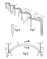
- a first embodiment is illustrated of a soil and water-retaining wall in accordance with the invention.
- This wall is composed of completely prefabricated load-bearing uprights, each of which consists of a steel broad flange girder or H-section 1, and intervening cylindrically curved shells 2, which are formed in the soil of concrete or similar hardenable material and which connect on both sides to the H-sections 1, without joints in a soil-tight and watertight fashion.
- the ends of the shells 2 connect with the H-sections 1 in the corner between the web 3 of the section 1 and a flange 4 located at the side of the excavation.
- the shells 2 are made without reinforcement.
- a method is elucidated for forming the soil and water-retaining wall as shown in fig. 1.
- the H-sections 1 are introduced into the soil at a mutual spacing of for example 2.00 metres, for example by means of ramming, vibrating or preliminary drilling.
- a steel forming mould 5 is downwardly fed in the soil which mould has practically the same shape and dimensions as the shells 2 to be formed.
- this mould 5 is somewhat broader than the clearance between the webs 3 of consecutive H-sections 1.
- the mould 5 Prior to its introduction the mould 5 must therefore be bent inwards to some extent so that this mould can be clampingly introduced between the webs 3 of consecutive H-sections 1. This ensures that finally a hermetically sealed connection is obtained between the ends of the shells 2 and the H-sections 1, even if the actual position of the H-sections 1 should slightly deviate from the theoretically required position.
- this mould 5 is withdrawn again, and simultaneously a mix or mortar of concrete or the like is introduced into the cavity formed underneath the mould 5 and fills this cavity.
- This mortar is supplied from the top of the mould 5 via one or more channels (not shown) in the mould 5 to discharge apertures in the lower surface of the mould 5. This may take place under pressure or may be done by means of the filling channel having such height that the mortar will flow under the influence of gravity to the lower side of the mould 5.
- the H-sections 1 take up the loads in the vertical direction, whilst the shells 2 transfer the loads mainly in the horizontal direction to the nearest H-sections 1. This permits major savings in material which, together with the simple, completely mechanized method of working described hereinabove provide an extremely cheap soil and water-retaining wall.
- a thickness of approximately 10 mm is however inadequate to enable the mix or mortar of concrete or the like to be distributed uniformly over the distance between consecutive H-sections 1, which for example is 2 metres.
- the thickness of the shells 2 is made larger and may amount to 50-100 mm, for example.
- a thickness exceeding 100 mm is again not desirable because the mould 5, as has already been described hereinbefore, must to some extent be capable of elastic deformation.
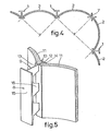
- the mould 5 has a slanting foot 6 on its lower side. This slant is such that the mould 5, under the influence of the soil resistance, has its ends pressed strongly into the corners between the web 3 of the neighbouring H-sections 1 and the flange 4 thereof which is located at the side of the excavation.
- the ends of the mould 5 and thus similarly the ends of a shell 2 formed by this mould enclose an angle of 45° with the plane which connects these ends (and which in the embodiment as shown in fig. 2 coincides with the plane through the flanges 4 of the H-sections 1, located at the side of the excavation).
- the ends of the mould 5 and thus similarly the ends of a shell 2 formed by this mould enclose an angle of 45° with the plane which connects these ends (and which in the embodiment as shown in fig. 2 coincides with the plane through the flanges 4 of the H-sections 1, located at the side of the excavation).
- Fig. 4 illustrates a corner portion of the soil and water-retaining wall shown in fig. 1.
- a cruciform section 7 has to be employed at the corner point, because here the abutting ends of the shells 2 must extend in line with each other.
- the load bearing uprights to consist of steel and of concrete or similar hardenable material.
- the shells 2 will extend into the soil to a smaller depth than the uprights.
- this method has the advantage that the work can be interrupted at any time, because the hardening of the material from which the shell 2 is formed does not impose any problem whatever during the formation in the soil of the next shell 2.
- the wall is required only as a temporary measure in the soil, it can be an advantage to withdraw the uprights again afterwards.
- the upright can initially be introduced further into the soil over a short distance, for example 10 cm, so as to reduce the adhesion between this upright and the ends of the abutting shells 2 made of concrete or similar hardenable material, whereafter the uprights can easily be withdrawn.
- the uprights at the point where they connect with the intervening shells 2, to be coated in advance with an anti-adhesion layer, which counteracts the adhesion of the concrete or similar hardenable material to the uprights.
- Fig. 5 shows a further embodiment of a soil and water-retaining wall in accordance with the present invention.
- the soil and water-retaining wall shown in fig. 1 there is a clear functional separation between the load bearing H-sections 1 and the intervening soil and water-retaining shells 2 of the wall, in the case of the wall shown in fig. 5 this separation no longer exists.
- the shells 2 rest on the flanges 4, facing the side of the excavation, of the load bearing H-sections 1. At the location where the soil moment is exerted on the wall these flanges 4 are subjected to tensile stresses and for this reason will be elongated.
- the curved shell 2, the ends of which are poured against these flanges 4, must thus follow this elongation.
- the concrete or similar hardenable material used for the shell 2 does not exhibit the same elasticity as the steel H-sections 1, it is possible for tensile cracks to occur in the shell material in the horizontal direction, so that under certain conditions the water tightness of the wall can deteriorate.
- the uprights consisting of steel sections 8 are made up of a tensile portion 9 which is located at the side of the excavation and a compression portion 10 which is located at the side of the soil mass.
- the ends of the intervening curved shells 11 connect with this compression portion 10 of the steel profiles 8.
- the compression portion 10 of the steel sections 8 consists of a web 12 and of two flanges 13, 14, whereby the ends of the curved shells 11 in cross section completely fill the space between the web 12 and the halves of the flanges 13, 14, located on the corresponding side, of the compression portion 10 of the steel sections 8.
- the tensile portion 9 of the steel sections 8 consists of a flange 15 and of a web 16 with trapezoidal recesses, which is welded to the flange 13 of the compression portion 10.
- the shells 11 function in the vertical direction as compression flanges of the overall wall and retain their function as an arch in the horizontal direction.
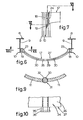
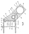
- Fig. 6, 7 and 8 schematically show a forming mould 17 which can be used for the formation in the soil of the curved shells 11 illustrated in fig. 5.
- this mould 17 has a lateral end portion which comprises a slide 18, by means of which the mould 17 is guided down or up along the compression portion 10 of the steel sections 8 which have been previously introduced into the soil.
- Each slide 18 is terminated by a runner 19 which projects downwards at the bottom, and which has a tapered end edge.
- This runner 19 fits into the compression portion 10 of the corresponding steel section 8 and serves to remove all the soil which is present between the flanges 13 and 14 and the web 12 of the compression portion 10 of the steel section 8.
- Each slide 18 extends over approximately the entire height of the mould 17 up to the runner 19 and is made up of two wear-resistant profiles 20 made of high-grade steel, which fit in slidable fashion over the ends of the flanges 13 and 14 of the compression portion 10 of the steel section 8 and which are connected with an intervening covering plate 21. Together with the wear-resistant profiles 20 and the compression portion 10 of the steel section 8 this covering plate 21 forms a channel 22 which is closed in its horizontal section.
- a hinge arrangement is connected with the slide 18 and consists of a housing 23 and a tube 24 which is rotatably mounted therein, but which is not capable of axial displacement; via an ample slot 25 in the housing 23 this tube is connected to the end of a steel plate member 26 which forms the core of the intervening thinner mould portion 27.
- the covering plate 21 Since the compression portion 10 of the steel section 8 is kept extremely clean in this manner, it is possible for the covering plate 21 to be provided with a plurality of sets of wheels 28, of which one set is shown in dot and dash lines in fig. 8. These sets of wheels 28 can roll over the web 12 of the compression portion 10 of the steel section 8. Naturally, instead of rolling over the web 12 of the compression section 10 of the steel section 8, the sets of wheels 28 may also roll over the inner side of the flanges 13 and 14. The use of the sets of wheels 28 considerably reduces the forces on the wear-resistant sections 20, while the friction between the mould 17 and the compression portions 10 of the steel sections 8 during the introduction of the mould 17 into the soil and during the raising of the mould 17, is considerably reduced.
- the plate member 26 is built up from sections, between which vertical tubes 30 extend, which serve for the supply of mortar of concrete or the like to the cavity formed underneath the mould 17 whilst this mould is being withdrawn, the said cavity always remaining filled in this manner.
- the thinner mould portion 27 is flexible again, so that the mould 17 can always be inserted subject to a certain stress, between two consecutive steel sections 8, even if these are not entirely in the correct position.
- the hinge constructions between the slides 18 and the plate member 26 make it easier to locate the mould 17 between consecutive steel sections 8.
- a vertical hinge 31 is provided (fig. 9). Such a hinge 31 always transmits the compressive force in the plane of the curved shell 11, but not the load component vertical thereto. The latter-mentioned load will result in a slight angular rotation at the location of the hinge 31.
- the hinge 31 shown in fig. 9 consists of a tube 32 which is filled with a mix or mortar 33 of the same type as that from which the curved shell 11 is made.
- the tube 32 once again connects without joint to the abutting portions of the corresponding curved shell 11.
- the hinge 31 extends over the entire height of the curved shell 11 and will generally be positioned approximately in the centre of this curved shell 11, although this is not essential.
- the tube 32 has a diameter which is somewhat larger than the thickness of the curved shell 11 at the point of the connection and should consist of a material to which the mortar does not adhere too strongly.
- the tube 32 can for example be made from plastic or be manufactured from steel coated with an anti-adhesion layer.
- both portions of the curved shell 11 can be subjected to a slight angular displacement around the tube 32. In this way stresses in the shell 11 which could result in fracture can be effectively prevented.
- Fig. 10 shows in an extremly schematic fashion a portion of a mould 34 which can be used for the formation of a curved shell 11 as shown in fig. 9.
- a steel tube 35 is fastened which has a diameter somewhat larger than the thickness of the thinner mould portion 27 at the point of connection.
- this tube 35 is closed at its lower side by a loose shoe 36 which remains behind in the soil after withdrawal of the mould 34.
- the tube 35 is used for the introduction into the soil of the tube 32 of the hinge 31. This tube 32 fits inside the tube 35.
- the mortar 33 Prior to the withdrawal of the mould 34 the mortar 33 is introduced from the top into the tube 32 and fills the tube 32 entirely.
- the tube 32 remains behind in the soil and the mortar used for forming the connecting portions of the curved shell 11 will make jointless contact with the external surface of the tube 32, thus providing a hermetic seal.
Landscapes
- Engineering & Computer Science (AREA)
- Structural Engineering (AREA)
- Life Sciences & Earth Sciences (AREA)
- General Life Sciences & Earth Sciences (AREA)
- Mining & Mineral Resources (AREA)
- Paleontology (AREA)
- Civil Engineering (AREA)
- General Engineering & Computer Science (AREA)
- Bulkheads Adapted To Foundation Construction (AREA)
- Retaining Walls (AREA)
Applications Claiming Priority (2)
| Application Number | Priority Date | Filing Date | Title |
|---|---|---|---|
| NL7900704 | 1979-01-30 | ||
| NL7900704A NL7900704A (nl) | 1978-10-16 | 1979-01-30 | Grond- en/of waterkerende wand; werkwijze voor het vormen van deze grond- en/of waterkerende wand; alsmede mal ingericht voor toepassing bij deze werkwijze. |
Publications (2)
| Publication Number | Publication Date |
|---|---|
| EP0022844A1 EP0022844A1 (en) | 1981-01-28 |
| EP0022844B1 true EP0022844B1 (en) | 1983-05-25 |
Family
ID=19832542
Family Applications (1)
| Application Number | Title | Priority Date | Filing Date |
|---|---|---|---|
| EP80900317A Expired EP0022844B1 (en) | 1979-01-30 | 1980-08-15 | Method for the formation of a soil and water-retaining wall, soil and water-retaining wall formed in accordance with this method and forming mould for the formation of this soil and water-retaining wall |
Country Status (5)
| Country | Link |
|---|---|
| US (1) | US4407612A (cg-RX-API-DMAC7.html) |
| EP (1) | EP0022844B1 (cg-RX-API-DMAC7.html) |
| JP (1) | JPS56500049A (cg-RX-API-DMAC7.html) |
| GB (1) | GB2058891B (cg-RX-API-DMAC7.html) |
| WO (1) | WO1980001582A1 (cg-RX-API-DMAC7.html) |
Families Citing this family (27)
| Publication number | Priority date | Publication date | Assignee | Title |
|---|---|---|---|---|
| US4545703A (en) * | 1983-02-09 | 1985-10-08 | Armco Inc. | Concrete faced bin wall |
| US4690588A (en) * | 1984-05-04 | 1987-09-01 | C-Lock Retention Systems, Inc. | Seawall |
| US4674921A (en) * | 1984-05-04 | 1987-06-23 | Berger Lawrence E | Seawall |
| US4621477A (en) * | 1985-07-18 | 1986-11-11 | Kinst Dennis I | Wall panel system |
| US4836718A (en) * | 1988-03-21 | 1989-06-06 | Schnabel Foundation Company | Earth retaining method and structure with improved corrosion protection and drainage |
| US4917543A (en) * | 1988-10-11 | 1990-04-17 | Dayco Products, Inc. | Wall system employing extruded panel sections |
| US5354149A (en) * | 1989-08-25 | 1994-10-11 | Barrier Member Containment Corp. | In-ground barrier system with pass-through |
| US5106233A (en) * | 1989-08-25 | 1992-04-21 | Breaux Louis B | Hazardous waste containment system |
| US5259705A (en) * | 1989-08-25 | 1993-11-09 | Breaux Louis B | Guide box assembly system for in-ground barrier installation |
| US5046898A (en) * | 1990-06-20 | 1991-09-10 | Mckinney Gary S | Retaining wall and building block therefor |
| US5435669A (en) * | 1992-09-11 | 1995-07-25 | Don Morin, Inc. | Laggin members for excavation support and retaining walls |
| NL9300245A (nl) * | 1993-02-08 | 1994-09-01 | Verstraeten Beheersmij Bv | Werkwijze voor het aanbrengen van een damwand in de bodem, alsmede een geprefabriceerd wandelement voor het toepassen van de werkwijze. |
| US5378088A (en) * | 1993-08-20 | 1995-01-03 | Foehrkolb; Nicholas A. | Retaining wall and method for forming, using segmented automobile tires |
| JP2754522B2 (ja) * | 1995-01-14 | 1998-05-20 | 建設基礎エンジニアリング株式会社 | 斜面安定化植生棚 |
| DE19526396C2 (de) * | 1995-07-19 | 2000-11-02 | Dyckerhoff Ag | Baugrubenverbau, Verfahren zu seiner Herstellung sowie Baustoffgemenge dafür |
| JP2787806B2 (ja) * | 1995-09-06 | 1998-08-20 | 建設基礎エンジニアリング株式会社 | 土留め擁壁 |
| JPH0988080A (ja) * | 1995-09-22 | 1997-03-31 | Kensetsu Kiso Eng Co Ltd | 土留め構造体 |
| ES2274661B1 (es) * | 2003-08-27 | 2008-04-01 | Emilio Garcia Tarrio | Sistema de contencion de terrenos. |
| US20050053429A1 (en) * | 2004-02-25 | 2005-03-10 | Davidsaver John E. | Modular retaining wall |
| US7628570B2 (en) * | 2004-02-25 | 2009-12-08 | Trueline, LLC | Modular retaining wall |
| KR100959300B1 (ko) | 2009-05-13 | 2010-05-26 | 이용호 | 가설 흙막이 구조물 |
| US8074406B2 (en) | 2010-04-29 | 2011-12-13 | Nick Ksenych | Modular secondary containment system |
| US9725873B2 (en) | 2013-11-12 | 2017-08-08 | Contech Engineered Solutions LLC | Secondary containment system |
| FR3041976B1 (fr) * | 2015-10-06 | 2017-11-24 | Soletanche Freyssinet | Quai portuaire constitue de parois voutees et de tirants plans |
| US11293161B2 (en) * | 2019-08-07 | 2022-04-05 | Structure Sight LLC | Retaining wall |
| US11891770B2 (en) * | 2021-04-12 | 2024-02-06 | Cmi Limited Co. | Catenary panel retaining wall |
| CN113529790B (zh) * | 2021-07-26 | 2022-08-26 | 中铁四局集团第五工程有限公司 | 一种地下行车道预应力侧墙及其张拉施工方法 |
Family Cites Families (10)
| Publication number | Priority date | Publication date | Assignee | Title |
|---|---|---|---|---|
| DE336452C (de) * | 1921-05-03 | Emil Pruess | Verfahren zum Gruenden von Gebaeuden in tragfaehigem Baugrunde | |
| US1423436A (en) * | 1920-06-01 | 1922-07-18 | Larsen Lee | Combined water-jet and suction apparatus and means for operating the same |
| FR972939A (fr) * | 1948-08-03 | 1951-02-05 | Perfectionnements aux dispositifs de quais, jetées et ouvrages analogues et à leurmode d'èxécution | |
| DE812463C (de) * | 1949-11-01 | 1951-10-31 | Gruen & Bilfinger A G | Bauwerke, wie Decken, Stuetzwaende u. dgl., aus Stahlbeton-Fertigbauteilen |
| FR1095729A (fr) * | 1954-03-15 | 1955-06-06 | Perfectionnements au mode de construction par colonnes et murs élémentaires | |
| FR1502707A (fr) * | 1966-07-11 | 1967-11-24 | Soletanche | Perfectionnements apportés aux murs de soutènement et à leur exécution |
| US3381483A (en) * | 1966-09-15 | 1968-05-07 | Charles K. Huthsing Jr. | Sea wall and panel construction |
| US3555830A (en) * | 1969-01-27 | 1971-01-19 | Pomeroy & Co Inc J H | Concrete wall structure and method |
| GB1424112A (en) * | 1973-02-07 | 1976-02-11 | Turzillo L A | Method and apparatus for producing sub-aqueous and other cast-in- place concrete structures in situ |
| US4050254A (en) * | 1975-08-13 | 1977-09-27 | International Engineering Company, Inc. | Modular structures, retaining wall system, and method of construction |
-
1980
- 1980-01-30 JP JP50041280A patent/JPS56500049A/ja active Pending
- 1980-01-30 WO PCT/NL1980/000003 patent/WO1980001582A1/en not_active Ceased
- 1980-01-30 US US06/212,091 patent/US4407612A/en not_active Expired - Lifetime
- 1980-01-30 GB GB8028402A patent/GB2058891B/en not_active Expired
- 1980-08-15 EP EP80900317A patent/EP0022844B1/en not_active Expired
Also Published As
| Publication number | Publication date |
|---|---|
| GB2058891A (en) | 1981-04-15 |
| GB2058891B (en) | 1983-03-09 |
| US4407612A (en) | 1983-10-04 |
| WO1980001582A1 (en) | 1980-08-07 |
| JPS56500049A (cg-RX-API-DMAC7.html) | 1981-01-16 |
| EP0022844A1 (en) | 1981-01-28 |
Similar Documents
| Publication | Publication Date | Title |
|---|---|---|
| EP0022844B1 (en) | Method for the formation of a soil and water-retaining wall, soil and water-retaining wall formed in accordance with this method and forming mould for the formation of this soil and water-retaining wall | |
| US6732483B1 (en) | Modular plastic pile systems and methods | |
| EP0264998B1 (en) | Method of manufacturing a foundation | |
| AU2004101058A4 (en) | Earth Retention and Piling Systems | |
| US20140270990A1 (en) | Precast concrete retaining wall | |
| EP0278936A1 (en) | An improved piling method | |
| WO2006057545A1 (en) | Tunnelling method using pre-support concept and an adjustable apparatus thereof | |
| US20030185634A1 (en) | Synthetic deformed bars and retaining walls | |
| EP0070659A1 (en) | Retaining wall and in situ method of construction | |
| CA1171675A (en) | Elongated underground construction having a uniform section and method of building this construction | |
| US7124545B1 (en) | Tilt-up panel and method | |
| CN208136903U (zh) | 一种预制预应力式地下连续墙 | |
| US4836718A (en) | Earth retaining method and structure with improved corrosion protection and drainage | |
| CN211816326U (zh) | 一种半h形抗滑桩和挡土板的联合支挡结构 | |
| US5871307A (en) | Pre-cast concrete panel wall | |
| CN210766868U (zh) | 用于既有重力式挡墙的加固结构 | |
| GB2076449A (en) | Process for the construction of an underground structure and a strucutre thus obtained | |
| AU2012202472B2 (en) | Earth Retention and Piling Systems | |
| US3854294A (en) | Method for producing a pile support arrangement | |
| US20080170913A1 (en) | Seawall connector for attachment of geogrid material | |
| CN210857186U (zh) | 一种预应力u型板桩 | |
| CA2171897C (en) | Pre-cast concrete panel wall | |
| CN113756378A (zh) | 一种现役建筑浅基础后置组合桩加固结构及其施工方法 | |
| EP0026782B1 (en) | Soil and water-retaining wall, composed of prefabricated plate elements | |
| CN215561875U (zh) | Tbm转场区域高架桥桥墩防护结构 |
Legal Events
| Date | Code | Title | Description |
|---|---|---|---|
| PUAI | Public reference made under article 153(3) epc to a published international application that has entered the european phase |
Free format text: ORIGINAL CODE: 0009012 |
|
| 17P | Request for examination filed |
Effective date: 19800904 |
|
| AK | Designated contracting states |
Designated state(s): FR |
|
| GRAA | (expected) grant |
Free format text: ORIGINAL CODE: 0009210 |
|
| AK | Designated contracting states |
Designated state(s): FR |
|
| ET | Fr: translation filed | ||
| PGFP | Annual fee paid to national office [announced via postgrant information from national office to epo] |
Ref country code: FR Payment date: 19831230 Year of fee payment: 5 |
|
| PLBE | No opposition filed within time limit |
Free format text: ORIGINAL CODE: 0009261 |
|
| STAA | Information on the status of an ep patent application or granted ep patent |
Free format text: STATUS: NO OPPOSITION FILED WITHIN TIME LIMIT |
|
| 26N | No opposition filed | ||
| PG25 | Lapsed in a contracting state [announced via postgrant information from national office to epo] |
Ref country code: FR Free format text: LAPSE BECAUSE OF NON-PAYMENT OF DUE FEES Effective date: 19890929 |
|
| REG | Reference to a national code |
Ref country code: FR Ref legal event code: ST |