US4917543A - Wall system employing extruded panel sections - Google Patents
Wall system employing extruded panel sections Download PDFInfo
- Publication number
- US4917543A US4917543A US07/255,810 US25581088A US4917543A US 4917543 A US4917543 A US 4917543A US 25581088 A US25581088 A US 25581088A US 4917543 A US4917543 A US 4917543A
- Authority
- US
- United States
- Prior art keywords
- panels
- wall
- wale
- members
- adjacent
- Prior art date
- Legal status (The legal status is an assumption and is not a legal conclusion. Google has not performed a legal analysis and makes no representation as to the accuracy of the status listed.)
- Expired - Fee Related
Links
- 239000000463 material Substances 0.000 claims abstract description 17
- 238000005452 bending Methods 0.000 claims description 9
- 239000002689 soil Substances 0.000 claims description 5
- 239000003000 extruded plastic Substances 0.000 claims 4
- 239000000945 filler Substances 0.000 claims 1
- 238000005728 strengthening Methods 0.000 abstract description 4
- 210000002105 tongue Anatomy 0.000 description 18
- 238000010276 construction Methods 0.000 description 4
- 238000001125 extrusion Methods 0.000 description 2
- 230000013011 mating Effects 0.000 description 2
- 230000007935 neutral effect Effects 0.000 description 2
- 230000000717 retained effect Effects 0.000 description 2
- XLYOFNOQVPJJNP-UHFFFAOYSA-N water Substances O XLYOFNOQVPJJNP-UHFFFAOYSA-N 0.000 description 2
- 230000004888 barrier function Effects 0.000 description 1
- 230000009977 dual effect Effects 0.000 description 1
- 230000003628 erosive effect Effects 0.000 description 1
- 230000014759 maintenance of location Effects 0.000 description 1
- 239000002184 metal Substances 0.000 description 1
- 239000004570 mortar (masonry) Substances 0.000 description 1
- 239000002023 wood Substances 0.000 description 1
Images


Classifications
-
- E—FIXED CONSTRUCTIONS
- E02—HYDRAULIC ENGINEERING; FOUNDATIONS; SOIL SHIFTING
- E02D—FOUNDATIONS; EXCAVATIONS; EMBANKMENTS; UNDERGROUND OR UNDERWATER STRUCTURES
- E02D5/00—Bulkheads, piles, or other structural elements specially adapted to foundation engineering
- E02D5/02—Sheet piles or sheet pile bulkheads
- E02D5/03—Prefabricated parts, e.g. composite sheet piles
- E02D5/04—Prefabricated parts, e.g. composite sheet piles made of steel
-
- E—FIXED CONSTRUCTIONS
- E02—HYDRAULIC ENGINEERING; FOUNDATIONS; SOIL SHIFTING
- E02D—FOUNDATIONS; EXCAVATIONS; EMBANKMENTS; UNDERGROUND OR UNDERWATER STRUCTURES
- E02D29/00—Independent underground or underwater structures; Retaining walls
- E02D29/02—Retaining or protecting walls
- E02D29/0258—Retaining or protecting walls characterised by constructional features
- E02D29/0266—Retaining or protecting walls characterised by constructional features made up of preformed elements
-
- E—FIXED CONSTRUCTIONS
- E02—HYDRAULIC ENGINEERING; FOUNDATIONS; SOIL SHIFTING
- E02D—FOUNDATIONS; EXCAVATIONS; EMBANKMENTS; UNDERGROUND OR UNDERWATER STRUCTURES
- E02D5/00—Bulkheads, piles, or other structural elements specially adapted to foundation engineering
- E02D5/02—Sheet piles or sheet pile bulkheads
- E02D5/03—Prefabricated parts, e.g. composite sheet piles
- E02D5/04—Prefabricated parts, e.g. composite sheet piles made of steel
- E02D5/08—Locking forms; Edge joints; Pile crossings; Branch pieces
-
- E—FIXED CONSTRUCTIONS
- E02—HYDRAULIC ENGINEERING; FOUNDATIONS; SOIL SHIFTING
- E02D—FOUNDATIONS; EXCAVATIONS; EMBANKMENTS; UNDERGROUND OR UNDERWATER STRUCTURES
- E02D5/00—Bulkheads, piles, or other structural elements specially adapted to foundation engineering
- E02D5/66—Mould-pipes or other moulds
- E02D5/68—Mould-pipes or other moulds for making bulkheads or elements thereof
-
- E—FIXED CONSTRUCTIONS
- E02—HYDRAULIC ENGINEERING; FOUNDATIONS; SOIL SHIFTING
- E02D—FOUNDATIONS; EXCAVATIONS; EMBANKMENTS; UNDERGROUND OR UNDERWATER STRUCTURES
- E02D5/00—Bulkheads, piles, or other structural elements specially adapted to foundation engineering
- E02D5/74—Means for anchoring structural elements or bulkheads
Definitions
- This invention relates to retaining walls and wall systems and more particularly to such walls and systems, including panels of extruded polymeric material, for use as sea walls, retainers, revetments, sound barriers, construction panels, room dividers, building walls, floors, ceilings, and the like.
- Sinusoidal or corrugated sheets have been mounted in facing relation and connected or joined by tie rods, and the spaces therebetween have been filled with concrete or mortar to provide a water-tight joint, to form a revetment, as shown in Schneller, U.S. Pat. No. 3,247,673 of April 26, 1966.
- Sinusoidal or corrugated panel sections have been used to make up retaining walls or sea walls, with wale elements on a front surface tied back to anchors, as shown in a number of prior patents.
- Caples U.S. Pat. No. 1,947,151 of Feb. 13, 1934 shows panel sections formed with interconnecting locking vertical edges in alternating inwardly and outwardly directed portions to form a sinusoidal wall.
- the interlocking ends are identical.
- Frederick, U.S. Pat. No. 3,822,557 of July 9, 1974 one panel vertical edge is formed with a tongue and the opposite panel vertical edge is formed with a groove proportioned to receive the tongue of an adjacent panel.
- FIGS. 7 and 8 also show opposed facing pairs of corrugated sections in which the spaces therebetween may be filled with concrete to form a revetment.
- wale brackets or wale elements in combination with panel-type sea walls or retainer walls.
- Berger, Schnabel, Jr. and Caples show wale elements in longitudinal alignment.
- Schnabel, Jr., U.S. Pat. No. 3,541,798 of Nov. 24, 1970 shows individual longitudinally spaced wale elements along the wall front face.
- the wale elements receive tie-back rods, which rods extend through or between the panels to suitable anchors.
- This invention relates to retaining wall systems particularly adapted for use as sea walls or the like, which incorporate improvements and advantages not shown in the above-identified prior art.
- a principal part of the wall system comprises a plurality of individual panels, preferably formed by the extrusion of polymeric material, such as PVC, or the like.
- each of the panels may be of essentially identical construction, such as with continuous grooves formed along the opposed or lateral edges, for engagement with interfitting tongues formed on the opposed edges of intervening interlocking elements.
- one panel may be formed with grooves along the lateral edges and an adjacent panel may be formed with tongues along its lateral edges proportioned to be engaged in the groove of an adjacent panel.
- the panels are formed with integral ribs which extend along the length of the panel.
- the ribs may be for strength and/or acoustical purposes, and are formed on the inside or concavely curved surface of the panel.
- the invention further comprises an improvement in wale members and in the interconnection of the wale members which add substantially to the overall strength of the wall.
- the wale members which are generally channel or box-shaped in cross-section, are formed with interlocking longitudinally extending upper and lower walls or surfaces. When assembled, the end portions of the wale members mutually overlap and interlock with each other. The bending moments of one wale member are transmitted to the adjacent laterally extending and interlocking wale member, thereby substantially adding to the overall strength of the wall.
- the wall systems of the invention are particularly adapted for use as permanent concrete forms, in forming revetments.
- the arcuately curved sections or panels of one wall section are laterally offset from the facing arcuately curved sections of an adjacent wall section.
- the panels of these wall sections are suitably spaced and joined, such as by tie rods, they form permanent forms between which concrete may be placed or poured to form a strong revetment.
- each of the panels may be identical and linked or joined in edge-to-edge alignment by suitable intervening connector elements.
- the connector elements provide versatility and permit the panels sections to be arranged in varying configurations, and also provide for defined wall corners or angles, as required.
- the panels making up the wall systems of this invention have a convex surface and an opposite concave surface with the concave surface having one or more integral ribs thereon.
- a plurality of ribs in the form of three ribs are uniformly spaced apart on the concave side and extend transversely to a common depth.
- the panels may be configured in such a way as to eliminate the need for intervening connectors.
- the panel edges may be configured in the form of alternating tongues and grooves to permit the panels to be directly interlocked one to the other.
- Such panels may be formed either with tongues or grooves at the vertical edges, and then alternated for interlocking, or the panels may be formed with the tongue along one edge and a groove along the other edge, eliminating the need for using alternate panels for interlocking.
- Panels making up a wall of this invention may be suitably attached to posts and supporting rails, where the rails may take the place of the interconnected and interlocked wale members, where maximum strength may not be required.
- Such a construction may have advantage in the erection of a sound deflecting wall, construction wall, temporary wall, or a retaining wall where wale elements and tiebacks may not be required. Also, such arrangement has the advantage of exposing the face of the wall, free of wale members.
- the panels need not be run vertically. In some instances, it may be desirable to run the panels horizontally between supporting posts. In such instance, the advantage of the interlocking panels or interlocking connector elements may be enjoyed in a low-cost and easy-to-erect wall system.
- Another object of the invention is the provision of a wall, as outlined above, incorporating wale members which longitudinally interlock with each other along overlapping end portions thereof.
- a further object of the invention is the provision of a wall, as outlined above, in which individual panels are formed with generally vertically extending ribs formed on the concave side of the panel.
- Another object of the invention is the provision of a panel for use with a plurality of identical panels in making up a sea wall or a retainer wall or the like, in which the panel is formed of extruded material and is arcuately shaped to provide high strength against buckling and bending.
- Another object of the invention is the provision of a wall system utilizing a plurality of individual panels, and supported and strengthened by wale members, in which the wale members are longitudinally interlocked at the end portions thereof, one to another, in overlapping relation.
- a still further object of the invention is the provision of a wall system, useful as a revetment, in which a pair of walls are positioned in spaced, opposed relation, in which curved panels have the concave sides thereof opposed and facing each other, joined by tie rods, and defining a space into which concrete may be poured to form a completed wall system.
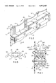
- FIG. 1 is a perspective fragmentary view of a retaining wall system made in accordance with a first embodiment of this invention used as a sea wall;
- FIG. 2 is a vertical section through the wall looking generally along the line 2--2 of FIG. 1;
- FIG. 3 is an enlarged fragmentary perspective view of a portion of the retaining wall of FIGS. 1 and 2, showing the interconnected wale members;
- FIG. 4 is an enlarged fragmentary vertical section through one of the wale members showing, in elevation, a longitudinally interconnected wale member, looking generally along the line 4--4 of FIG. 3;
- FIG. 5 is a fragmentary end view of one form of a connector element employed with this invention.
- FIG. 6 is an end view of a corner-type connector element
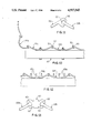
- FIG. 7 is a fragmentary view of a plurality of panels in which the curvature of alternate panels are reversed, using the connector member of FIG. 5;
- FIG. 8 is a fragmentary detail showing how the connector element of FIG. 5 is employed when the curvature of adjacent panels is reversed;
- FIG. 9 is a top plan view, of another preferred embodiment of a wall system in which the concave surface of the panel is provided with a plurality of transversely extending strengthening ribs.
- the panels of the embodiment of FIG. 9 are particularly adapted to employ the interlocking connector elements of FIGS. 5, 6 and 8;
- FIG. 10 is a fragmentary top view of a modified form of the wall of this invention employing alternate panels formed either with tongues or grooves, such that tongued panels are alternated with grooved panels, and further showing a modified panel for forming a corner;
- FIG. 11 is an enlarged fragmentary view showing the interconnection of a pair of adjacent panels made according to the embodiment of FIG. 10;
- FIG. 12 is a fragmentary plan view of a modified form of the panel of FIGS. 10 and 11 incorporating strengthening ribs on the concave surface thereof;
- FIG. 13 is an enlarged end view of a interlocking connector element formed with transversely spaced grooves permitting the interconnection of an adjacent pair of the tongue portions of panels constructed according to the embodiment of FIGS. 9 and 10;
- FIG. 14 is a fragmentary perspective front view of a sea wall or retaining wall according to the embodiment of FIGS. 1 or 3, in which supporting posts and rails are mounted on the land side of the wall;
- FIG. 15 is a fragmentary perspective of a wall and supporting wale members made in accordance with the embodiment of FIG. 9;
- FIG. 16 is an enlarged fragmentary plan view showing a preferred manner of interconnecting panels of the embodiments of FIGS. 9 and 15 to a wale member.
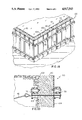
- FIG. 17 is a fragmentary perspective view, somewhat similar to FIG. 14, showing the use of the individual panels running horizontally of the posts to form a wall;
- FIG. 18 is a perspective view of a further preferred embodiment of a wall system in accordance with this invention in which a pair of wall sections are positioned in spaced-apart relation, providing forms between which concrete may be poured to form a revetment;
- FIG. 19 is a fragmentary enlarged section taken generally the along the line 19--19 of FIG. 18.
- a retainer wall system in the form of a sea wall is shown at 20 in FIGS. 1-4 as including a plurality of essentially identical extruded panels 22 formed of polymeric material, such as PVC.
- the wall 20 forms a retainer for the soil 23 on the back side of the panels 22 with the sea 24 at the front surface.
- the panels 22, as shown in FIG. 2 extend vertically with lower ends received in the subsoil below the lower level of the water at the shoreline.
- the panels 22 are joined in edge-to-edge relation by extruded interlocking connector elements 25, also formed of the polymeric material, such as PVC, as shown in FIG. 5.
- the individual panels 22 each have an arcuately curved body 26 which, over the major transverse extent, is formed of uniform thickness, such as by extrusion, to form a convex surface on one side and a concave surface on the other side.
- the arcuate portion of the body has the shape of a segment of a cylinder.
- the panel 22 terminates along vertical margins or edges which form connector or locking portions, either in the form of locking tongues or tongue-receiving grooves. In the embodiment as shown in FIGS. 1-3, the panels 22 have widened vertical edges which define interlocking grooves 27, as best shown in FIG. 5.
- the adjacent facing grooves 27 of adjacent panels are interconnected by the interlocking connector element 25, as shown in FIG. 5.
- the connector element 25 is formed with a body 28 defining a pair of oppositely facing identical tongues 29 which extend along the length of the element.
- the tongues 29 are proportioned to be received in an associated adjacent groove 27 of a panel 22.
- a plurality of the panels and connectors may be assembled in generally vertical relation, to form the wall 20 as shown in FIG. 1, with the respective concave panel sides thereof facing the land mass to be retained, and the convex side facing the water, in the case of a sea wall.
- connector elements 25 permits versatility in the use of the panels 22 to make up a wall.
- a right-angle connector element 25a of FIG. 6 may be used to form a corner, as shown in FIGS. 1 and 6.
- the connector or locking portions are at about 90° to each other.
- connector elements 25 and the associated panel edge slots 27 have a neutral orientation, thereby permitting alternate panels 22 to be reversed, as illustrated in FIGS. 7 and 8.
- Such an arrangement may be desirable where the panels are to be used to make an exposed wall, to provide a decorative appearance, or introduce variety, where maximum strength in one direction only is not a paramount consideration.
- the assembled panels 22 and connector elements 25 are retained and supported by a plurality of transversely extending wale members 30.
- the wale members 30 may also be formed of extruded polymeric material, such as PVC, and are received against the outer convex surfaces 31 of the panels 22.
- the wale members 30 receive conventional tie bolts or rods 32 therethrough, also preferably made of suitable polymeric material, such as PVC.
- the wale members may be of any convenient length, preferably spanning a plurality of assembled panels 22 and connector elements 25.
- the wale members 30 are channel-shaped to form a hollow interior closed by a transversely extending vertical back wall 33, a horizontal top wall 34, and a parallel horizontal bottom wall 35.
- the tie bolt 32 extends through the back wall 33 and the hollow interior between the top and bottom walls 34, 35 and through the body 26 of the adjacent panel, so that the member abuts the adjacent convex panel sides 31 at the inner edges of the top and bottom walls.
- the top and bottom walls of the wale members 30 are provided with means for mutually interlocking the overlapping end portions of adjacent members, so that the loads and bending moments applied to one wale member may, in part, be transferred to the overlapping member.
- the interlocking means is in the form of interfitting flange portions formed respectively on the top and bottom walls.
- the top wall 34 is formed with a neck 35 terminating in a pair of flanges 36 which extend parallel to the wall 34 and which define flange-receiving slots 36a with the outer surface of the wall 34.
- the flanges 36 on the neck 35 terminate at square or flat ends 36b which are spaced apart a distance less than the depth of the member as measured from the outer surface 33a of the back wall to the open side of the member 30.
- the outside upper surface 36c is flat and is parallel to the opposed inside surface 34a of the top wall.
- the bottom wall 35 also has a flat inside surface 35a parallel to the surface 34a.
- a slot 37 is formed by the outside wall surface 35b and by a pair of inwardly-directed flanges 38.
- the flanges also terminate in opposed edges 37a which are flat and normal to the surface 35b.
- the outer flange 38a extends inwardly from an extension 33a of the outer wall, while the inner flange 38b extends inwardly from a connector segment 39, the inner surface of which abuts the panel surface 31.
- the vertical spacing of the slots 37 as defined by the flanges 38 is no more than sufficient to receive and form a tight fit with the flanges 36.
- the wale members 30 may thus be considered as having a tongue form on one wall and a groove on the opposite wall, in which the grooves are proportioned to receive the tongues of an overlapping member 30.
- the overlapping end portions of the wale members are firmly interlocked in a common plane with respect to the adjacent convex surfaces 31 of the panels, one above the other. In this manner, bending moments and loads applied to or carried at one location on the wall 20 are distributed transversely to other locations which would not otherwise see such moments or loads.
- Either a single row of wale members may be used or two or more such rows may be employed, as shown in FIGS. 1 and 2.
- the tie bolts 32 of either or both such rows may be formed with eyes 40 and tied back by rods or cables 42 to ground anchors 44, as shown in FIG. 2. Again, the rods, cables and ground anchors may be formed of polymeric material.
- FIGS. 10-12 illustrate another preferred embodiment of the wall system in which individual panels 22b are formed with only tongues 50 along the opposite marginal edges, and mating panels 22c are formed with mating grooves 52 along the marginal edges.
- the wale members 30 previously described may be used with the wall panels of the embodiment, as shown in FIG. 10.
- the panels 22b and 22c are alternated and interlocked directly to each other as they are inserted into the wall. Corners may be formed by a corner panel 22d specially adapted for this purpose.
- FIG. 13 illustrates a connector element 60 particularly adapted to connect the tongues of adjacent panels 22b without the use of an adjoining panel 22c.
- the opposite grooves 62 are not on a neutral axis as in the elements 25, but are angled to receive the correspondingly angled tongues 50 of the panels 22b.
- the panel 22e is extruded with a plurality of integral ribs 65 extending laterally from its concave surface 66. While three ribs are shown, the ribs may be greater or fewer in number within the scope of this invention.
- the ribs 65 may extend laterally to a common depth corresponding to a chord line across the open side of the panel 22e.
- interlocking panels as shown in FIG. 10 and described above may also be provided with strengthening or acoustical ribs 65a on the panels 22f and 22g of FIG. 12. In other respects, these panels may be identical to panels 22b and 22c, respectively.
- FIG. 14 it may be desirable to support the wall on support posts and rails on the convex side 31 of the panels.
- the horizontal rail members 70 may be the wale members 30 as previously described, and in other instances, may advantageously be simple wood or metal support rails, secured to the wall panels by bolts 72.
- the rails 70 may be secured to vertical posts 75 driven into the ground.
- the arrangement of FIG. 14 provides versatility in such instances where ground anchors are not required, such as for free-standing walls, sound deflector walls, privacy enclosures and the like.
- the wall systems of FIG. 14 presents the concave side of the panels to view, free of wale members or rails.
- the panels 22 and connector elements 25 are positioned horizontally one above the other and are connected by suitable bolts to vertical posts 75.
- the wall systems of the present invention are particularly adapted to form very strong revetments, such as for sea walls and the like.
- a dual wall system is illustrated generally at 100 in FIGS. 18 and 19.
- the wall system 100 includes an inner wall section 102 and an essentially identical outer wall section 104.
- Each of the wall sections 102, 104 may be made essentially in accordance with the teachings directed to the wall 20 of FIGS. 1-5 herein, except that the panels 22 of the individual wall sections 102 and 104 are positioned in spaced-apart facing relation with the concave surfaces of the panels positioned generally opposite each other.
- the panels of the wall sections may be tied together by common transversely extending tie rods 105 as illustrated in FIG.
- the tie rods 105 may, like the tie bolts 32, be connected back to anchors by cables 42 in the manner illustrated in FIG. 2.
- the wall sections 102 and 104 define an open space therebetween which may be filled with concrete 110, as shown in FIG. 19. In this manner, the wall sections 102 and 104 form permanent forms for the concrete 110, thereby providing an erosion resistance and environmentally safe surface for the concrete while the concrete synergistically provides rigidity to produce a structure such as a revetment.
- this invention provides versatile wall systems by means of which a plurality of individual extruded panels may be connected or joined together, with wale members, to form strong and effective retaining walls, sea walls, and the like.
Landscapes
- Engineering & Computer Science (AREA)
- Structural Engineering (AREA)
- Life Sciences & Earth Sciences (AREA)
- General Life Sciences & Earth Sciences (AREA)
- Mining & Mineral Resources (AREA)
- Paleontology (AREA)
- Civil Engineering (AREA)
- General Engineering & Computer Science (AREA)
- Chemical & Material Sciences (AREA)
- Composite Materials (AREA)
- Environmental & Geological Engineering (AREA)
- Revetment (AREA)
Abstract
Description
Claims (18)
Priority Applications (2)
| Application Number | Priority Date | Filing Date | Title |
|---|---|---|---|
| US07/255,810 US4917543A (en) | 1988-10-11 | 1988-10-11 | Wall system employing extruded panel sections |
| CA002000403A CA2000403A1 (en) | 1988-10-11 | 1989-10-10 | Wall systems employing extruded panel sections |
Applications Claiming Priority (1)
| Application Number | Priority Date | Filing Date | Title |
|---|---|---|---|
| US07/255,810 US4917543A (en) | 1988-10-11 | 1988-10-11 | Wall system employing extruded panel sections |
Publications (1)
| Publication Number | Publication Date |
|---|---|
| US4917543A true US4917543A (en) | 1990-04-17 |
Family
ID=22969971
Family Applications (1)
| Application Number | Title | Priority Date | Filing Date |
|---|---|---|---|
| US07/255,810 Expired - Fee Related US4917543A (en) | 1988-10-11 | 1988-10-11 | Wall system employing extruded panel sections |
Country Status (2)
| Country | Link |
|---|---|
| US (1) | US4917543A (en) |
| CA (1) | CA2000403A1 (en) |
Cited By (75)
| Publication number | Priority date | Publication date | Assignee | Title |
|---|---|---|---|---|
| US5125765A (en) * | 1991-08-26 | 1992-06-30 | Verble Patrick R | Seawall construction |
| US5190413A (en) * | 1991-09-11 | 1993-03-02 | The Neel Company | Earthwork system |
| US5244316A (en) * | 1991-05-17 | 1993-09-14 | Wright William M | Borer-resistant waterfront retaining bulkhead |
| US5259705A (en) * | 1989-08-25 | 1993-11-09 | Breaux Louis B | Guide box assembly system for in-ground barrier installation |
| US5292208A (en) * | 1992-10-14 | 1994-03-08 | C-Loc Retention Systems, Inc. | Corner adapter for corrugated barriers |
| US5354149A (en) * | 1989-08-25 | 1994-10-11 | Barrier Member Containment Corp. | In-ground barrier system with pass-through |
| US5360293A (en) * | 1989-08-25 | 1994-11-01 | Barrier Member Containment Corporation | In-ground barrier member interlocking joint and seal system |
| US5368414A (en) * | 1991-07-19 | 1994-11-29 | Miller; Vincent G. | Method and system for rehabilitating a bulkhead |
| US5400563A (en) * | 1991-03-26 | 1995-03-28 | Marylyn House | Combination column and panel barrier system and method of construction |
| GB2283039A (en) * | 1993-09-24 | 1995-04-26 | Bank Master Systems Limited | Piling |
| US5435669A (en) * | 1992-09-11 | 1995-07-25 | Don Morin, Inc. | Laggin members for excavation support and retaining walls |
| US5471811A (en) * | 1989-05-04 | 1995-12-05 | Marylyn House | Combination traffic barrier and retaining wall and method of construction |
| GB2290819A (en) * | 1994-06-28 | 1996-01-10 | Plastic Piling Ltd | Shutter piling |
| US5494379A (en) * | 1993-08-30 | 1996-02-27 | The Reinforced Earth Company | Earthen work with wire mesh facing |
| FR2732375A1 (en) * | 1995-03-29 | 1996-10-04 | Marchand Eric Camille | Repairing and realigning device for damaged upper sections of sheet piling along keys, riverbanks or platforms |
| US5588786A (en) * | 1989-05-04 | 1996-12-31 | Marylyn House | Combination retaining wall and method of construction |
| US5626807A (en) * | 1995-07-06 | 1997-05-06 | Tri-Seal International, Inc. | Method for making retaining wall members |
| US5658098A (en) * | 1995-07-26 | 1997-08-19 | Hercules Manufacturing, Inc. | Polymeric retaining wall building block |
| US5765970A (en) * | 1996-06-17 | 1998-06-16 | Fox; James C. | Plastic retaining wall construction |
| US5772186A (en) * | 1997-04-22 | 1998-06-30 | Parker; Alton B. | Fence employing uniform L-shaped flat sided galvanized steel posts and flat sided rails |
| US5797706A (en) * | 1993-06-24 | 1998-08-25 | Societe Civile Des Brevets Henri Vidal | Earth structures |
| US5902074A (en) * | 1996-11-05 | 1999-05-11 | Berkley; David M. | Apparatus and method for stabilizing sloped embankments |
| USD415580S (en) | 1996-02-23 | 1999-10-19 | Roller Drome, Llc | Wall panel |
| US6033155A (en) * | 1998-03-09 | 2000-03-07 | Materials International, Inc. | Reinforced structure panel for forming barrier walls |
| US6135675A (en) * | 1997-12-19 | 2000-10-24 | Northstar Vinyl Products Llc | Sheetpile system including full plastic exterior |
| US6168351B1 (en) * | 1997-04-30 | 2001-01-02 | Anchor Wall Systems, Inc. | Retaining wall anchoring system |
| USD440327S1 (en) | 1996-02-23 | 2001-04-10 | Roller Drome, Llc | Wall panel |
| US6299386B1 (en) * | 1999-06-09 | 2001-10-09 | R. John Byrne | Method and apparatus for a shoring wall |
| RU2181813C1 (en) * | 2001-04-25 | 2002-04-27 | Фоменков Александр Алексеевич | Sheet pile |
| RU2181814C1 (en) * | 2001-07-11 | 2002-04-27 | Фоменков Александр Алексеевич | Sheet pile |
| US6454491B1 (en) | 1998-11-24 | 2002-09-24 | Mark Wayne | Portable seawall system |
| WO2002086243A1 (en) * | 2001-04-25 | 2002-10-31 | Aleksandr Alekseevich Fomenkov | Grooved sheet pile and method for production thereof |
| US6588732B1 (en) * | 1998-07-07 | 2003-07-08 | Peter B. Caceres | Fiberglass fencing system |
| WO2003064773A1 (en) | 2002-02-01 | 2003-08-07 | Christopher Gerard Macdonald | Sheet pile |
| US20040013476A1 (en) * | 2002-07-19 | 2004-01-22 | Weyant Shane E. | Wale and retaining wall system |
| US20040126193A1 (en) * | 2002-11-01 | 2004-07-01 | Jeff Moreau | Carbon fiber re-enforced composite sheet piling segments |
| US20040131429A1 (en) * | 1997-04-30 | 2004-07-08 | Rainey Thomas L. | Retaining wall anchoring system |
| US20040141815A1 (en) * | 2002-11-01 | 2004-07-22 | Jeff Moreau | Fiber re-enforcement of joints and corners of composite sheet piling segments |
| US20040208702A1 (en) * | 2003-04-21 | 2004-10-21 | Buchanan Gregory J. | Reinforced interlocking retention panels |
| US20050042417A1 (en) * | 2003-08-21 | 2005-02-24 | Cmi Limited Company | Open network structural members |
| US20050042038A1 (en) * | 2003-08-21 | 2005-02-24 | Irvine John E. | Sheet pile for forming barrier walls |
| US20050053429A1 (en) * | 2004-02-25 | 2005-03-10 | Davidsaver John E. | Modular retaining wall |
| US20050211449A1 (en) * | 2004-03-12 | 2005-09-29 | Clark Equipment Company | Automated attachment vibration system |
| US20050271480A1 (en) * | 2004-06-04 | 2005-12-08 | Irvine John E | Anchor system for use in forming barrier walls |
| US20060032186A1 (en) * | 2004-07-30 | 2006-02-16 | Enzo Vardaro | Adjustable wall system |
| US20070077129A1 (en) * | 2003-10-14 | 2007-04-05 | Aloyse Hermes | King pile for a support wall curtain |
| NL1030530C2 (en) * | 2005-11-25 | 2007-05-29 | Halteren Infra B V Van | Removable anchor. |
| US20070147962A1 (en) * | 2005-12-22 | 2007-06-28 | Rob Wendt | Building made of sheet piles |
| US20070217870A1 (en) * | 2004-02-25 | 2007-09-20 | Formtech Enterprises, Inc. | Modular retaining wall |
| US7278803B1 (en) * | 2006-09-05 | 2007-10-09 | Jeff M Moreau | Corrugated asymmetrical retaining wall panel |
| RU2315153C1 (en) * | 2006-08-09 | 2008-01-20 | Сергей Федорович Налимов | Sheet pile |
| RU2315152C1 (en) * | 2006-08-09 | 2008-01-20 | Сергей Федорович Налимов | Sheet pile |
| US20100044663A1 (en) * | 2008-08-22 | 2010-02-25 | Ptacek James A | Interlocking fencing system |
| US20100074698A1 (en) * | 2008-09-25 | 2010-03-25 | Terra Shield, Llc | Sheet pile for the subterranean support of underground conduits |
| US20100251649A1 (en) * | 2008-08-15 | 2010-10-07 | Smart Slope, Llc | Retaining Wall System |
| US20100263892A1 (en) * | 2009-04-16 | 2010-10-21 | Hercules Machinery Corporation | Method and apparatus for facilitating the subterranean support of underground conduits having a fixed insertion axis |
| US20110008111A1 (en) * | 2009-07-10 | 2011-01-13 | Hercules Machinery Corporation | Apparatus for inserting sheet pile having an independently adjustable insertion axis and method for using the same |
| US8033758B1 (en) * | 2007-08-02 | 2011-10-11 | Darryl Scott Burkett | Apparatus and method for making a polymer sheet piling wall |
| US8074406B2 (en) | 2010-04-29 | 2011-12-13 | Nick Ksenych | Modular secondary containment system |
| RU2446252C2 (en) * | 2010-07-09 | 2012-03-27 | Геннадий Иванович Томарев | Piling wall and device for pile pressing |
| RU2475592C2 (en) * | 2011-05-24 | 2013-02-20 | Егор Игоревич Кириенко | Sheet pile wall |
| FR3047262A1 (en) * | 2016-02-01 | 2017-08-04 | Thierry Marquet | MODULAR DEVICE FOR FORMING A GROUND ANCHOR POINT |
| US9725873B2 (en) | 2013-11-12 | 2017-08-08 | Contech Engineered Solutions LLC | Secondary containment system |
| US9932753B1 (en) * | 2017-06-14 | 2018-04-03 | N. Eric Knudsen | Fence panel systems and methods |
| US9938684B1 (en) * | 2017-05-31 | 2018-04-10 | Han Ju KANG | Guide assembly for guiding a casing used in forming a sheathing wall in a ground and a method for forming a sheathing wall in a ground using the same |
| US10145076B2 (en) * | 2016-08-12 | 2018-12-04 | Pnd Engineers, Inc. | Sheet pile bulkhead systems and methods |
| US20180354715A1 (en) * | 2012-10-11 | 2018-12-13 | Allied Steel | Secondary containment |
| WO2019113665A1 (en) * | 2017-12-12 | 2019-06-20 | Construtora E Incorporadora Pierozan Ltda Me | Construction system |
| US10633176B2 (en) | 2018-02-14 | 2020-04-28 | 2C Enviro Inc. | Fluid containment device |
| NL2022393B1 (en) * | 2019-01-14 | 2020-08-14 | Key Staal B V | Assembly of a retaining wall, at least two elongated anchoring elements and a purlin beam |
| US11105199B2 (en) * | 2019-09-11 | 2021-08-31 | Square Cut Systems, LLC | System and method for supporting sidewalls or ribs in coal mines |
| JP2022045376A (en) * | 2020-09-09 | 2022-03-22 | 鹿島建設株式会社 | Earth retaining structure and earth retaining method |
| JP2022102269A (en) * | 2020-12-25 | 2022-07-07 | 鹿島建設株式会社 | Earth retaining structure |
| US20220325494A1 (en) * | 2021-04-12 | 2022-10-13 | Cmi Limited Co. | Catenary panel retaining wall |
| RU2791212C1 (en) * | 2022-09-02 | 2023-03-06 | Анатолий Григорьевич Жириков | Quick-mounting modular sheet pile construction for flood protection (variants) |
Citations (20)
| Publication number | Priority date | Publication date | Assignee | Title |
|---|---|---|---|---|
| US901241A (en) * | 1903-11-06 | 1908-10-13 | Edward A Bern | Metal piling. |
| US972059A (en) * | 1910-05-11 | 1910-10-04 | Thomas Curtis Clarke | Temporary wall. |
| US1032109A (en) * | 1910-11-01 | 1912-07-09 | Lackawanna Steel Co | Junction member for steel sheet-piling. |
| US1067489A (en) * | 1913-02-24 | 1913-07-15 | James W Sederquist | Interlocking sheet-piling. |
| US1371709A (en) * | 1920-07-06 | 1921-03-15 | Stockfleth John | Sheet-piling construction |
| US1422821A (en) * | 1915-07-07 | 1922-07-18 | Lackawanna Steel Co | Sheet-piling wall construction |
| US1918886A (en) * | 1926-05-31 | 1933-07-18 | Dougree Marihaye Sa | Sheet pile |
| US1947151A (en) * | 1932-12-27 | 1934-02-13 | William G Caples | Sheet-metal-piling wall structure |
| US2099542A (en) * | 1936-01-31 | 1937-11-16 | Stevens Edwin Fenton | Interlocking steel sheet piling |
| US2698931A (en) * | 1945-05-09 | 1955-01-04 | Stanley N Van Voorhis | Synchronizer for indicators |
| US3247673A (en) * | 1961-06-06 | 1966-04-26 | Nat Gypsum Co | Laminated retaining wall and method of constructing same |
| US3420065A (en) * | 1967-03-06 | 1969-01-07 | Edward J Holl | Adjustable bracing means for vertically disposed earth-shoring planking |
| US3541798A (en) * | 1969-04-18 | 1970-11-24 | Harry Schnabel Jr | Method and structure for shoring a lateral face of an excavation |
| US3822557A (en) * | 1972-09-29 | 1974-07-09 | L Frederick | Jet sheet and circular pile with water hammer assist |
| US4050254A (en) * | 1975-08-13 | 1977-09-27 | International Engineering Company, Inc. | Modular structures, retaining wall system, and method of construction |
| US4099359A (en) * | 1976-06-24 | 1978-07-11 | Sivachenko Eugene W | High strength corrugated metal plate and method of fabricating same |
| GB2026578A (en) * | 1978-07-24 | 1980-02-06 | West Yorkshire Metropolitan Co | Reinforced earth structures |
| US4407612A (en) * | 1979-01-30 | 1983-10-04 | Foundacon Bv | Soil and/or water-retaining wall; method for forming this soil and/or water-retaining wall; and forming mould suitable for use with this method |
| US4674921A (en) * | 1984-05-04 | 1987-06-23 | Berger Lawrence E | Seawall |
| US4690588A (en) * | 1984-05-04 | 1987-09-01 | C-Lock Retention Systems, Inc. | Seawall |
-
1988
- 1988-10-11 US US07/255,810 patent/US4917543A/en not_active Expired - Fee Related
-
1989
- 1989-10-10 CA CA002000403A patent/CA2000403A1/en not_active Abandoned
Patent Citations (20)
| Publication number | Priority date | Publication date | Assignee | Title |
|---|---|---|---|---|
| US901241A (en) * | 1903-11-06 | 1908-10-13 | Edward A Bern | Metal piling. |
| US972059A (en) * | 1910-05-11 | 1910-10-04 | Thomas Curtis Clarke | Temporary wall. |
| US1032109A (en) * | 1910-11-01 | 1912-07-09 | Lackawanna Steel Co | Junction member for steel sheet-piling. |
| US1067489A (en) * | 1913-02-24 | 1913-07-15 | James W Sederquist | Interlocking sheet-piling. |
| US1422821A (en) * | 1915-07-07 | 1922-07-18 | Lackawanna Steel Co | Sheet-piling wall construction |
| US1371709A (en) * | 1920-07-06 | 1921-03-15 | Stockfleth John | Sheet-piling construction |
| US1918886A (en) * | 1926-05-31 | 1933-07-18 | Dougree Marihaye Sa | Sheet pile |
| US1947151A (en) * | 1932-12-27 | 1934-02-13 | William G Caples | Sheet-metal-piling wall structure |
| US2099542A (en) * | 1936-01-31 | 1937-11-16 | Stevens Edwin Fenton | Interlocking steel sheet piling |
| US2698931A (en) * | 1945-05-09 | 1955-01-04 | Stanley N Van Voorhis | Synchronizer for indicators |
| US3247673A (en) * | 1961-06-06 | 1966-04-26 | Nat Gypsum Co | Laminated retaining wall and method of constructing same |
| US3420065A (en) * | 1967-03-06 | 1969-01-07 | Edward J Holl | Adjustable bracing means for vertically disposed earth-shoring planking |
| US3541798A (en) * | 1969-04-18 | 1970-11-24 | Harry Schnabel Jr | Method and structure for shoring a lateral face of an excavation |
| US3822557A (en) * | 1972-09-29 | 1974-07-09 | L Frederick | Jet sheet and circular pile with water hammer assist |
| US4050254A (en) * | 1975-08-13 | 1977-09-27 | International Engineering Company, Inc. | Modular structures, retaining wall system, and method of construction |
| US4099359A (en) * | 1976-06-24 | 1978-07-11 | Sivachenko Eugene W | High strength corrugated metal plate and method of fabricating same |
| GB2026578A (en) * | 1978-07-24 | 1980-02-06 | West Yorkshire Metropolitan Co | Reinforced earth structures |
| US4407612A (en) * | 1979-01-30 | 1983-10-04 | Foundacon Bv | Soil and/or water-retaining wall; method for forming this soil and/or water-retaining wall; and forming mould suitable for use with this method |
| US4674921A (en) * | 1984-05-04 | 1987-06-23 | Berger Lawrence E | Seawall |
| US4690588A (en) * | 1984-05-04 | 1987-09-01 | C-Lock Retention Systems, Inc. | Seawall |
Cited By (115)
| Publication number | Priority date | Publication date | Assignee | Title |
|---|---|---|---|---|
| US5588786A (en) * | 1989-05-04 | 1996-12-31 | Marylyn House | Combination retaining wall and method of construction |
| US5471811A (en) * | 1989-05-04 | 1995-12-05 | Marylyn House | Combination traffic barrier and retaining wall and method of construction |
| US5354149A (en) * | 1989-08-25 | 1994-10-11 | Barrier Member Containment Corp. | In-ground barrier system with pass-through |
| US5259705A (en) * | 1989-08-25 | 1993-11-09 | Breaux Louis B | Guide box assembly system for in-ground barrier installation |
| US5360293A (en) * | 1989-08-25 | 1994-11-01 | Barrier Member Containment Corporation | In-ground barrier member interlocking joint and seal system |
| US5400563A (en) * | 1991-03-26 | 1995-03-28 | Marylyn House | Combination column and panel barrier system and method of construction |
| US5509249A (en) * | 1991-03-26 | 1996-04-23 | Marylyn House | Combination column and panel barrier system and method of construction |
| US5244316A (en) * | 1991-05-17 | 1993-09-14 | Wright William M | Borer-resistant waterfront retaining bulkhead |
| US5368414A (en) * | 1991-07-19 | 1994-11-29 | Miller; Vincent G. | Method and system for rehabilitating a bulkhead |
| US5125765A (en) * | 1991-08-26 | 1992-06-30 | Verble Patrick R | Seawall construction |
| US5190413A (en) * | 1991-09-11 | 1993-03-02 | The Neel Company | Earthwork system |
| US5435669A (en) * | 1992-09-11 | 1995-07-25 | Don Morin, Inc. | Laggin members for excavation support and retaining walls |
| US5292208A (en) * | 1992-10-14 | 1994-03-08 | C-Loc Retention Systems, Inc. | Corner adapter for corrugated barriers |
| US5797706A (en) * | 1993-06-24 | 1998-08-25 | Societe Civile Des Brevets Henri Vidal | Earth structures |
| US5494379A (en) * | 1993-08-30 | 1996-02-27 | The Reinforced Earth Company | Earthen work with wire mesh facing |
| GB2283039A (en) * | 1993-09-24 | 1995-04-26 | Bank Master Systems Limited | Piling |
| GB2290819A (en) * | 1994-06-28 | 1996-01-10 | Plastic Piling Ltd | Shutter piling |
| GB2290819B (en) * | 1994-06-28 | 1997-08-27 | Plastic Piling Ltd | Shutter piling |
| FR2732375A1 (en) * | 1995-03-29 | 1996-10-04 | Marchand Eric Camille | Repairing and realigning device for damaged upper sections of sheet piling along keys, riverbanks or platforms |
| US5626807A (en) * | 1995-07-06 | 1997-05-06 | Tri-Seal International, Inc. | Method for making retaining wall members |
| US5658098A (en) * | 1995-07-26 | 1997-08-19 | Hercules Manufacturing, Inc. | Polymeric retaining wall building block |
| USD415580S (en) | 1996-02-23 | 1999-10-19 | Roller Drome, Llc | Wall panel |
| USD451214S1 (en) | 1996-02-23 | 2001-11-27 | Roller Drome, Llc | Wall panel |
| USD440327S1 (en) | 1996-02-23 | 2001-04-10 | Roller Drome, Llc | Wall panel |
| US5765970A (en) * | 1996-06-17 | 1998-06-16 | Fox; James C. | Plastic retaining wall construction |
| US5902074A (en) * | 1996-11-05 | 1999-05-11 | Berkley; David M. | Apparatus and method for stabilizing sloped embankments |
| US5772186A (en) * | 1997-04-22 | 1998-06-30 | Parker; Alton B. | Fence employing uniform L-shaped flat sided galvanized steel posts and flat sided rails |
| US6168351B1 (en) * | 1997-04-30 | 2001-01-02 | Anchor Wall Systems, Inc. | Retaining wall anchoring system |
| US6935812B2 (en) | 1997-04-30 | 2005-08-30 | Anchor Wall Systems, Inc. | Retaining wall anchoring system |
| US20040131429A1 (en) * | 1997-04-30 | 2004-07-08 | Rainey Thomas L. | Retaining wall anchoring system |
| US6135675A (en) * | 1997-12-19 | 2000-10-24 | Northstar Vinyl Products Llc | Sheetpile system including full plastic exterior |
| US6033155A (en) * | 1998-03-09 | 2000-03-07 | Materials International, Inc. | Reinforced structure panel for forming barrier walls |
| US6588732B1 (en) * | 1998-07-07 | 2003-07-08 | Peter B. Caceres | Fiberglass fencing system |
| US6454491B1 (en) | 1998-11-24 | 2002-09-24 | Mark Wayne | Portable seawall system |
| US6299386B1 (en) * | 1999-06-09 | 2001-10-09 | R. John Byrne | Method and apparatus for a shoring wall |
| RU2181813C1 (en) * | 2001-04-25 | 2002-04-27 | Фоменков Александр Алексеевич | Sheet pile |
| WO2002086243A1 (en) * | 2001-04-25 | 2002-10-31 | Aleksandr Alekseevich Fomenkov | Grooved sheet pile and method for production thereof |
| US7175369B2 (en) * | 2001-04-25 | 2007-02-13 | Aleksandr Alekseevich Fomenkov | Grooved sheet pile and method for production thereof |
| US20040120775A1 (en) * | 2001-04-25 | 2004-06-24 | Fomenkov Aleksandr Alekseevich | Grooved sheet pile and method for production thereof |
| RU2181814C1 (en) * | 2001-07-11 | 2002-04-27 | Фоменков Александр Алексеевич | Sheet pile |
| WO2003064773A1 (en) | 2002-02-01 | 2003-08-07 | Christopher Gerard Macdonald | Sheet pile |
| US20040013476A1 (en) * | 2002-07-19 | 2004-01-22 | Weyant Shane E. | Wale and retaining wall system |
| US7311470B2 (en) | 2002-07-19 | 2007-12-25 | Creative Pultrusions, Inc. | Wale and retaining wall system |
| US20080199261A1 (en) * | 2002-07-19 | 2008-08-21 | Weyant Shane E | Wale and retaining wall system |
| US7604438B2 (en) | 2002-07-19 | 2009-10-20 | Creative Pultrusions, Inc. | Wale and retaining wall system |
| US6893191B2 (en) | 2002-07-19 | 2005-05-17 | Creative Pultrusions, Inc. | Wale and retaining wall system |
| US20040141815A1 (en) * | 2002-11-01 | 2004-07-22 | Jeff Moreau | Fiber re-enforcement of joints and corners of composite sheet piling segments |
| US20040126193A1 (en) * | 2002-11-01 | 2004-07-01 | Jeff Moreau | Carbon fiber re-enforced composite sheet piling segments |
| US6851889B2 (en) * | 2003-04-21 | 2005-02-08 | Gregory J. Buchanan | Reinforced interlocking retention panels |
| US20040208702A1 (en) * | 2003-04-21 | 2004-10-21 | Buchanan Gregory J. | Reinforced interlocking retention panels |
| US20050042038A1 (en) * | 2003-08-21 | 2005-02-24 | Irvine John E. | Sheet pile for forming barrier walls |
| US20050042417A1 (en) * | 2003-08-21 | 2005-02-24 | Cmi Limited Company | Open network structural members |
| US7025539B2 (en) * | 2003-08-21 | 2006-04-11 | Cmi Limited Company | Sheet pile for forming barrier walls |
| US7549823B2 (en) * | 2003-10-14 | 2009-06-23 | Arcelormittal Belval & Differdange | King pile for a support wall curtain |
| US20070077129A1 (en) * | 2003-10-14 | 2007-04-05 | Aloyse Hermes | King pile for a support wall curtain |
| US20070217870A1 (en) * | 2004-02-25 | 2007-09-20 | Formtech Enterprises, Inc. | Modular retaining wall |
| US7628570B2 (en) | 2004-02-25 | 2009-12-08 | Trueline, LLC | Modular retaining wall |
| US20050053429A1 (en) * | 2004-02-25 | 2005-03-10 | Davidsaver John E. | Modular retaining wall |
| US20050211449A1 (en) * | 2004-03-12 | 2005-09-29 | Clark Equipment Company | Automated attachment vibration system |
| US20050271480A1 (en) * | 2004-06-04 | 2005-12-08 | Irvine John E | Anchor system for use in forming barrier walls |
| US20100218432A1 (en) * | 2004-07-30 | 2010-09-02 | Enzo Vardaro | Adjustable wall system |
| US20060032186A1 (en) * | 2004-07-30 | 2006-02-16 | Enzo Vardaro | Adjustable wall system |
| US7712260B2 (en) | 2004-07-30 | 2010-05-11 | Groupe Artitalia Inc. | Adjustable wall system |
| US8033759B2 (en) | 2004-11-05 | 2011-10-11 | Trueline, LLC | Modular retaining wall |
| US20100034598A1 (en) * | 2004-11-05 | 2010-02-11 | Truline, Llc | Modular retaining wall |
| NL1030530C2 (en) * | 2005-11-25 | 2007-05-29 | Halteren Infra B V Van | Removable anchor. |
| EP1790778A3 (en) * | 2005-11-25 | 2014-12-03 | Zita-Urma Octrooi B.V. | Removable anchor block |
| US20070147962A1 (en) * | 2005-12-22 | 2007-06-28 | Rob Wendt | Building made of sheet piles |
| RU2315152C1 (en) * | 2006-08-09 | 2008-01-20 | Сергей Федорович Налимов | Sheet pile |
| RU2315153C1 (en) * | 2006-08-09 | 2008-01-20 | Сергей Федорович Налимов | Sheet pile |
| US7278803B1 (en) * | 2006-09-05 | 2007-10-09 | Jeff M Moreau | Corrugated asymmetrical retaining wall panel |
| US8596925B2 (en) | 2007-08-02 | 2013-12-03 | Darryl Scott Burkett | Method of making a polymer sheet piling wall |
| US8033758B1 (en) * | 2007-08-02 | 2011-10-11 | Darryl Scott Burkett | Apparatus and method for making a polymer sheet piling wall |
| US8745953B2 (en) | 2008-08-15 | 2014-06-10 | Smart Slope, Llc | Retaining wall system |
| US20100251649A1 (en) * | 2008-08-15 | 2010-10-07 | Smart Slope, Llc | Retaining Wall System |
| US8272812B2 (en) | 2008-08-15 | 2012-09-25 | Smart Slope Llc | Retaining wall system |
| US20100044663A1 (en) * | 2008-08-22 | 2010-02-25 | Ptacek James A | Interlocking fencing system |
| US8387955B2 (en) * | 2008-08-22 | 2013-03-05 | Highway Technologies, Inc. | Interlocking fencing system |
| US8016518B2 (en) * | 2008-09-25 | 2011-09-13 | Terra Technologies, LLC | Sheet pile for the subterranean support of underground conduits |
| US20100074690A1 (en) * | 2008-09-25 | 2010-03-25 | Terra Shield, Llc | Systems for the subterranean support of underground conduits |
| US20100296872A1 (en) * | 2008-09-25 | 2010-11-25 | Terra Shield, Llc | Method and installation for the subterranean support of underground conduits |
| US8061934B2 (en) | 2008-09-25 | 2011-11-22 | Terra Technologies, LLC | Method and installation for the subterranean support of underground conduits |
| US8303217B2 (en) | 2008-09-25 | 2012-11-06 | Terra Technologies, LLC | Systems for the subterranean support of underground conduits |
| US20100074698A1 (en) * | 2008-09-25 | 2010-03-25 | Terra Shield, Llc | Sheet pile for the subterranean support of underground conduits |
| US7771140B2 (en) | 2008-09-25 | 2010-08-10 | Terra Shield, Llc | Methods for the subterranean support of underground conduits |
| US20100074694A1 (en) * | 2008-09-25 | 2010-03-25 | Terra Shield, Llc | Methods for the subterranean support of underground conduits |
| US20100263892A1 (en) * | 2009-04-16 | 2010-10-21 | Hercules Machinery Corporation | Method and apparatus for facilitating the subterranean support of underground conduits having a fixed insertion axis |
| US8342778B2 (en) | 2009-04-16 | 2013-01-01 | Hercules Machinery Corporation | Method and apparatus for facilitating the subterranean support of underground conduits having a fixed insertion axis |
| US8096733B2 (en) | 2009-07-10 | 2012-01-17 | Hercules Machinery Corporation | Apparatus for inserting sheet pile having an independently adjustable insertion axis and method for using the same |
| US20110008111A1 (en) * | 2009-07-10 | 2011-01-13 | Hercules Machinery Corporation | Apparatus for inserting sheet pile having an independently adjustable insertion axis and method for using the same |
| US8074406B2 (en) | 2010-04-29 | 2011-12-13 | Nick Ksenych | Modular secondary containment system |
| RU2446252C2 (en) * | 2010-07-09 | 2012-03-27 | Геннадий Иванович Томарев | Piling wall and device for pile pressing |
| RU2475592C2 (en) * | 2011-05-24 | 2013-02-20 | Егор Игоревич Кириенко | Sheet pile wall |
| US11136185B2 (en) * | 2012-10-11 | 2021-10-05 | Allied Steel | Secondary containment |
| US20180354715A1 (en) * | 2012-10-11 | 2018-12-13 | Allied Steel | Secondary containment |
| US9725873B2 (en) | 2013-11-12 | 2017-08-08 | Contech Engineered Solutions LLC | Secondary containment system |
| FR3047262A1 (en) * | 2016-02-01 | 2017-08-04 | Thierry Marquet | MODULAR DEVICE FOR FORMING A GROUND ANCHOR POINT |
| WO2017134370A1 (en) * | 2016-02-01 | 2017-08-10 | SUBRA, Bertrand | Modular device for creating an anchor point in the ground |
| US20190055709A1 (en) * | 2016-08-12 | 2019-02-21 | Pnd Engineers, Inc. | Sheet pile bulkhead systems and methods |
| US10145076B2 (en) * | 2016-08-12 | 2018-12-04 | Pnd Engineers, Inc. | Sheet pile bulkhead systems and methods |
| US10781568B2 (en) * | 2016-08-12 | 2020-09-22 | Pnd Engineers, Inc. | Sheet pile bulkhead systems and methods |
| US9938684B1 (en) * | 2017-05-31 | 2018-04-10 | Han Ju KANG | Guide assembly for guiding a casing used in forming a sheathing wall in a ground and a method for forming a sheathing wall in a ground using the same |
| US10167653B1 (en) | 2017-06-14 | 2019-01-01 | N. Eric Knudsen | Fence panel systems and methods |
| US9932753B1 (en) * | 2017-06-14 | 2018-04-03 | N. Eric Knudsen | Fence panel systems and methods |
| WO2019113665A1 (en) * | 2017-12-12 | 2019-06-20 | Construtora E Incorporadora Pierozan Ltda Me | Construction system |
| US10633176B2 (en) | 2018-02-14 | 2020-04-28 | 2C Enviro Inc. | Fluid containment device |
| NL2022393B1 (en) * | 2019-01-14 | 2020-08-14 | Key Staal B V | Assembly of a retaining wall, at least two elongated anchoring elements and a purlin beam |
| US11105199B2 (en) * | 2019-09-11 | 2021-08-31 | Square Cut Systems, LLC | System and method for supporting sidewalls or ribs in coal mines |
| JP2022045376A (en) * | 2020-09-09 | 2022-03-22 | 鹿島建設株式会社 | Earth retaining structure and earth retaining method |
| JP2022102269A (en) * | 2020-12-25 | 2022-07-07 | 鹿島建設株式会社 | Earth retaining structure |
| US20220325494A1 (en) * | 2021-04-12 | 2022-10-13 | Cmi Limited Co. | Catenary panel retaining wall |
| US11891770B2 (en) * | 2021-04-12 | 2024-02-06 | Cmi Limited Co. | Catenary panel retaining wall |
| RU2791212C1 (en) * | 2022-09-02 | 2023-03-06 | Анатолий Григорьевич Жириков | Quick-mounting modular sheet pile construction for flood protection (variants) |
| RU2850207C1 (en) * | 2025-02-18 | 2025-11-06 | Акционерное Общество "Юматекс" | Composite polymer spun |
| RU2852368C1 (en) * | 2025-02-18 | 2025-12-08 | Акционерное Общество "Юматекс" | Composite polymer sheet pile resistant to local loads |
Also Published As
| Publication number | Publication date |
|---|---|
| CA2000403A1 (en) | 1990-04-11 |
Similar Documents
| Publication | Publication Date | Title |
|---|---|---|
| US4917543A (en) | Wall system employing extruded panel sections | |
| US5740648A (en) | Modular formwork for concrete | |
| US7628570B2 (en) | Modular retaining wall | |
| US4731968A (en) | Concrete formwork component | |
| US4804299A (en) | Retaining wall system | |
| US4805357A (en) | Structural mold system | |
| US6219984B1 (en) | Interconnectable formwork elements | |
| US6435471B1 (en) | Modular formwork elements and assembly | |
| US3771277A (en) | Building and method of constructing same from interconnected panels | |
| CA2574647C (en) | Concrete block | |
| US20060213140A1 (en) | Extruded permanent form-work for concrete | |
| US3286428A (en) | Wall of building blocks with spaced, parallel wooden panels and steel connector plates | |
| CA2218600C (en) | Modular formwork elements and assembly | |
| US2107418A (en) | Means for attaching wall panel units together | |
| HU209170B (en) | Cradling and method for producing walls and similar building structures by help of this cradling | |
| US3683578A (en) | Concrete building construction and component parts used therewith | |
| CA2243905E (en) | Oil canning resistant element for modular concrete formwork systems | |
| CA2243905C (en) | Oil canning resistant element for modular concrete formwork systems | |
| US4689931A (en) | Masonry construction device | |
| GB2246149A (en) | Structural post for wall ties | |
| US6745537B1 (en) | Modular wall or fence construction system | |
| US4756136A (en) | Interlocking spacer apparatus for masonry construction | |
| US4545703A (en) | Concrete faced bin wall | |
| US2828613A (en) | Reinforced concrete cribbing | |
| US3486341A (en) | Form for concrete or the like |
Legal Events
| Date | Code | Title | Description |
|---|---|---|---|
| AS | Assignment |
Owner name: DAYCO PRODUCTS, INC., DAYTON, OH, A CORP. OF DE Free format text: ASSIGNMENT OF ASSIGNORS INTEREST.;ASSIGNORS:COLE, RICHARD W.;MARSH, RICHARD L.;TASSONE, JOSEPH V.;REEL/FRAME:004955/0062;SIGNING DATES FROM 19881007 TO 19881010 Owner name: DAYCO PRODUCTS, INC., DAYTON, OH, A CORP. OF DE,OH Free format text: ASSIGNMENT OF ASSIGNORS INTEREST;ASSIGNORS:COLE, RICHARD W.;MARSH, RICHARD L.;TASSONE, JOSEPH V.;SIGNING DATES FROM 19881007 TO 19881010;REEL/FRAME:004955/0062 |
|
| REMI | Maintenance fee reminder mailed | ||
| LAPS | Lapse for failure to pay maintenance fees | ||
| FP | Lapsed due to failure to pay maintenance fee |
Effective date: 19940628 |
|
| STCH | Information on status: patent discontinuation |
Free format text: PATENT EXPIRED DUE TO NONPAYMENT OF MAINTENANCE FEES UNDER 37 CFR 1.362 |