EP0022011A1 - Montagevorrichtung mit ausdehnbarer Mutter - Google Patents
Montagevorrichtung mit ausdehnbarer Mutter Download PDFInfo
- Publication number
- EP0022011A1 EP0022011A1 EP19800400929 EP80400929A EP0022011A1 EP 0022011 A1 EP0022011 A1 EP 0022011A1 EP 19800400929 EP19800400929 EP 19800400929 EP 80400929 A EP80400929 A EP 80400929A EP 0022011 A1 EP0022011 A1 EP 0022011A1
- Authority
- EP
- European Patent Office
- Prior art keywords
- nut
- assembly device
- screw
- notched
- head
- Prior art date
- Legal status (The legal status is an assumption and is not a legal conclusion. Google has not performed a legal analysis and makes no representation as to the accuracy of the status listed.)
- Granted
Links
Images
Classifications
-
- F—MECHANICAL ENGINEERING; LIGHTING; HEATING; WEAPONS; BLASTING
- F16—ENGINEERING ELEMENTS AND UNITS; GENERAL MEASURES FOR PRODUCING AND MAINTAINING EFFECTIVE FUNCTIONING OF MACHINES OR INSTALLATIONS; THERMAL INSULATION IN GENERAL
- F16B—DEVICES FOR FASTENING OR SECURING CONSTRUCTIONAL ELEMENTS OR MACHINE PARTS TOGETHER, e.g. NAILS, BOLTS, CIRCLIPS, CLAMPS, CLIPS OR WEDGES; JOINTS OR JOINTING
- F16B13/00—Dowels or other devices fastened in walls or the like by inserting them in holes made therein for that purpose
- F16B13/04—Dowels or other devices fastened in walls or the like by inserting them in holes made therein for that purpose with parts gripping in the hole or behind the reverse side of the wall after inserting from the front
- F16B13/08—Dowels or other devices fastened in walls or the like by inserting them in holes made therein for that purpose with parts gripping in the hole or behind the reverse side of the wall after inserting from the front with separate or non-separate gripping parts moved into their final position in relation to the body of the device without further manual operation
- F16B13/0858—Dowels or other devices fastened in walls or the like by inserting them in holes made therein for that purpose with parts gripping in the hole or behind the reverse side of the wall after inserting from the front with separate or non-separate gripping parts moved into their final position in relation to the body of the device without further manual operation with an expansible sleeve or dowel body driven against a tapered or spherical expander plug
-
- F—MECHANICAL ENGINEERING; LIGHTING; HEATING; WEAPONS; BLASTING
- F16—ENGINEERING ELEMENTS AND UNITS; GENERAL MEASURES FOR PRODUCING AND MAINTAINING EFFECTIVE FUNCTIONING OF MACHINES OR INSTALLATIONS; THERMAL INSULATION IN GENERAL
- F16B—DEVICES FOR FASTENING OR SECURING CONSTRUCTIONAL ELEMENTS OR MACHINE PARTS TOGETHER, e.g. NAILS, BOLTS, CIRCLIPS, CLAMPS, CLIPS OR WEDGES; JOINTS OR JOINTING
- F16B5/00—Joining sheets or plates, e.g. panels, to one another or to strips or bars parallel to them
- F16B5/02—Joining sheets or plates, e.g. panels, to one another or to strips or bars parallel to them by means of fastening members using screw-thread
-
- H—ELECTRICITY
- H02—GENERATION; CONVERSION OR DISTRIBUTION OF ELECTRIC POWER
- H02G—INSTALLATION OF ELECTRIC CABLES OR LINES, OR OF COMBINED OPTICAL AND ELECTRIC CABLES OR LINES
- H02G3/00—Installations of electric cables or lines or protective tubing therefor in or on buildings, equivalent structures or vehicles
- H02G3/02—Details
- H02G3/08—Distribution boxes; Connection or junction boxes
- H02G3/086—Assembled boxes
Definitions
- the invention relates to a removable rigid assembly device of an auxiliary unit to a molded case with elements assembled by tubular rivets, in particular to a molded case of a miniature circuit breaker comprising a clamping screw for metals with cylindrical body and with a head bearing on said auxiliary block and an expandable assembly capable of being inserted into the end of the tubular rivet and of receiving the screwed cylindrical part of said screw.
- the Applicant has already proposed in French patent application No. 2,420,049 an assembly device of the kind mentioned, allowing assembly or disassembly by the customer or the distributor of elements of a modular system of miniature electrical equipment.
- the main advantage consists in not requiring any modification of the basic device, in this case the miniature circuit breaker.
- the proposed system is satisfactory if the manufacturing precision, in particular of the circuit-breaker assembly rivets and the fixing screws is sufficient, but this precision imposes certain manufacturing constraints, which it is advantageous to overcome.
- the screwing of the assembly screw does not exert a clamping force between the assembled elements and a certain play may remain.
- the object of the present invention is to provide an assembly device which does not have these drawbacks and it is characterized in that said expandable assembly comprises a nut with cylindrical internal bore threaded and with a radially deformable notched end and a non-tapped, interposed sleeve. between the nut and the head and having a wedge-shaped end capable of cooperating with said notched end to block said nut by radial expansion of the notched end in the rivet, and an opposite end having a rotating immobilization head likely to fit into a housing of conjugate form.
- a known assembly device makes use of an expandable nut engaged with gentle friction in a cylindrical bore.
- the assembly rivets of the circuit breaker boxes have insufficient manufacturing precision to ensure with certainty the immobilization in rotation of the nut during screwing.
- some rivets rotate in their housing, making any screwing impossible. This known device is not applicable to the present invention.
- the constituent elements of the assembly - in particular the screw, the nut and the sleeve, are parts of current manufacture, the nut being for example a tubular part with internal thread whose end is notched by a saw cut .
- the socket and the nut are advantageously made of bronze, so as to have sufficient elasticity to the elastic deformation of the edges of the notch which becomes embedded in the internal wall of the rivets.
- the assembly elements in this case the screw, the socket and the nut, are delivered assembled and the holes for the passage of the screw formed in the auxiliary block are arranged in slots allowing lateral insertion of the screw without removing the nut and the socket.
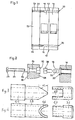
- a molded case circuit breaker designated by the general reference 10, in particular a miniature bipolar circuit breaker is formed by the association of two poles 12, 14 joined to one another and joined by rivets 16, the heads 18 are housed in a recess 20.
- the circuit breaker may include a greater number of poles or, if appropriate, a single pole, the rivets 16 joining the two constituent parts of the molded housing.
- the rivets 16 are of the tubular type and are generally four in number distributed or arranged in the vicinity of the four corners of the molded housing.
- An auxiliary block 22 containing for example a current-emitting coil or an auxiliary contact, is attached to the molded case of the pole 12 and secured to the latter by one or more screws 24 passing through transverse orifices 26 formed in the case of the block 22
- This case is advantageously made of molded material and its profile corresponds to that of the case of the circuit breaker 10.
- the assembly can be of the type with snap-fastening on a DIN rail (not re present). With particular reference to FIG. 2, it can be seen that the orifice 26 opens onto the face 28 attached to the pole 12 in a recess 30 of square section. The opposite end of the orifice 26 opens into a recess 32 for housing the head 34 of the screw 24.
- the orifice 26 is open on its edge to form a groove or slot into which the screw 24, fitted, can be introduced. of its nut 36 by lateral sliding.
- the nut 36 shown in detail in Figures 3 and 4, is constituted by a cylindrical sleeve with an outside diameter slightly smaller than the internal diameter of the rivet 16, and having a notch 40 on one of its ends.
- the notch 40 in the form of a saw cut is of a width close to that of the internal bore of the nut 36, so as to leave only two tabs 42 constituting the edges of the notch 40.
- the assembly device further comprises a socket 38 threaded on the screw 24 between the head 34 and the nut 36.
- the diameter of the internal bore of the socket 38 is greater than that of the screw 24 to allow free sliding of the socket 38 on the screw 24.
- the socket 38 has on one of its ends a square head 44 of cross section conjugate with that of the recess 30.
- the end opposite to the head 44 of the socket 38 is cut in wedge shape 46, for example at an angle close to 60 °, the bushing being arranged on the screw 24 so that the wedge end 46 is capable of being inserted into the notch 40 between the tongues 42 of nut 36.
Landscapes
- Engineering & Computer Science (AREA)
- General Engineering & Computer Science (AREA)
- Mechanical Engineering (AREA)
- Architecture (AREA)
- Civil Engineering (AREA)
- Structural Engineering (AREA)
- Breakers (AREA)
- Dowels (AREA)
Applications Claiming Priority (2)
| Application Number | Priority Date | Filing Date | Title |
|---|---|---|---|
| FR7916672 | 1979-06-26 | ||
| FR7916672A FR2459897A1 (fr) | 1979-06-26 | 1979-06-26 | Dispositif d'assemblage a ecrou expansible |
Publications (2)
| Publication Number | Publication Date |
|---|---|
| EP0022011A1 true EP0022011A1 (de) | 1981-01-07 |
| EP0022011B1 EP0022011B1 (de) | 1985-06-19 |
Family
ID=9227217
Family Applications (1)
| Application Number | Title | Priority Date | Filing Date |
|---|---|---|---|
| EP19800400929 Expired EP0022011B1 (de) | 1979-06-26 | 1980-06-23 | Montagevorrichtung mit ausdehnbarer Mutter |
Country Status (3)
| Country | Link |
|---|---|
| EP (1) | EP0022011B1 (de) |
| DE (1) | DE3070772D1 (de) |
| FR (1) | FR2459897A1 (de) |
Cited By (1)
| Publication number | Priority date | Publication date | Assignee | Title |
|---|---|---|---|---|
| CN109488674A (zh) * | 2018-10-16 | 2019-03-19 | 深圳市奥谱特科技有限公司 | 一种快速连接装置用的螺钉把手 |
Citations (3)
| Publication number | Priority date | Publication date | Assignee | Title |
|---|---|---|---|---|
| FR958326A (de) * | 1950-03-07 | |||
| FR2300482A1 (fr) * | 1975-02-06 | 1976-09-03 | Bassani Spa | Bases modulaires pour appareil |
| FR2420049A1 (fr) * | 1978-03-13 | 1979-10-12 | Merlin Gerin | Assemblage par vis de fixation |
-
1979
- 1979-06-26 FR FR7916672A patent/FR2459897A1/fr active Granted
-
1980
- 1980-06-23 EP EP19800400929 patent/EP0022011B1/de not_active Expired
- 1980-06-23 DE DE8080400929T patent/DE3070772D1/de not_active Expired
Patent Citations (3)
| Publication number | Priority date | Publication date | Assignee | Title |
|---|---|---|---|---|
| FR958326A (de) * | 1950-03-07 | |||
| FR2300482A1 (fr) * | 1975-02-06 | 1976-09-03 | Bassani Spa | Bases modulaires pour appareil |
| FR2420049A1 (fr) * | 1978-03-13 | 1979-10-12 | Merlin Gerin | Assemblage par vis de fixation |
Cited By (1)
| Publication number | Priority date | Publication date | Assignee | Title |
|---|---|---|---|---|
| CN109488674A (zh) * | 2018-10-16 | 2019-03-19 | 深圳市奥谱特科技有限公司 | 一种快速连接装置用的螺钉把手 |
Also Published As
| Publication number | Publication date |
|---|---|
| EP0022011B1 (de) | 1985-06-19 |
| FR2459897A1 (fr) | 1981-01-16 |
| DE3070772D1 (de) | 1985-07-25 |
| FR2459897B1 (de) | 1983-07-29 |
Similar Documents
| Publication | Publication Date | Title |
|---|---|---|
| FR2534441A1 (fr) | Support separateur pour la reunion temporaire de chassis et de panneaux a circuit | |
| EP1714161B1 (de) | Hilfselement zum fixieren eines stromsensors an einem elektrischen leiter | |
| FR2703193A1 (fr) | Appareil électrique, en particulier bloc de jonction, à borne de connexion mettant en Óoeuvre un écrou à serrage rapide. | |
| EP3323170B1 (de) | Frei verschiebbare elektrische verbindungsvorrichtung mit schutz gegen schäden durch fremdkörper | |
| EP0555157B1 (de) | Anschlussvorrichtung für einen Niederspannungsschalter mit Kunststoffgehäuse | |
| EP1181698A1 (de) | Stromsensor mit zwei montagepositionen | |
| FR2615666A1 (fr) | Plaque porte-balais perfectionnee notamment pour moteur electrique | |
| EP0022011A1 (de) | Montagevorrichtung mit ausdehnbarer Mutter | |
| WO1998026325A1 (fr) | Dispositif a charniere | |
| EP0626533B1 (de) | Halteschelle auf einer Stütze für ein Rohr oder dergleichen | |
| FR2727260A1 (fr) | Support pour appareillage electrique | |
| EP1531525A1 (de) | Kabelklemme mit vergrösserter Klemmfläche und damit ausgerüsteter Verbinderblock | |
| CA2011795C (fr) | Terminal femelle de distribution de courant electrique dote de moyens anti-electrocution | |
| FR3073910A3 (fr) | Ensemble de fixation vis-ecrou muni d'un dispositif de verrouillage dudit ecrou et assemblage d'au moins deux plaques au moyen dudit ensemble | |
| FR2614132A1 (fr) | Dispositif d'assemblage de boitiers moules miniature par des pions plastiques | |
| EP2123919B1 (de) | Starre Verbindung von Rohrteilen | |
| FR2463514A1 (fr) | Connecteur de batterie | |
| FR2784241A1 (fr) | Clip de contact, en particulier pour systemes de barre de bus | |
| EP0837528B1 (de) | Anschlussleiste | |
| EP1071184B1 (de) | Befestigungsklemmbacken für elektrische Geräte mit zwei unterschiedlichen Wirkungszonen | |
| FR2734422A1 (fr) | Support d'appareil electrique pour goulotte a rails | |
| FR2711196A1 (fr) | Ecrou encagé à montage sur un rail ou analogue et assemblage obtenu à l'aide de cet écrou. | |
| FR2677084A1 (fr) | Dispositif d'assemblage pour profiles creux. | |
| FR2632458A1 (fr) | Connecteur electrique | |
| FR2582447A1 (fr) | Dispositif de connexion pour batterie d'accumulateur electrique |
Legal Events
| Date | Code | Title | Description |
|---|---|---|---|
| PUAI | Public reference made under article 153(3) epc to a published international application that has entered the european phase |
Free format text: ORIGINAL CODE: 0009012 |
|
| AK | Designated contracting states |
Designated state(s): BE CH DE GB IT NL SE |
|
| 17P | Request for examination filed |
Effective date: 19810518 |
|
| ITF | It: translation for a ep patent filed | ||
| GRAA | (expected) grant |
Free format text: ORIGINAL CODE: 0009210 |
|
| AK | Designated contracting states |
Designated state(s): BE CH DE GB IT LI NL SE |
|
| REF | Corresponds to: |
Ref document number: 3070772 Country of ref document: DE Date of ref document: 19850725 |
|
| PLBE | No opposition filed within time limit |
Free format text: ORIGINAL CODE: 0009261 |
|
| STAA | Information on the status of an ep patent application or granted ep patent |
Free format text: STATUS: NO OPPOSITION FILED WITHIN TIME LIMIT |
|
| 26N | No opposition filed | ||
| PGFP | Annual fee paid to national office [announced via postgrant information from national office to epo] |
Ref country code: NL Payment date: 19870630 Year of fee payment: 8 |
|
| PG25 | Lapsed in a contracting state [announced via postgrant information from national office to epo] |
Ref country code: LI Effective date: 19880630 Ref country code: CH Effective date: 19880630 |
|
| REG | Reference to a national code |
Ref country code: CH Ref legal event code: PL |
|
| PG25 | Lapsed in a contracting state [announced via postgrant information from national office to epo] |
Ref country code: SE Effective date: 19890624 |
|
| ITTA | It: last paid annual fee | ||
| PGFP | Annual fee paid to national office [announced via postgrant information from national office to epo] |
Ref country code: GB Payment date: 19890630 Year of fee payment: 10 |
|
| PGFP | Annual fee paid to national office [announced via postgrant information from national office to epo] |
Ref country code: BE Payment date: 19890725 Year of fee payment: 10 |
|
| PGFP | Annual fee paid to national office [announced via postgrant information from national office to epo] |
Ref country code: DE Payment date: 19890831 Year of fee payment: 10 |
|
| PG25 | Lapsed in a contracting state [announced via postgrant information from national office to epo] |
Ref country code: NL Effective date: 19900101 |
|
| NLV4 | Nl: lapsed or anulled due to non-payment of the annual fee | ||
| PG25 | Lapsed in a contracting state [announced via postgrant information from national office to epo] |
Ref country code: GB Effective date: 19900623 |
|
| PG25 | Lapsed in a contracting state [announced via postgrant information from national office to epo] |
Ref country code: BE Effective date: 19900630 |
|
| BERE | Be: lapsed |
Owner name: MERLIN GERIN Effective date: 19900630 |
|
| GBPC | Gb: european patent ceased through non-payment of renewal fee | ||
| PG25 | Lapsed in a contracting state [announced via postgrant information from national office to epo] |
Ref country code: DE Effective date: 19910403 |
|
| EUG | Se: european patent has lapsed |
Ref document number: 80400929.8 Effective date: 19900412 |