EP0022011A1 - Dispositif d'assemblage à écrou expansible - Google Patents
Dispositif d'assemblage à écrou expansible Download PDFInfo
- Publication number
- EP0022011A1 EP0022011A1 EP19800400929 EP80400929A EP0022011A1 EP 0022011 A1 EP0022011 A1 EP 0022011A1 EP 19800400929 EP19800400929 EP 19800400929 EP 80400929 A EP80400929 A EP 80400929A EP 0022011 A1 EP0022011 A1 EP 0022011A1
- Authority
- EP
- European Patent Office
- Prior art keywords
- nut
- assembly device
- screw
- notched
- head
- Prior art date
- Legal status (The legal status is an assumption and is not a legal conclusion. Google has not performed a legal analysis and makes no representation as to the accuracy of the status listed.)
- Granted
Links
Images
Classifications
-
- F—MECHANICAL ENGINEERING; LIGHTING; HEATING; WEAPONS; BLASTING
- F16—ENGINEERING ELEMENTS AND UNITS; GENERAL MEASURES FOR PRODUCING AND MAINTAINING EFFECTIVE FUNCTIONING OF MACHINES OR INSTALLATIONS; THERMAL INSULATION IN GENERAL
- F16B—DEVICES FOR FASTENING OR SECURING CONSTRUCTIONAL ELEMENTS OR MACHINE PARTS TOGETHER, e.g. NAILS, BOLTS, CIRCLIPS, CLAMPS, CLIPS OR WEDGES; JOINTS OR JOINTING
- F16B13/00—Dowels or other devices fastened in walls or the like by inserting them in holes made therein for that purpose
- F16B13/04—Dowels or other devices fastened in walls or the like by inserting them in holes made therein for that purpose with parts gripping in the hole or behind the reverse side of the wall after inserting from the front
- F16B13/08—Dowels or other devices fastened in walls or the like by inserting them in holes made therein for that purpose with parts gripping in the hole or behind the reverse side of the wall after inserting from the front with separate or non-separate gripping parts moved into their final position in relation to the body of the device without further manual operation
- F16B13/0858—Dowels or other devices fastened in walls or the like by inserting them in holes made therein for that purpose with parts gripping in the hole or behind the reverse side of the wall after inserting from the front with separate or non-separate gripping parts moved into their final position in relation to the body of the device without further manual operation with an expansible sleeve or dowel body driven against a tapered or spherical expander plug
-
- F—MECHANICAL ENGINEERING; LIGHTING; HEATING; WEAPONS; BLASTING
- F16—ENGINEERING ELEMENTS AND UNITS; GENERAL MEASURES FOR PRODUCING AND MAINTAINING EFFECTIVE FUNCTIONING OF MACHINES OR INSTALLATIONS; THERMAL INSULATION IN GENERAL
- F16B—DEVICES FOR FASTENING OR SECURING CONSTRUCTIONAL ELEMENTS OR MACHINE PARTS TOGETHER, e.g. NAILS, BOLTS, CIRCLIPS, CLAMPS, CLIPS OR WEDGES; JOINTS OR JOINTING
- F16B5/00—Joining sheets or plates, e.g. panels, to one another or to strips or bars parallel to them
- F16B5/02—Joining sheets or plates, e.g. panels, to one another or to strips or bars parallel to them by means of fastening members using screw-thread
-
- H—ELECTRICITY
- H02—GENERATION; CONVERSION OR DISTRIBUTION OF ELECTRIC POWER
- H02G—INSTALLATION OF ELECTRIC CABLES OR LINES, OR OF COMBINED OPTICAL AND ELECTRIC CABLES OR LINES
- H02G3/00—Installations of electric cables or lines or protective tubing therefor in or on buildings, equivalent structures or vehicles
- H02G3/02—Details
- H02G3/08—Distribution boxes; Connection or junction boxes
- H02G3/086—Assembled boxes
Definitions
- the invention relates to a removable rigid assembly device of an auxiliary unit to a molded case with elements assembled by tubular rivets, in particular to a molded case of a miniature circuit breaker comprising a clamping screw for metals with cylindrical body and with a head bearing on said auxiliary block and an expandable assembly capable of being inserted into the end of the tubular rivet and of receiving the screwed cylindrical part of said screw.
- the Applicant has already proposed in French patent application No. 2,420,049 an assembly device of the kind mentioned, allowing assembly or disassembly by the customer or the distributor of elements of a modular system of miniature electrical equipment.
- the main advantage consists in not requiring any modification of the basic device, in this case the miniature circuit breaker.
- the proposed system is satisfactory if the manufacturing precision, in particular of the circuit-breaker assembly rivets and the fixing screws is sufficient, but this precision imposes certain manufacturing constraints, which it is advantageous to overcome.
- the screwing of the assembly screw does not exert a clamping force between the assembled elements and a certain play may remain.
- the object of the present invention is to provide an assembly device which does not have these drawbacks and it is characterized in that said expandable assembly comprises a nut with cylindrical internal bore threaded and with a radially deformable notched end and a non-tapped, interposed sleeve. between the nut and the head and having a wedge-shaped end capable of cooperating with said notched end to block said nut by radial expansion of the notched end in the rivet, and an opposite end having a rotating immobilization head likely to fit into a housing of conjugate form.
- a known assembly device makes use of an expandable nut engaged with gentle friction in a cylindrical bore.
- the assembly rivets of the circuit breaker boxes have insufficient manufacturing precision to ensure with certainty the immobilization in rotation of the nut during screwing.
- some rivets rotate in their housing, making any screwing impossible. This known device is not applicable to the present invention.
- the constituent elements of the assembly - in particular the screw, the nut and the sleeve, are parts of current manufacture, the nut being for example a tubular part with internal thread whose end is notched by a saw cut .
- the socket and the nut are advantageously made of bronze, so as to have sufficient elasticity to the elastic deformation of the edges of the notch which becomes embedded in the internal wall of the rivets.
- the assembly elements in this case the screw, the socket and the nut, are delivered assembled and the holes for the passage of the screw formed in the auxiliary block are arranged in slots allowing lateral insertion of the screw without removing the nut and the socket.
- a molded case circuit breaker designated by the general reference 10, in particular a miniature bipolar circuit breaker is formed by the association of two poles 12, 14 joined to one another and joined by rivets 16, the heads 18 are housed in a recess 20.
- the circuit breaker may include a greater number of poles or, if appropriate, a single pole, the rivets 16 joining the two constituent parts of the molded housing.
- the rivets 16 are of the tubular type and are generally four in number distributed or arranged in the vicinity of the four corners of the molded housing.
- An auxiliary block 22 containing for example a current-emitting coil or an auxiliary contact, is attached to the molded case of the pole 12 and secured to the latter by one or more screws 24 passing through transverse orifices 26 formed in the case of the block 22
- This case is advantageously made of molded material and its profile corresponds to that of the case of the circuit breaker 10.
- the assembly can be of the type with snap-fastening on a DIN rail (not re present). With particular reference to FIG. 2, it can be seen that the orifice 26 opens onto the face 28 attached to the pole 12 in a recess 30 of square section. The opposite end of the orifice 26 opens into a recess 32 for housing the head 34 of the screw 24.
- the orifice 26 is open on its edge to form a groove or slot into which the screw 24, fitted, can be introduced. of its nut 36 by lateral sliding.
- the nut 36 shown in detail in Figures 3 and 4, is constituted by a cylindrical sleeve with an outside diameter slightly smaller than the internal diameter of the rivet 16, and having a notch 40 on one of its ends.
- the notch 40 in the form of a saw cut is of a width close to that of the internal bore of the nut 36, so as to leave only two tabs 42 constituting the edges of the notch 40.
- the assembly device further comprises a socket 38 threaded on the screw 24 between the head 34 and the nut 36.
- the diameter of the internal bore of the socket 38 is greater than that of the screw 24 to allow free sliding of the socket 38 on the screw 24.
- the socket 38 has on one of its ends a square head 44 of cross section conjugate with that of the recess 30.
- the end opposite to the head 44 of the socket 38 is cut in wedge shape 46, for example at an angle close to 60 °, the bushing being arranged on the screw 24 so that the wedge end 46 is capable of being inserted into the notch 40 between the tongues 42 of nut 36.
Landscapes
- Engineering & Computer Science (AREA)
- General Engineering & Computer Science (AREA)
- Mechanical Engineering (AREA)
- Architecture (AREA)
- Civil Engineering (AREA)
- Structural Engineering (AREA)
- Breakers (AREA)
- Dowels (AREA)
Abstract
Description
- L'invention est relative à un dispositif d'assemblage rigide démontable d'un bloc auxiliaire à un boîtier moulé à éléments assemblés par des rivets tubulaires, notamment à un bottier moulé d'un disjoncteur miniature comprenant une vis de serrage pour métaux à corps cylindrique et à tête prenant appui sur ledit bloc auxiliaire et un ensemble expansible susceptible de s'insérer dans l'extrémité du rivet tubulaire et de recevoir à vissage la partie cylindrique filetée de ladite vis.
- La demanderesse a déjà proposé dans la demande de brevet français N° 2.420.049 un dispositif d'assemblage du genre mentionné, permettant un assemblage ou un démontage par le client oule distributeur d'éléments d'un système modulaire d'appareillage électrique miniature. L'avantage principal consiste dans le fait de ne nécessiter aucune modification de l'appareil de base, en l'occurrence du disjoncteur miniature. Le système proposé donne satisfaction si la précision de fabrication, notamment des rivets d'assemblage du disjoncteur et des vis de fixation est suffisante, mais cette précision impose certaines contraintes de fabrication, dont il est avantageux de s'affranchir. De plus, le vissage de la vis d'assemblage n'exerce pas un effort de serrage entre les éléments assemblés et un certain jeu peut subsister.
- La présente invention a pour but de réaliser un dispositif d'assemblage ne présentant pas ces inconvénients et elle est caractérisée par le fait que ledit ensemble expansible comporte un écrou à alésage interne cylindrique fileté et à extrémité entaillée déformable radialement et une douille non taraudée, intercalée entre l'écrou et la tête et ayant une extrémité en forme de coin susceptible de coopérer avec ladite extrémité entaillée pour bloquer ledit écrou par expansion radiale de l'extrémité entaillée dans le rivet, et une extrémité opposée présentant une tête d'immobilisation en rotation susceptible de s'insérer dans un logement de forme conjuguée.
- L'enfoncement du coin dans l'entaille, lors du serrage de la vis, provoque l'écartement des bords de l'entaille, qui s'incrustent dans la paroi interne du rivet pour solidariser l'écrou et le rivet. Un vissage poursuivi rapproche la tête solidaire du bloc auxiliaire, de l'écrou solidajre du boîtier du disjoncteur. Toute rotation de l'ensemble douille écrou est empêchée par la tête polygonale de la douille logée dans un évidement de section conjuguée du bloc auxiliaire.
- Un dispositif d'assemblage connu (brevet français N° 958.326) fait usage d'un écrou expansible engagé à frottement doux dans un alésage cylindrique. Les rivets d'assemblage des boîtiers de disjoncteur ont une précision de fabrication insuffisante pour assurer avec certitude l'immobilisation en rotation de l'écrou lors du vissage. De plus, certains rivets tournent dans leur logement, rendant impossible tout vissage. Ce dispositif connu n'est pas applicable à la présente invention.
- Les éléments constitutifs de l'assemblage,- notamment la vis, l'écrou et la douille, sont des pièces de fabrication courante, l'écrou étant par exemple une pièce tubulaire à filetage interne dont l'extrémité est entaillée par un trait de scie. La douille et l'écrou sont avantageusement en bronze, de manière à présenter une élasticité suffisante à la déformation élastique des bords de l'entaille venant s'incruster dans la paroi interne des rivets.
- Selon un développement de l'invention, permettant d'éviter toute erreur de montage, les éléments d'assemblage, en l'occurrence la vis, la douille et l'écrou, sont livrés assemblés et les orifices de passage de la vis ménagés dans le bloc auxiliaire sont agencés en fentes permettant l'insertion latéralement de la vis sans enlèvement de l'écrou et de la douille.
- D'autres avantages et caractéristiques de l'invention ressortiront plus clairement de la description, qui va suivre d'un mode de mise en oeuvre de l'invention, donné à titre d'exemple non limitatif et représenté au dessin annexé, dans lequel :
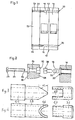
- la figure 1 est une vue schématique en plan d'un disjoncteur à boîtier moulé auquel est assemblé un bloc auxiliaire par un dispositif d'assemblage, selon l'invention;
- la figure 2 est une vue éclatée, à échelle agrandie et en coupe du dispositif d'assemblage selon la fig. 1;
- la figure 3 est une vue à échelle agrandie de la douille et de l'écrou, représentée à la figure 2;
- la figure 4 est une vue en plan de la douille et de l'écrou de la figure 3.
- Sur les figures, un disjoncteur à boîtier moulé, désigné par le repère général 10, notamment un disjoncteur miniature bipolaire est constitué par l'association de deux pôles 12, 14 accolés l'un à l'autre et réunis par des rivets 16 dont les têtes 18 sont logées dans un évidement 20.
- Il est clair que le disjoncteur peut comporter un nombre supérieur de pôles ou le cas échéant un seul pôle, les rivets 16 réunissant les deux parties constitutives du boîtier moulé. Les rivets 16 sont du type tubulaire et sont généralement au nombre de quatre répartis ou disposés au voisinage des quatre angles du boîtier moulé.
- Un bloc auxiliaire 22, contenant par exemple une bobine à émission de courant ou un contact auxiliaire, est accolé au boîtier moulé du pôle 12 et solidarisé à ce dernier par une ou plusieurs vis 24 traversant des orifices transversaux 26 ménagés dans le boîtier du bloc 22. Ce boitier est avantageusement en matière moulée et son profil correspond à celui du boîtier du disjoncteur 10. L'ensemble peut être du type à fixation par encliquetage sur un rail DIN (non représenté). En se référant plus particulièrement à la fig. 2, on voit que l'orifice 26 débouche sur la face 28 accolée au pôle 12 dans un évidement 30 de section carrée. L'extrémité opposée de l'orifice 26 débouche dans un évidement 32 de logement de la tête 34 de la vis 24. L'orifice 26 est ouvert sur sa tranche pour constituer une rainure ou fente dans laquelle peut être introduite la vis 24, équipée de son écrou 36 par glissement latéral. L'écrou 36, représenté en détail sur les figures 3 et 4, est constitué par un manchon cylindrique de diamètre extérieur léqèrement inférieur au diamètre interne du rivet 16, et présentant une entaille 40 sur l'une de ses extrémités. L'entaille 40 en forme de trait de scie est d'une largeur voisine de celle de l'alésage interne de l'écrou 36, de manière à ne laisser subsister que deux languettes 42 constituant les bords de l'entaille 40.
- Le dispositif d'assemblage comporte en outre une douille 38 enfilée sur la vis 24 entre la tête 34 et l'écrou 36. Le diamètre de l'alésage interne de la douille 38 est supérieur à celui de la vis 24 pour autoriser un coulissement libre de la douille 38 sur la vis 24. La douille 38 comporte sur l'une de ses extrémités une tête carrée 44 de section conjuguée à celle de l'évidement 30. L'extrémité opposée à la tête 44 de la douille 38 est taillée en forme de coin 46, par exemple d'un angle voisin de 60°, la douille étant disposée sur la vis 24 de telle manière que l'extrémité en coin 46 est susceptible de s'insérer dans l'entaille 40 entre les languettes 42 de l'écrou 36.
- Le dispositif d'assemblage selon l'invention est mis en oeuvre de la manière suivante :
- La ou les vis 24, équipées de douilles 38 et des écrous expansibles 36, sont livrées avec le bloc auxiliaire 22. Pour le montage il suffit de glisser les vis 24 dans les rainures ou orifices 26, la douille et l'écrou 36 étant disposés du côté de la face 28. En accolant le bloc 22 contre le disjoncteur 10, l'écrou 36 et la partie adjacente de la douille 38 pénètrent dans l'extrémité du rivet 16, tandis que la tête 44 de la douille 38 pénètre dans l'évidement 30. La douille 38 et l'écrou 36 sont immobilisés en rotation par la section polygonale de l'évidement 30 et de la tête 44 et par l'emboitement du coin 46 dans l'entaille 40, et lors du vissage de la vis 24 cette dernière se visse dans l'écrou 36. Lors du serrage le coin 46 pénètre dans l'entaille 40 en écartant les languettes 42 dont les bords s'incrustent dans la paroi interne du rivet 16 solidarisant l'écrou 36 au rivet 16. La force d'incrustation dépend du degré de serrage de la vis 24 qui pousse le bloc auxiliaire 22 contre le disjoncteur 10. Le démontage du bloc auxiliaire 22 s'effectue par simple dévissage des vis 24, l'élasticité des languettes 42 provoquant le rétrécissement de l'écrou 36 et la libération du bloc 22.
- L'invention n'est bien entendu nullement limitée au mode de mise en oeuvre plus particulièrement décrit.
Claims (7)
Applications Claiming Priority (2)
| Application Number | Priority Date | Filing Date | Title |
|---|---|---|---|
| FR7916672A FR2459897A1 (fr) | 1979-06-26 | 1979-06-26 | Dispositif d'assemblage a ecrou expansible |
| FR7916672 | 1979-06-26 |
Publications (2)
| Publication Number | Publication Date |
|---|---|
| EP0022011A1 true EP0022011A1 (fr) | 1981-01-07 |
| EP0022011B1 EP0022011B1 (fr) | 1985-06-19 |
Family
ID=9227217
Family Applications (1)
| Application Number | Title | Priority Date | Filing Date |
|---|---|---|---|
| EP19800400929 Expired EP0022011B1 (fr) | 1979-06-26 | 1980-06-23 | Dispositif d'assemblage à écrou expansible |
Country Status (3)
| Country | Link |
|---|---|
| EP (1) | EP0022011B1 (fr) |
| DE (1) | DE3070772D1 (fr) |
| FR (1) | FR2459897A1 (fr) |
Cited By (1)
| Publication number | Priority date | Publication date | Assignee | Title |
|---|---|---|---|---|
| CN109488674A (zh) * | 2018-10-16 | 2019-03-19 | 深圳市奥谱特科技有限公司 | 一种快速连接装置用的螺钉把手 |
Citations (3)
| Publication number | Priority date | Publication date | Assignee | Title |
|---|---|---|---|---|
| FR958326A (fr) * | 1950-03-07 | |||
| FR2300482A1 (fr) * | 1975-02-06 | 1976-09-03 | Bassani Spa | Bases modulaires pour appareil |
| FR2420049A1 (fr) * | 1978-03-13 | 1979-10-12 | Merlin Gerin | Assemblage par vis de fixation |
-
1979
- 1979-06-26 FR FR7916672A patent/FR2459897A1/fr active Granted
-
1980
- 1980-06-23 EP EP19800400929 patent/EP0022011B1/fr not_active Expired
- 1980-06-23 DE DE8080400929T patent/DE3070772D1/de not_active Expired
Patent Citations (3)
| Publication number | Priority date | Publication date | Assignee | Title |
|---|---|---|---|---|
| FR958326A (fr) * | 1950-03-07 | |||
| FR2300482A1 (fr) * | 1975-02-06 | 1976-09-03 | Bassani Spa | Bases modulaires pour appareil |
| FR2420049A1 (fr) * | 1978-03-13 | 1979-10-12 | Merlin Gerin | Assemblage par vis de fixation |
Cited By (1)
| Publication number | Priority date | Publication date | Assignee | Title |
|---|---|---|---|---|
| CN109488674A (zh) * | 2018-10-16 | 2019-03-19 | 深圳市奥谱特科技有限公司 | 一种快速连接装置用的螺钉把手 |
Also Published As
| Publication number | Publication date |
|---|---|
| EP0022011B1 (fr) | 1985-06-19 |
| DE3070772D1 (de) | 1985-07-25 |
| FR2459897A1 (fr) | 1981-01-16 |
| FR2459897B1 (fr) | 1983-07-29 |
Similar Documents
| Publication | Publication Date | Title |
|---|---|---|
| FR2534441A1 (fr) | Support separateur pour la reunion temporaire de chassis et de panneaux a circuit | |
| EP1714161B1 (fr) | Element auxiliaire pour fixer un capteur de courant a un conducteur electrique | |
| FR2703193A1 (fr) | Appareil électrique, en particulier bloc de jonction, à borne de connexion mettant en Óoeuvre un écrou à serrage rapide. | |
| EP0555157B1 (fr) | Dispositif de raccordement d'un disjonteur basse tension à boîtier moulé | |
| WO2000072339A1 (fr) | Capteur de courant a deux positions de montage | |
| FR2615666A1 (fr) | Plaque porte-balais perfectionnee notamment pour moteur electrique | |
| EP0022011A1 (fr) | Dispositif d'assemblage à écrou expansible | |
| FR2537775A1 (fr) | Support de fusible de securite avec dispositif de selection de tension | |
| WO1998026325A1 (fr) | Dispositif a charniere | |
| EP0626533B1 (fr) | Collier de maintien, sur un support, d'un tube ou analogue | |
| FR2727260A1 (fr) | Support pour appareillage electrique | |
| EP1531525A1 (fr) | Serre-câble à plage de serrage èlargie et bloc de jonction muni d'un tel serre-câble | |
| CA2011795C (fr) | Terminal femelle de distribution de courant electrique dote de moyens anti-electrocution | |
| FR3073910A3 (fr) | Ensemble de fixation vis-ecrou muni d'un dispositif de verrouillage dudit ecrou et assemblage d'au moins deux plaques au moyen dudit ensemble | |
| FR2614132A1 (fr) | Dispositif d'assemblage de boitiers moules miniature par des pions plastiques | |
| EP2123919B1 (fr) | Assemblage rigide de pièces tubulaires | |
| FR2463514A1 (fr) | Connecteur de batterie | |
| FR2860346A1 (fr) | Appareil electrique comportant un boitier isolant et une borne a connexion automatique disposee dans ledit boitier | |
| FR2784241A1 (fr) | Clip de contact, en particulier pour systemes de barre de bus | |
| FR2709601A1 (fr) | Cosse pour batterie. | |
| EP0837528B1 (fr) | Répartiteur | |
| EP1071184B1 (fr) | Griffe d'ancrage à deux zones géographiques d'action distinctes pour mécanisme électrique | |
| FR2734422A1 (fr) | Support d'appareil electrique pour goulotte a rails | |
| FR2711196A1 (fr) | Ecrou encagé à montage sur un rail ou analogue et assemblage obtenu à l'aide de cet écrou. | |
| FR2677084A1 (fr) | Dispositif d'assemblage pour profiles creux. |
Legal Events
| Date | Code | Title | Description |
|---|---|---|---|
| PUAI | Public reference made under article 153(3) epc to a published international application that has entered the european phase |
Free format text: ORIGINAL CODE: 0009012 |
|
| AK | Designated contracting states |
Designated state(s): BE CH DE GB IT NL SE |
|
| 17P | Request for examination filed |
Effective date: 19810518 |
|
| ITF | It: translation for a ep patent filed | ||
| GRAA | (expected) grant |
Free format text: ORIGINAL CODE: 0009210 |
|
| AK | Designated contracting states |
Designated state(s): BE CH DE GB IT LI NL SE |
|
| REF | Corresponds to: |
Ref document number: 3070772 Country of ref document: DE Date of ref document: 19850725 |
|
| PLBE | No opposition filed within time limit |
Free format text: ORIGINAL CODE: 0009261 |
|
| STAA | Information on the status of an ep patent application or granted ep patent |
Free format text: STATUS: NO OPPOSITION FILED WITHIN TIME LIMIT |
|
| 26N | No opposition filed | ||
| PGFP | Annual fee paid to national office [announced via postgrant information from national office to epo] |
Ref country code: NL Payment date: 19870630 Year of fee payment: 8 |
|
| PG25 | Lapsed in a contracting state [announced via postgrant information from national office to epo] |
Ref country code: LI Effective date: 19880630 Ref country code: CH Effective date: 19880630 |
|
| REG | Reference to a national code |
Ref country code: CH Ref legal event code: PL |
|
| PG25 | Lapsed in a contracting state [announced via postgrant information from national office to epo] |
Ref country code: SE Effective date: 19890624 |
|
| ITTA | It: last paid annual fee | ||
| PGFP | Annual fee paid to national office [announced via postgrant information from national office to epo] |
Ref country code: GB Payment date: 19890630 Year of fee payment: 10 |
|
| PGFP | Annual fee paid to national office [announced via postgrant information from national office to epo] |
Ref country code: BE Payment date: 19890725 Year of fee payment: 10 |
|
| PGFP | Annual fee paid to national office [announced via postgrant information from national office to epo] |
Ref country code: DE Payment date: 19890831 Year of fee payment: 10 |
|
| PG25 | Lapsed in a contracting state [announced via postgrant information from national office to epo] |
Ref country code: NL Effective date: 19900101 |
|
| NLV4 | Nl: lapsed or anulled due to non-payment of the annual fee | ||
| PG25 | Lapsed in a contracting state [announced via postgrant information from national office to epo] |
Ref country code: GB Effective date: 19900623 |
|
| PG25 | Lapsed in a contracting state [announced via postgrant information from national office to epo] |
Ref country code: BE Effective date: 19900630 |
|
| BERE | Be: lapsed |
Owner name: MERLIN GERIN Effective date: 19900630 |
|
| GBPC | Gb: european patent ceased through non-payment of renewal fee | ||
| PG25 | Lapsed in a contracting state [announced via postgrant information from national office to epo] |
Ref country code: DE Effective date: 19910403 |
|
| EUG | Se: european patent has lapsed |
Ref document number: 80400929.8 Effective date: 19900412 |